

Napoleon Ascent X 70, GX70NTE-1, GX70PTE-1 Installation And Operation Manual
NATURAL GAS MODELS:
GX70NTE-1
ADD PRODUCT CODE HERE (TRADE GOTHIC LT STD FONT)
ENGLISH
PROPANE GAS MODELS:
SAFETY INFORMATION
!
WARNING
FIRE OR EXPLOSION HAZARD
Failure to follow safety warnings exactly
could result in serious injury, death, or
property damage.
- Do not store or use gasoline or other
fl ammable vapors and liquids in the vicinity of
this or any other appliance.
- WHAT TO DO IF YOU SMELL GAS:
• Do not try to light any appliance.
• Do not touch any electrical switch; do not
use any phone in your building.
• Immediately call your gas supplier from a
neighbour’s phone. Follow the gas
supplier’s instructions.
• If you cannot reach your gas supplier, call
the fi re department.
GX70PTE-1
FRENCH
PG. 53
INSTALLATION AND
ADD MANUAL TITLE
OPERATION MANUAL
Product Name / Code
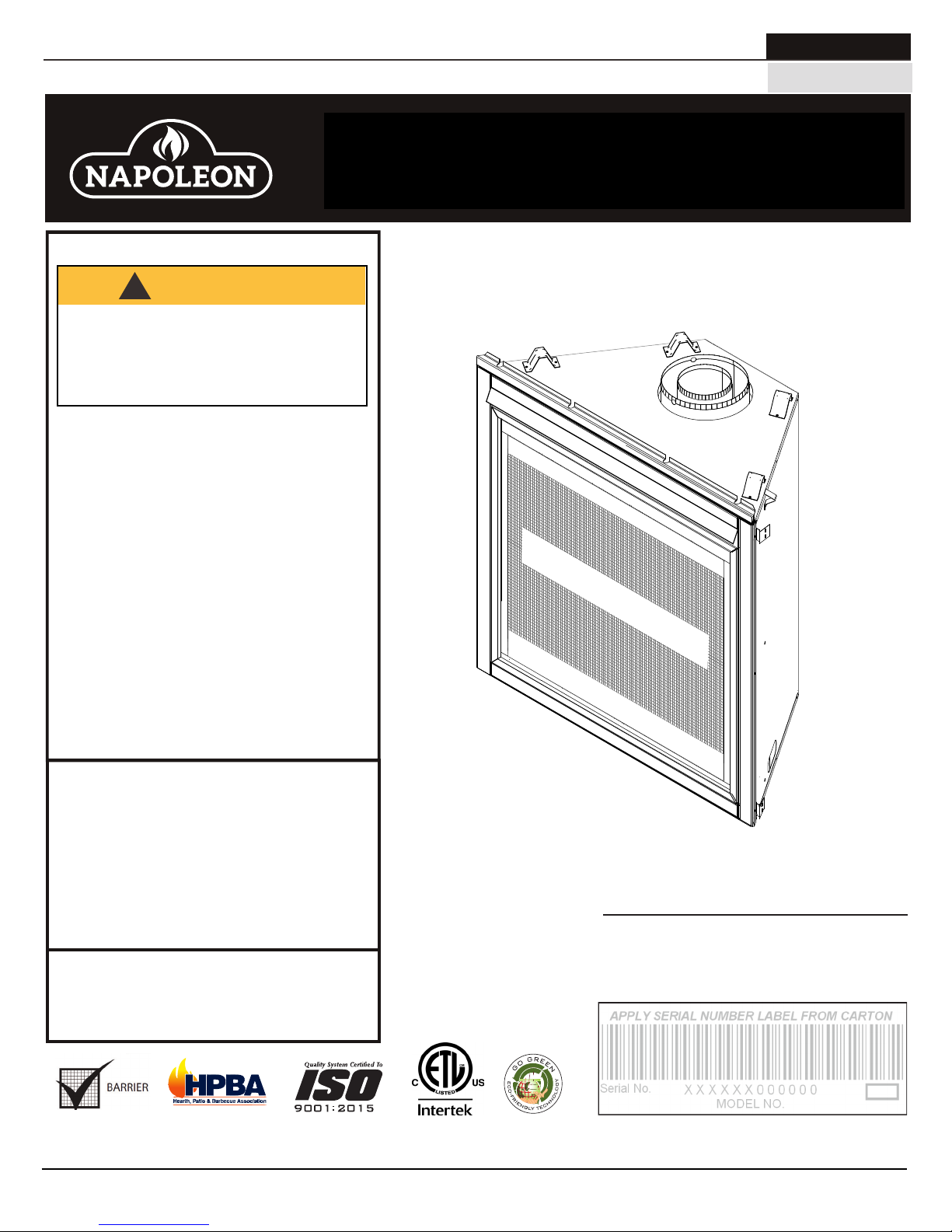
Ascent™ X 70
(GX70-1 illustrated)
(see price book)
ADD ____ ILLUSTRATED
SAFETY BARRIER
ADD PRODUCT IMAGE
- Installation and service must be
performed by a qualifi ed installer, service
agency, or the supplier.
This appliance may be installed in an aftermarket,
permanently located, manufactured home (USA
only) or mobile home, where not prohibited by
local codes.
This appliance is only for use with the type of gas
indicated on the rating plate. This appliance is
not convertible for use with other gases, unless
a certifi ed kit is used.
INSTALLER:
Leave this manual with the appliance
CONSUMER:
Retain this manual for future reference
Wolf Steel Ltd., 24 Napoleon Rd., Barrie, ON, L4M 0G8 Canada / 103 Miller Drive, Crittenden, Kentucky, USA, 41030
Phone 1 (866) 820-8686 • www.napoleonfi replaces.com • hearth@napoleonproducts.com
CSA 2.22 AND ANSI Z21.50 FOR VENTED DECORATIVE GAS APPLIANCES
CSA /
INTERTEK
LOGO
FOR INDOOR USE ONLY
CERTIFIED TO THE CANADIAN AND AMERICAN NATIONAL STANDARDS:
IF INSTALLATION + OPERATION, ADD SERIAL
NUMBER LABEL HERE
IF SEPARATE MANUALS, ADD “PLACE
BARCODE LABEL ON THE OWNER’S MANUAL”
$10.00
W415-1793 / A / 05.07.18
EN
DANGER
!
WARNING
safety information
• This appliance is hot when operated and
can cause severe burns if contacted.
• Any changes or alterations to this
appliance or its controls can be
dangerous and is prohibited.
• Do not operate appliance before reading and
understanding operating instructions. Failure
to operate appliance according to operating
instructions could cause fi re or injury.
• Ensure the glass door is opened or removed
when lighting the pilot for the fi rst time and
when the gas supply has run out.
• Risk of fi re or asphyxiation do not operate
appliance with fi xed glass removed and never
obstruct the front opening of the appliance.
• Objects placed in front of the appliance must
be kept a minimum of 4 feet (1.22m) from the
front face of the appliance.
• Do not connect 110 volts to the control valve,
with the exception of models; GSST8 and GT8.
• Risk of burns. The appliance should be turned off and cooled before servicing.
• Do not install damaged, incomplete or substitute components.
• Risk of cuts and abrasions. Wear protective gloves, protective footwear, and safety glasses during
installation. Sheet metal edges may be sharp.
• Do not burn wood or other materials in this appliance.
• Provide adequate ventilation and combustion air. Provide adequate accessibility clearance for servicing
and operating the appliance. Never obstruct the front opening of the appliance.
• The appliance area must be kept clear and free from combustible materials, gasoline and other
fl ammable vapors and liquids.
• High pressure will damage valve. Disconnect gas supply piping before pressure testing gas line at
test pressures above 1/2 psig. Close the manual shut-off valve before pressure testing gas line at test
pressures equal to or less than 1/2 psig (35mb).
• The appliance must not be operated at temperatures below freezing (32°F / 0°C). Allow the appliance
to warm to above freezing prior to operation, with the exception of models; GSS36, GSS42; these
appliances are suitable for 0°F / -18°C.
• Children and adults should be alerted to hazards of high surface temperature and should stay
away to avoid burns or clothing ignition.
• Young children should be carefully supervised when they are in the same room as the
appliance. Toddlers, young children and others may be susceptible to accidental contact
burns. A physical barrier is recommended if there are at risk individuals in the house. To
restrict access to an appliance or stove, install an adjustable safety gate to keep toddlers,
young children and other at risk individuals out of the room and away from hot surfaces.
• Clothing or other fl ammable material should not be placed on or near the appliance.
• Due to high temperatures, the appliance should be located out of traffi c and away from
furniture and draperies.
• Furniture or other objects must be kept a minimum of 4 feet (1.22m) away from the front of the appliance.
• Ensure you have incorporated adequate safety measure to protect infants/toddlers from touching hot
surfaces.
• Even after the appliance is off, it will remain hot for an extended period of time.
• Check with your local hearth specialty dealer for safety screens and hearth guards to protect children
from hot surfaces. These screens and guards must be fastened to the fl oor.
• Any safety screen, guard or barrier removed for servicing the appliance, must be replaced prior
to operating the appliance.
• It is imperative that the control compartments, burners and circulating blower and its passageway in the
appliance and venting system are kept clean. The appliance and its venting system should be inspected
before use and at least annually by a qualifi ed service person. More frequent cleaning may be required
due to excessive lint from carpeting, bedding material, etc. The appliance area must be kept clear and
free from combustible materials, gasoline and other fl ammable vapors and liquids.
• If the appliance shuts off, do not re-light until you provide fresh air. If appliance keeps shutting off, have it
serviced. Keep burner and control compartment clean.
• Under no circumstances should this appliance be modifi ed.
!
HOT GLASS WILL CAUSE
BURNS.
DO NOT TOUCH GLASS UNTIL
COOLED.
NEVER ALLOW CHILDREN TO
TOUCH GLASS.
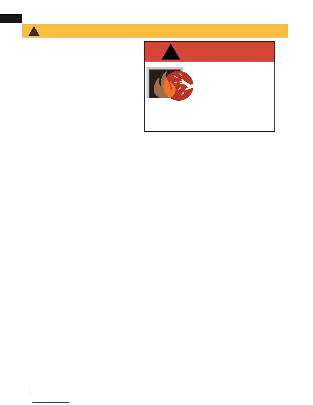
A barrier designed to reduce the risk of burns from the
hot viewing glass is provided with this appliance and
shall be installed for the protection of children and other
at-risk individuals.
2
W415-1793 / A / 05.07.18

• It is imperative that the control compartments, burners and circulating blower and its passageway in the
appliance and venting system are kept clean. The appliance and its venting system should be inspected
before use and at least annually by a qualifi ed service person. More frequent cleaning may be required
due to excessive lint from carpeting, bedding material, etc. The appliance area must be kept clear and
free from combustible materials, gasoline and other fl ammable vapors and liquids.
• If the appliance shuts off, do not re-light until you provide fresh air. If appliance keeps shutting off, have it
serviced. Keep burner and control compartment clean.
• Under no circumstances should this appliance be modifi ed.
HOT GLASS WILL CAUSE
BURNS.
DO NOT TOUCH GLASS UNTIL
COOLED.
NEVER ALLOW CHILDREN TO
TOUCH GLASS.
!
DANGER
A barrier designed to reduce the risk of burns from the
hot viewing glass is provided with this appliance and
shall be installed for the protection of children and other
at-risk individuals.
!
WARNING
!
WARNING
WARNING
• Do not allow wind or fans to blow directly into the appliance. Avoid any drafts that alter burner fl ame
patterns.
• Do not use a blower insert, heat exchanger insert or other accessory not approved for use with this
appliance.
• This appliance must not be connected to a chimney fl ue pipe serving a separate solid fuel burning
appliance.
• Do not use this appliance if any part has been under water. Immediately call a qualifi ed service technician
to inspect the appliance and to replace any part of the control system and any gas control which has
been under water.
• Do not operate the appliance with the glass door removed, cracked or broken. Replacement of the glass
should be done by a licensed or qualifi ed service person, if equipped.
• Do not strike or slam shut the appliance glass door, if equipped.
• Only doors / optional fronts certifi ed with the appliance are to be installed on the appliance.
• Keep the packaging material out of reach of children and dispose of the material in a safe manner. As
with all plastic bags, these are not toys and should be kept away from children and infants.
• Carbon or soot should not occur in a vent free appliance as it can distribute into the living area of your
home. If you notice any signs of carbon or soot, immediately turn off your appliance and arrange to have
it serviced by a qualifi ed technician before operating it again.
• If equipped, the screen must be in place (closed) when the appliance is in operation.
• When equipped with pressure relief doors, they must be kept closed while the appliance is operating
to prevent exhaust fumes containing carbon monoxide, from entering into the home. Temperatures of
the exhaust escaping through these openings can also cause the surrounding combustible materials to
overheat and catch fi re.
• Carbon monoxide poisoning may lead to death; early signs of carbon monoxide poisoning resemble
the fl u, with headache, dizziness and/or nausea. If you have these signs, the heater may not be working
properly. Get fresh air at once! Have heater serviced. Some people; pregnant women, persons with heart
or lung disease, anemia, those under the infl uence of alcohol, those at high altitudes are more affected by
carbon monoxide than others. Failure to keep the primary air opening(s) of the burner(s) clean may result
in sooting and property damage.
• As with any combustion appliance, we recommend having your appliance regularly inspected and
serviced as well as having a Carbon Monoxide Detector installed in the same area to defend you and
your family against Carbon Monoxide.(Not applicable for outdoor appliances).
• Ensure clearances to combustibles are maintained when building a mantel or shelves above the
appliance. Elevated temperatures on the wall or in the air above the appliance can cause melting,
discolouration or damage to decorations, a T.V. or other electronic components.
• For appliances equipped with a safety barrier; the barrier is designed to reduce the risk of
burns from the hot viewing glass is provided with this appliance and shall be installed. If the
barrier becomes damaged, the barrier shall be replaced with the manufacturer’s barrier for this
appliance.
• Installation and repair should be done by a qualifi ed service person. The appliance should be
inspected before use and at least annually by a professional service person. More frequent
cleaning may be required due to excessive lint from carpeting, bedding material, etc. It
is imperative that control compartments, burners and circulating air passageways of the
appliance be kept clean.
• For outdoor products only: this appliance must not be installed indoors or within any structure that
prevents or inhibits the exhaust gases from dissipating in the outside atmosphere.
• If applicable, the millivolt version of this appliance uses and requires a fast acting thermocouple. Replace
only with a fast acting thermocouple supplied by Wolf Steel Ltd.
safety information
EN
!
FIRE RISK HAZARD / DELAYED IGNITION
High supply pressure will damage the valve / controls.
from the supply piping when pressure testing that
system at pressures in excess of 1/2 psi (3.5 kPa).
Isolate the appliance with it’s shut off valve during
!
Disconnect the appliance main gas valve/control
any pressure testing of the supply piping at
pressures equal to or less than 1/2 psi (3.5 kPa).
W415-1793 / A / 05.07.18
3

EN
table of contents
1.0 general information 5
1.1 rates and efficiencies 5
1.2 installation overview 6
1.3 rating plate information 8
1.4 mobile home installation 8
1.5 dimensions 9
2.0 venting requirements 10
2.1 typical venting installation 11
2.2 minimum air terminal location
clearances 13
2.3 all terminations 14
3.0 rough framing 15
3.1 minimum framing dimensions 15
3.2 minimum clearance to combustible
enclosures 16
4.0 venting installation 18
4.1 horizontal installation 19
4.2 vertical installation 19
4.3 using either flexible vent component 20
4.3.1 horizontal air terminal installation 20
4.3.2 vertical air terminal installation 21
4.3.3 appliance vent connection 21
4.3.4 restricting vertical vents 22
5.0 electrical information 23
5.1 hard wiring connection 23
5.2 receptacle wiring diagram 23
5.3 electronic wiring diagram 23
5.4 battery back-up installation 24
5.5 wiring diagram 25
6.0 gas installation 26
7.0 nailing tab installation 26
8.0 operation 27
8.1 general transmitter layout 28
8.2 initializing the transmitter / battery
holder for the first time 28
8.3 temperature display 28
8.4 flame height 29
8.5 blower speed 29
8.6 night light dimmer control 29
8.7 continuous pilot / intermittent pilot
(CPI / IPI) selection 29
8.8 key lock 29
8.9 eFIRE Controller application 30
8.10 low battery 30
8.11 battery holder / backup installation 30
8.12 night light replacement 31
8.13 blower placement 31
9.0 finish framing 32
9.1 flush 32
9.2 recessed 33
10.0 finishing 34
10.1 log shipping bracket 34
10.2 decorative panels 34
10.3 safety barrier & glass door
installation / removal 34
10.4 front hood installation 35
10.5 installing non-combustible board 36
10.6 minimum combustible mantel
clearances 37
10.7 log placement 38
10.8 glowing embers 40
10.9 charcoal embers 40
10.10 restricting vertical vents 40
10.11 venturi adjustment 40
10.12 pilot burner adjustment 41
10.13 flame characteristics 41
11.0 maintenance 42
11.1 care of glass 42
11.2 annual maintenance 43
11.3 glass / door replacement 43
12.0 replacements 44
12.1 overview 45
12.2 valve train assembly 46
13.0 accessories 47
14.0 troubleshooting 48
15.0 warranty 51
note:
The information throughout this manual is believed to be correct at the time of printing. Wolf Steel
Ltd. reserves the right to change or modify any information within this manual at any time without
notice. Changes, other than editorial, are denoted by a vertical line in the margin.
4
W415-1793 / A / 05.07.18

Installer: please fill out the following information
Customer:
Address:
Date of Installation:
Location of appliance:
Installer:
Dealer/Distributor contact number:
Serial #:
Model:
standard checklist
EN
Natural Gas: GX70NTE-1
Propane: GX70PTE-1
1.0 general information
When the appliance is installed at elevations above 4,500ft (1372m), and in the absence of specific recommendations
from the local authority having jurisdiction, the certified high altitude input rating shall be reduced at the rate of 4% for each
additional 1,000ft (305m). Expansion / contraction noises during heating up and cooling down cycles are normal
and are to be expected. Change in flame appearance from “HI” to “LO” is more evident in natural gas than in
propane.
This appliance is approved for bathroom, bedroom and bed-sitting room installations and is certified for mobile
home installation.
This appliance is only for use with the type of gas indicated on the rating plate. This appliance is not
convertible for use with other gases, unless a certified kit is used.
note:
The protective wrap on plated parts is best removed when the assembly is at room temperature but this can be
improved if the assembly is warmed, using a hair dryer or similar heat source.
A barrier designed to reduce the risk of burns from the hot viewing glass is provided with the appliance
and must be installed.
This appliance is a decorative product. It is not a source of heat and not intended to burn solid fuel.
Batteries must be disposed of according to the local laws and regulations. Some batteries may be
recycled, and may be accepted for disposal at your local recycling center. Check with your
municipality for recycling instructions.
1.1 rates and efficiencies
Fuel Type Natural Gas Propane
Altitude (FT) 0-4,500 0-4,500
Max. Input (BTU/hr) 35,000 32,000
P4 60.0% 60.2%
Min. Inlet Gas Supply
Pressure
Max. Inlet Gas Supply Pressure 13” w.c. (32mb) 13” w.c. (32mb)
Manifold Pressure (Under Flow Confictions) 3.5” w.c. (9mb) 10” w.c. (25mb)
4.5” w.c. (11mb) 11” w.c. (27mb)
W415-1793 / A / 05.07.18
5
EN
general information
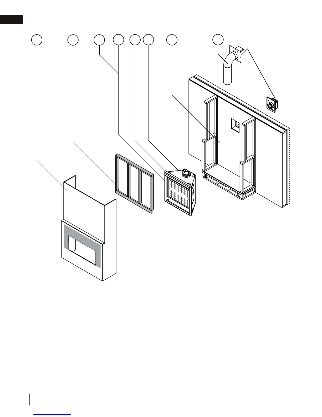
1.2 installation overview
10
9
7
6
4
3
2
Safety Barrier
5
Recommended installation steps:
1. Determine venting requirements before deciding the final location of the appliance.
2. Install rough framing (refer to “rough framing” section).
3. Place the appliance in its final position.
4. Install nailing tabs (refer to “nailing tab installation” section).
5. Install appliance venting (refer to “venting installation” section).
6. Install all electrical wirings (refer to “electrical information” section).
7. Install gas lines (refer to “gas installation” section).
8. Test appliance.
9. Complete framing (refer to “finish framing” section).
10. Finishing (refer to “finishing” section).
6
W415-1793 / A / 05.07.18

general information
roof joist. If the appliance is installed directly on carpeting, vinyl tile or other combustible material other than wood fl ooring, the
WARNING
!
• Always light the pilot whether for the first time or if the gas supply has run out, with the glass door opened
or removed.
• Provide adequate clearance for servicing and operating the appliance.
• Provide adequate ventilation.
• Never obstruct the front opening of the appliance.
• Objects placed in front of the appliance must be kept a minimum of 48” (121.9cm) from the front face of
the appliance.
• Surfaces around and especially above the appliance can become hot. Avoid contact when appliance is
operating.
• Fire risk. Explosion hazard.
• High pressure will damage valve. Disconnect gas supply piping before pressure testing gas line at test
pressures above 1/2 PISG (35mb). Close the manual shut-off valve before pressure testing gas line at test
pressures equal to or less than 1/2 PISG (35mb).
• Use only Wolf Steel approved optional accessories and replacement parts with this appliance using nonlisted accessories (blowers, doors, louvres, trims, gas components, venting components, etc.) could result
in a safety hazard and will void the warranty and certification.
• The appliance must not be operated at temperatures below freezing (32ºF/0ºC). Allow the appliance to
warm to above freezing prior to operation.
EN
THIS GAS APPLIANCE MUST BE INSTALLED AND SERVICED BY A QUALIFIED INSTALLER to conform with local
codes. Installation practices vary from region to region and it is important to know the specifi cs that apply to your area, for
example in the state of Massachusetts:
• This product must be installed by a licensed plumber or gas fi tter when installed within the commonwealth of
Massachusetts.
• The appliance damper must be removed or welded in the open position prior to installation of an appliance insert or gas
log.
• The appliance off valve must be a “T” handle gas cock.
• The fl exible connector must not be longer than 36 inches (0.9m).
• A carbon monoxide detector is required in all rooms containing gas fi red appliances.
• The appliance is not approved for installation in a bedroom or bathroom unless the unit is a direct vent sealed
combustion product.
The installation must conform with local codes or, in absence of local
codes, the National Gas and Propane Installation Code CSA B149.1
in Canada, or the National Fuel Gas Code, ANSI Z223.1 / NFPA 54
in the United States. Suitable for mobile home installation if installed
in accordance with the current standard CAN/CSA Z240MH Series,
for gas equipped mobile homes, in Canada or ANSI Z223.1 and
NFPA 54 in the United States.
The appliance and its individual shutoff valve must be disconnected
from the gas supply piping system during any pressure testing
of that system at test pressures in excess of 1/2 psig (35 mb).
The appliance must be isolated from the gas supply piping system by closing its individual manual shutoff valve during any
pressure testing of the gas supply piping system at test pressures equal to or less than 1/2 psig (35 mb). When installed
with a blower or fan, the junction box must be electrically connected and grounded in accordance with local codes. In the
absence of local codes, use the current CSA C22.1 Canadian Electrical Code in Canada or the ANSI / NFPA 70 National
Electric Code in the United States. In the case where the blower is equipped with a power cord, it must be connected into a
properly grounded receptacle. The grounding prong must not be removed from the cord plug.
The following does not apply to inserts; as long as the required clearance to combustibles is maintained, the most desirable
and benefi cial location for an appliance is in the center of a building, thereby allowing the most effi cient use of the heat
created. The location of windows, doors and, the traffi c fl ow in the room where the appliance is to be located should be
considered. If possible, you should choose a location where the vent will pass through the house without cutting a fl oor or
www.ncertied.org
We suggest that our gas
hearth products be installed
and serviced by professionals
who are certied in the U.S.
by the National Fireplace
®
Institute
(NFI) as NFI Gas
Specialists
appliance shall be installed on a metal or wood panel extending the full width and depth, unless otherwise tested.
W415-1793 / A / 05.07.18
7
EN
To convert from one gas to another, consult your Authorized dealer/distributor.
SAMPLE
general information
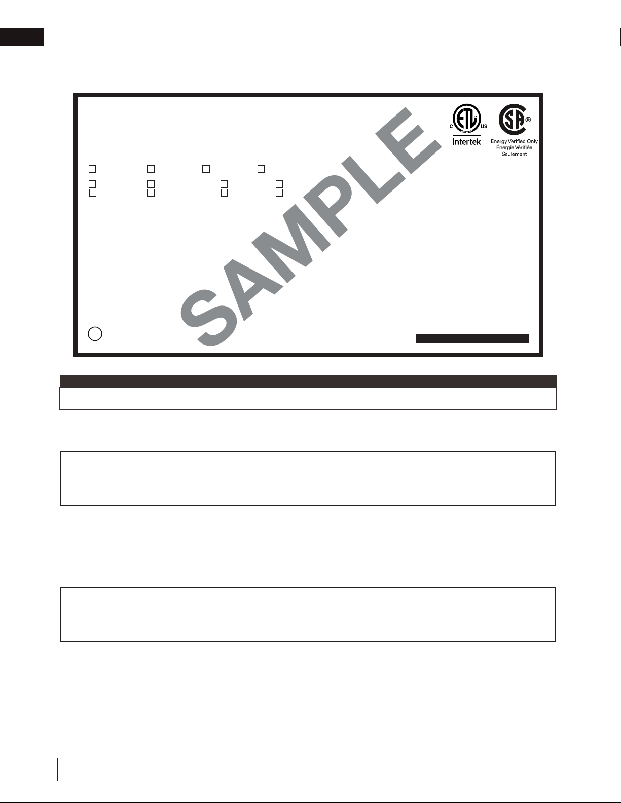
1.3 rating plate information
This illustration is for reference only. Refer to the rating plate on the appliance for accurate information.
Certified to Canadian and American National Standards: CSA 2.22-2016 / ANSI Z21.50-2016 for Vented Decorative Gas Appliances
Certifié selon les normes Nationales Canadiennes et Américaines: CSA 2.22-2016 / ANSI Z21.50-2016 pour les Appareils à gaz décoratif à évacuation
Direct vent, vented gas fireplaces. Approved for bedroom, bathroom and bed-sitting room installation. Suitable for mobile home installation, if installed in accordance with the current
standard CAN / CSA Z240MH Series gas equipped mobile homes in Canada, or, in the United States, the Manufactured Home Construction and Safety Standard, Title 24 CFR, Part
3280. When this US Standard is not applicable, use the Standard for Fire Safety Criteria for Manufactured Home Installations, Sites and Communities, ANSI / NFPA 501A. This appliance
must be installed in accordance with local codes, if any; if none, follow the current ANSI Z223.1 or CSA B149. For use with barrier W565-0144. Follow installation instructions.
Foyer à gaz ventilé. Homologué pour installation dans une chambre à coucher, une salle de bain et un studio. Approprié pour installation dans une maison mobile si son installation
conforme aux exigences de la norme CAN / CSA Z240MH Séries de maisons mobile équipées au gaz en vigueur au Canada, ou, aux États-Unis selon la norme 24 CFR, Part 3280,
Manufactured Home Construction and Safety Standard. Dans le cas ou cette norme d’États-Unis n’est pas pertinentes, utiliser la norme NFPA 501A, Fire Safety Criteria for Manufactured
Home Installations, Sites and Communities. Installer l’appareil selon les codes ou règlements locaux ou, en l’absence de tels règlements, selon les codes d’installation ANSI Z223.1 ou
CSA B149 en vigueur. Utiliser uniquement avec l’écran W565-0144. Suivre les instructions d’installation.
9700539 (WSL) 4001658 (NAC) 4001657 (NGZ) 4001659 (WUSA)
GX70NT CX70NT GX70PT CX70PT
GX70NTE CX70NTE GX70PTE CX70PTE
Altitude
Input
Reduced Input
P4
Manifold Pressure: 3.5” w.c. (NG)
Minimum Supply Pressure: 4.5” w.c. (NG)
Maximum Supply Pressure: 7”* w.c. (NG)
Pression au Collecteur: 3,5” d’une colonne d’eau (GN)
Pression d’Alimentation Min.: 4,5” d’une colonne d’eau (GN)
Pression d’Alimentation Max.: 7”* d’une colonne d’eau (GN)
*Maximum inlet pressure not to exceed 13”.
Minimum clearance to combustible materials:
Sides & back: per stand spacers for framing and finishing
materials. For non-combustible framing and finishing materials,
see installation manual.
Top 6 3/4”
Floor 0”
Sides 3”
Back 0”
Vent top 3”
Vent sides & bottom 1”
Mantel 10 1/2”*
WOLF STEEL LTD. 24 Napoleon Road, Barrie, ON, L4M 0G8 Canada
35,000 BTU/h
21,000 BTU/h
60.0%
*Maximum horizontal extension: 2”. See installation manual for
greater extensions, minimum vent lengths and maximum vent
lengths.
MODEL / MODÈLE
0-4500ft (0-1370m)
Pression d’Alimentation Min.: 11” d’une colonne d’eau (P)
Pression d’Alimentation Max.: 13”* d’une colonne d’eau (P)
*Pression d’alimentation maximale ne devait pas dépasser 13”.
Dégagements minimaux des matériaux combustibles:
Côtés et arrière: selon les espaceurs de dégagements pour les
matériaux d’ossature selon le manual du propriétaire pour les
Recessed depth 18” Profondeur d’encastré 18”
*L’extension horizontale maximale: 2”. Référez au manuel d’installation
pour des extensions plus grandes, les longueurs d’évacuation minimaux et
32,000 BTU/h
26,000 BTU/h
Minimum Supply Pressure: 11” w.c. (P)
Maximum Supply Pressure: 13”* w.c. (P)
Pression au Collecteur: 10” d’une colonne d’eau (P)
Alimentation
Alimentation Réduite
60.2%
Manifold Pressure: 10” w.c. (P)
matériaux de finition.
Dessus 6 3/4”
Plancher 0”
Dessus du conduit d’évent 3”
Côtés et dessous du conduit d’évent 1”
Tablette 10 1/2”*
VENTED DECORATIVE GAS APPLIANCE: NOT A SOURCE OF
HEAT, NOT INTENDED FOR USE AS A HEATING APPLIANCE,
NOT FOR USE WITH SOLID FUEL.
APPAREIL À GAZ DÉCORATIF À ÉVACUATION: N’EST PAS
Élévation
UNE SOURCE DE CHALEUR; N’EST PAS DESTINÉ À ÈTRE
UTILISÉ COMME UN APPAREIL DE CHAUFFAGE; NE
P4
CONVIENT PAS AUX COMBUSTIBLES SOLIDES.
FOR USE WITH GLASS DOORS CERTIFIED WITH THIS APPLIANCE ONLY.
POUR UTILISATION UNIQUEMENT AVEC LES PORTES EN VERRE
CERTIFIÉES AVEC L’APPAREIL.
WARNING: Do not add any material to the appliance which will come in contact with the
flames, other than that supplied by the manufacturer with the appliance.
AVERTISSEMENT: N’ajoutez pas à cet appareil aucun matériau devant entretien
contact avec les flammes autre que celui qui est fourni avec cet appareil par le fabricant.
The appliance must be vented using the appropriate Napoleon vent kits. See installation
manual for venting specifications. Proper reinstallation and resealing is necessary after servicing
the vent-air intake system.
L’appareil doit être ventilé à l’aide de l’ensemble d’évacuation propre à Napoleon. Référez au
Côtés 3”
manuel d’installation pour les spécifications d’évacuation. Il est nécessaire de bien réinstaller et
Arrière 0”
resceller l’évacuation après avoir executer l’entertien du système de prise d’air.
Electrical rating: 115V, 60HZ. Less than 12 amperes.
Spécifications électriques: 115V, 60HZ. Moins de 12 ampère.
maximum.
Serial Number / N° de Série:
GX70
Insert
testing
agency
logo
REFERENCE# 161746
W385-2070 / D
note:
The rating plate must remain with the appliance at all times. It must not be removed.
1.4 mobile home installation
This appliance must be installed in accordance with the manufacturer’s instructions and the Manufactured
Home Construction and Safety Standard, Title 24 CFR, Part 3280, in the United States or the Mobile Home
Standard, CAN/CSA Z240 MH Series, in Canada. This appliance is only for use with the type(s) of gas
indicated on the rating plate.
This mobile/manufactured home listed appliance comes factory equipped with a means to secure the appliance. Built
in appliances are equipped with 1/4” (6.4mm) diameter holes located in the front left and right corners of the base.
Use appropriate fasteners, inserted through the holes in the base to secure. For free standing products contact your
local authorized dealer / distributor for the appropriate securing kit. For mobile home installations, the appliance must
be fastened in place. It is recommended that the appliance be secured in all installations. Always turn off the pilot and
the fuel supply at the source, prior to moving the mobile home. After moving the mobile home and prior to lighting the
appliance, ensure that the logs are positioned correctly.
This appliance is certifi ed to be installed in an aftermarket permanently located, manufactured (mobile) home,
where not prohibited by local codes.
This appliance is only for use with the type of gas indicated on the rating plate. This appliance is not convertible
for use with other gases, unless a certifi ed kit is used.
Conversion Kits
This appliance is fi eld convertible between Natural Gas (NG) and Propane (P).
8
W415-1793 / A / 05.07.18
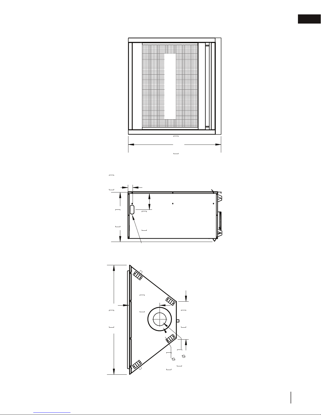
1.5 dimensions
SAFETY BARRIER
879mm
34 5/8”
general information
FRONT VIEW
EN
1 15/16"
50mm
470mm
890mm
35"
18 1/2"
182mm
GAS
INLET
288mm
7 3/16"
11 5/16"
11 13/16"
299mm
RIGHT SIDE VIEW
TOP VIEW
127mm
8"
5"
W415-1793 / A / 05.07.18
9
203mm
EN
WARNING
GD420
GD430
venting requirements
2.0 venting requirements
!
• Risk of fi re. Maintain specifi ed air space clearances to vent pipe and appliance.
• The vent system must be supported every 3’(0.9m) for both vertical and horizontal runs. Use support ring
assembly W010-0067 or equivalent non-combustible strapping to maintain the minimum clearance to
combustibles for both vertical and horizontal runs. Spacers are attached to the inner pipe at predetermined
intervals to maintain an even air gap to the outer pipe. This gap is required for safe operation. A spacer is
required at the start, middle, and end of each elbow to ensure this gap is maintained. These spaces must
not be removed.
This appliance uses a 5” (127mm) exhaust / 8” (203.2mm) air intake vent pipe system. Refer to the
section applicable to your installation.
For safe and proper operation of the appliance follow the venting instructions exactly. Deviation from the
minimum vertical vent length can create diffi culty in burner start-up and/or carboning. Under extreme vent
confi gurations, allow several minutes (5-15) for the fl ame to stabilize after ignition. Although not a requirement,
it is recommended for vent lengths that pass through unheated spaces (attics, garages, crawl spaces) be
insulated with the insulation wrapped in a protective sleeve to minimize condensation. Provide a means for
visually checking the vent connection to the appliance after the appliance is installed. Use a fi restop, vent pipe
shield or attic insulation shield when penetrating interior walls, fl oor or ceiling.
The vent terminal may be painted with a high temperature paint to match exterior colours. Use an outdoor paint
suitable for 400°F (200°C). Application and performance of paint is the consumer’s responsibility. Spot testing is
recommended.
note:
If for any reason the vent air intake system is disassembled; reinstall per the instructions provided for the
initial installation.
This appliance must be installed with a continuous connection of exhaust and air intake vent pipes. Utilizing
alternate constructions, such as a chimney as part of the vent system, is not permitted.
Use only Wolf Steel, Simpson Dura-Vent, Selkirk Direct Temp, American Metal Amerivent or Metal-Fab venting
components. Minimum and maximum vent lengths, for both horizontal and vertical installations, clearances from
vent pipes to combustibles and air terminal locations as set out in this manual apply to all vent systems and
must be adhered to. For Simpson Dura-Vent, Selkirk Direct Temp, American Metal Amerivent and Metal-Fab,
follow the installation procedure provided with the venting components. A starter adaptor must be used with the
following vent systems and may be purchased from the corresponding supplier:
Vent
Manufacturer
Duravent W175-0170 Wolf Steel www.duravent.com
Amerivent 5DSC-N2 American Metal www.americanmetalproducts.com
Direct Temp 5DT-AA Selkirk www.selkirkcorp.com
SuperSeal 5DNA Metal-Fab www.mtlfab.com
For vent systems that provide seals on the inner exhaust fl ue, only the outer air intake joints must be sealed using
a red high temperature silicone (RTV). This same sealant may be used on both the inner exhaust and outer intake
vent pipe joints of all other approved vent systems except for the exhaust vent pipe connection to the appliance
fl ue collar which must be sealed using the black high temperature sealant Mill Pac.
When using Wolf Steel venting components, use only approved Wolf Steel rigid / fl exible components with the
This template must be used in conjunction with templates 7.2.1 or 7.2.2, depending on termina-
following termination kits: wall terminal kit GD422-1, GD422R-2, or 1/12 to 7/12 pitch roof terminal kit GD410,
tion shape (i.e. round, or round and square). See appropriate templates folder.
8/12 to 12/12 roof terminal kit GD411, fl at roof terminal kit GD412 or periscope kit GD401 (for wall penetration
below grade). With fl exible venting, in conjunction with the various terminations, use either the 5 foot (1.5m) vent
kit
or the 10 foot (3.1m) vent kit
Starter Adapter Part
Number
Supplier Website
.
All vent measurements start at the base of the air collar of the appliance.
10
W415-1793 / A / 05.07.18
• The vent system must be supported every 3’(0.9m) for both vertical and horizontal runs. Use support ring
assembly W010-0067 or equivalent non-combustible strapping to maintain the minimum clearance to
combustibles for both vertical and horizontal runs. Spacers are attached to the inner pipe at predetermined
intervals to maintain an even air gap to the outer pipe. This gap is required for safe operation. A spacer is
required at the start, middle, and end of each elbow to ensure this gap is maintained. These spaces must
not be removed.
This appliance uses a 5” (127mm) exhaust / 8” (203.2mm) air intake vent pipe system. Refer to the
section applicable to your installation.
For safe and proper operation of the appliance follow the venting instructions exactly. Deviation from the
minimum vertical vent length can create diffi culty in burner start-up and/or carboning. Under extreme vent
confi gurations, allow several minutes (5-15) for the fl ame to stabilize after ignition. Although not a requirement,
it is recommended for vent lengths that pass through unheated spaces (attics, garages, crawl spaces) be
insulated with the insulation wrapped in a protective sleeve to minimize condensation. Provide a means for
visually checking the vent connection to the appliance after the appliance is installed. Use a fi restop, vent pipe
shield or attic insulation shield when penetrating interior walls, fl oor or ceiling.
The vent terminal may be painted with a high temperature paint to match exterior colours. Use an outdoor paint
suitable for 400°F (200°C). Application and performance of paint is the consumer’s responsibility. Spot testing is
recommended.
For vent systems that provide seals on the inner exhaust fl ue, only the outer air intake joints must be sealed using
a red high temperature silicone (RTV). This same sealant may be used on both the inner exhaust and outer intake
vent pipe joints of all other approved vent systems except for the exhaust vent pipe connection to the appliance
fl ue collar which must be sealed using the black high temperature sealant Mill Pac.
For optimum fl ame appearance and appliance performance, keep the vent length and number of elbows to
(31.8mm) air gap all around between the inner liner and outer liner is required for safe operation.
Vent
Manufacturer
Starter Adapter Part
Number
Supplier Website
Duravent W175-0170 Wolf Steel www.duravent.com
Amerivent 5DSC-N2 American Metal www.americanmetalproducts.com
Direct Temp 5DT-AA Selkirk www.selkirkcorp.com
SuperSeal 5DNA Metal-Fab www.mtlfab.com
Use only Wolf Steel, Simpson Dura-Vent, Selkirk Direct Temp, American Metal Amerivent or Metal-Fab venting
components. Minimum and maximum vent lengths, for both horizontal and vertical installations, clearances from
vent pipes to combustibles and air terminal locations as set out in this manual apply to all vent systems and
must be adhered to. For Simpson Dura-Vent, Selkirk Direct Temp, American Metal Amerivent and Metal-Fab,
follow the installation procedure provided with the venting components. A starter adaptor must be used with the
following vent systems and may be purchased from the corresponding supplier:
If for any reason the vent air intake system is disassembled; reinstall per the instructions provided for the
initial installation.
This appliance must be installed with a continuous connection of exhaust and air intake vent pipes. Utilizing
alternate constructions, such as a chimney as part of the vent system, is not permitted.
note:
This template must be used in conjunction with templates 7.2.1 or 7.2.2, depending on termina-
tion shape (i.e. round, or round and square). See appropriate templates folder.
a minimum.
The air terminal must remain unobstructed at all times. Examine the air terminal at least once a year
to verify that it is unobstructed and undamaged.
Rigid and fl exible venting systems must not be combined. Different venting manufacturer components
must not be combined.
These vent kits allow for either horizontal or vertical venting of the appliance. The maximum allowable horizontal
run is 20 feet (6.1m). The maximum allowable vertical vent length is 40 feet (12.2m). The maximum number of
vent connections is two horizontally or three vertically (excluding the appliance and the air terminal connections)
when using fl exible venting.
Horizontal runs may have a 0” (0mm) rise per foot/meter however for optimum performance it is recommended
that all horizontal runs have a minimum 1/4” (21mm) rise per foot/meter using fl exible venting. For safe and
proper operation of the appliance, follow the venting instructions exactly.
A terminal shall not terminate directly above a sidewalk or paved driveway which is located between two single
family dwellings and serves both dwellings. Local codes or regulations may require different clearances.
Do not allow the inside liner to bunch up on horizontal or vertical runs and elbows. Keep it pulled tight. A 1¼”
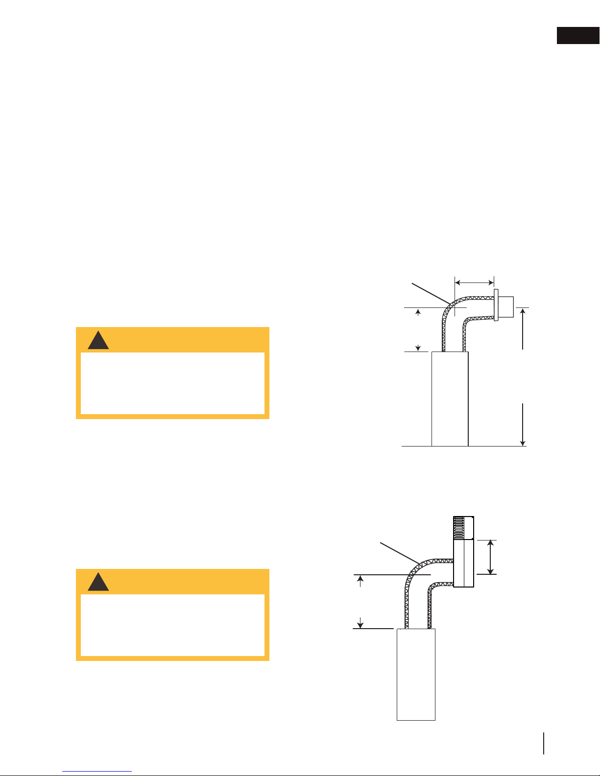
2.1 typical venting installation
WARNING
!
• The first 2 feet of outer 8” (203mm)
diameter vent pipe from the appliance must be wrapped in the
1” (25mm) thick insulation sleeve
(supplied).
base of air collar
venting requirements
18" (45.7cm)
maximum
mylar sleeve
15 1/8"
(38.4cm)
EN
49 3/4"
(126.4cm)
Special vent installation (periscope termination)
Use the periscope kit to locate the air termination above grade. The periscope must be installed so that when
final grading is completed, the bottom air slot is located a minimum 12” (30.5cm) above grade. The maximum
allowable vent length is 10’ (3m) for a fireplace and 8’ (2m) for a stove.
WARNING
!
• The first 2 feet of outer 8” (203mm)
diameter vent pipe from the appliance must be wrapped in the
1” (25mm) thick insulation sleeve
(supplied).
mylar sleeve
30" (76.2cm)
minimum
base of air collar
(30.5cm)
minimum
to grade
12"
W415-1793 / A / 05.07.18
11
EN
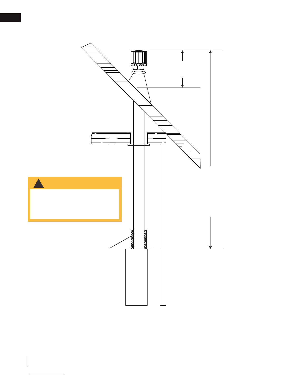
venting requirements
16" (40.6cm)
MINIMUM
WARNING
!
• The first 2 feet of outer 8” (203mm)
diameter vent pipe from the appliance must be wrapped in the
1” (25mm) thick insulation sleeve
(supplied).
mylar sleeve
40 FT (12M)
MAXIMUM
3 FT (1M)
MINIMUM
base of air collar
* Refer to “venting requirements” and “venting installation” sections.
12
W415-1793 / A / 05.07.18
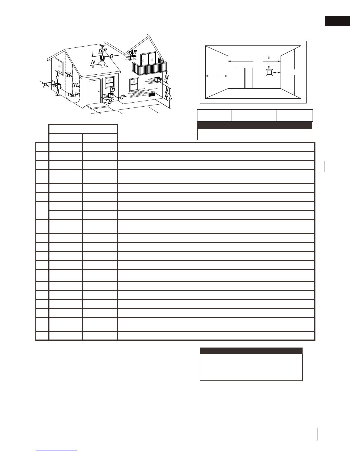
2.2 minimum air terminal location clearances
Covered balcony applications ††*
venting requirements
Q
S
R
P
G
EN
Q
= 3 feet
MIN
(0.9m)
INSTALLATIONS
CANADA U.S.A.
12” (30.5cm) 12” (30.5cm) Clearance above grade, veranda porch, deck or balcony.
A
Δ
12” (30.5cm)
B
12” (30.5cm)* 12” (30.5cm)* Clearance to permanently closed windows.
C
D
E
F
G
H
I
J
K
L
M
18”
(45.7cm)**
12” (30.5cm)** 12” (30.5cm)** Clearance to unventilated soffi t.
0” (0mm) 0” (0mm) Clearance to an outside corner wall.
0” (0mm)*** 0” (0mm)***
2” (51mm)*** 2” (51mm)*** Clearance to an inside combustible corner wall or protruding combustible obstructions (vent chase, etc.).
3’(0.9m) 3’(0.9m)****
3’ (0.9m) 3’ (0.9m)**** Clearance to a service regulator vent outlet.
12” (30.5cm) 9” (229mm) Clearance to a non-mechanical air supply inlet to the building or a combustion air inlet to any other appliance.
6’ (1.8m) 3’ (0.9m) † Clearance to a mechanical air supply inlet.
7’ (2.1m) ‡ 7’ (2.1m) **** Clearance above a paved sidewalk or paved driveway located on public property.
12” (30.5cm)†† 12” (30.5cm)**** Clearance under a veranda, porch or deck.
9” (229mm) ΔClearance to windows or doors that open.
18”
(45.7cm)**
Vertical clearance to ventilated soffi ts located above the terminal within a horizontal distance of 2’
(0.6m) from the center line of the terminal.
Clearance to an inside non-combustible corner wall or protruding non-combustible obstructions (chimney, etc.).
Clearance to each side of the center line extended above the meter / regulator assembly to a maximum vertical distance of 15’ (4.6m).
note:
Wall terminals are for illustration purposes only. Size and
shapes may vary.
R
= 2 x
MAX
Q
ACTUAL
R
MAX
≤ 15 feet
(4.6m)
16” (40.6cm) 16” (40.6cm) Clearance above the roof.
N
2’ (0.6m)†* 2’ (0.6m) †* Clearance from an adjacent wall including neighbouring buildings.
O
8’ (2.4m) 8’ (2.4m)
P
3’ (0.9m) 3’ (0.9m) See chart for wider wall dimensions.
Q
6’ (1.8m) 6’ (1.8m)
R
12” (30.5cm) 12” (30.5cm) Clearance under a covered balcony
S
Δ The terminal shall not be located less than 6 feet under a window that opens on a horizontal plane in a structure with three walls and a roof.
* Recommended to prevent condensation on windows and thermal breakage
** It is recommended to use a heat shield and to maximize the distance to vinyl clad soffi ts.
*** The periscope requires a minimum 18 inches clearance from an inside corner.
**** This is a recommended distance. For additional requirements, check local codes.
† 3 feet above if within 10 feet horizontally.
‡ A vent shall not terminate where it may cause hazardous frost or ice accumulations on adjacent property surfaces.
†† Permitted only if the veranda, porch, or deck is fully open on a minimum of two sides beneath the fl oor.
†* Recommended to prevent recirculation of exhaust products. For additional requirements, check local codes.
††* Permitted only if the balcony is fully open on a minimum of one side.
Roof must be non-combustible without openings.
See chart for deeper wall dimensions. The terminal shall not be installed on any wall that has an
opening between the terminal and the open side of the structure.
note:
Clearances are to be in accordance with local
installation codes and the requirements of the gas
supplier. In their absence, clearances are to be as
listed above and are based on national codes.
W415-1793 / A / 05.07.18
13
EN
venting requirements
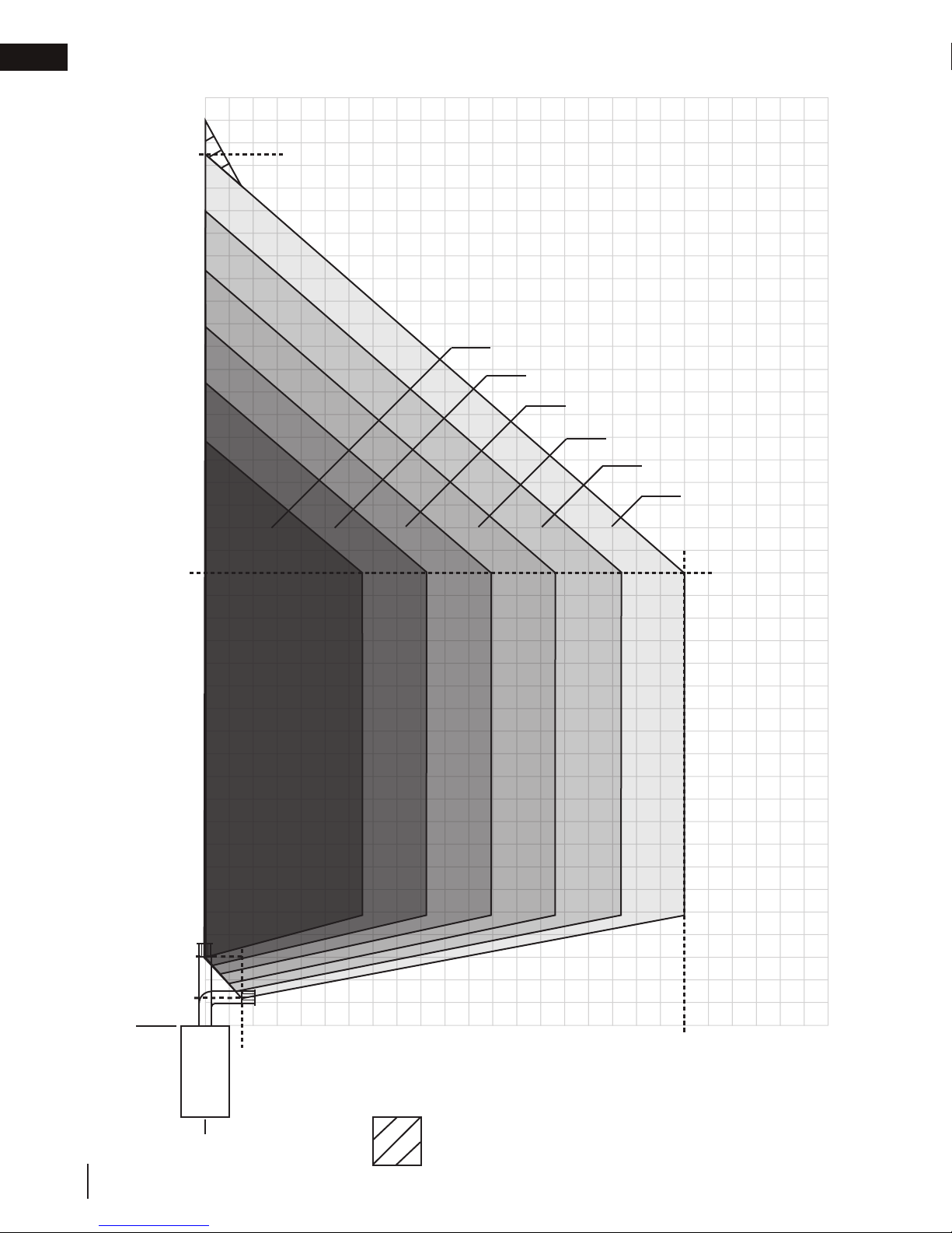
2.3 all terminations
40’
38 1/2’
(462”)
V+H ≤ 40 ft. (For longer vent runs, a power
vent is required).
H ≤ 20 ft.
V + H are measured from the centre of vent
elbows. Elbows are considered as 90º.
Two 45º elbows = One 90º elbow.
V
20’
30’
15’
1-6 elbow zone
1-5 elbow zone
1-4 elbow zone
1-3 elbow zone
1-2 elbow zone
1 elbow zone
10’
5’
3’ min.
(36”)
1 1/4’ min.
(15 1/8”)
0’
Base of
air collar
14
W415-1793 / A / 05.07.18
1 1/2’
(18”)
0’
5’
10’
15’
20’
H
Vertical termination only.
No horizontal termination allowed.
25’

!
WARNING
3.0 rough framing
Do not put objects in front of the appliance
(minimum distance of 4 feet)*
note:
When using optional fi nishing accessories, the framing dimensions and fi nishing materials may differ from
what is outlined in the section below; refer to the leafl et instructions supplied in the accessory kit for specifi c
framing and fi nishing specifi cations.
• Risk of fi re!
• In order to avoid the possibility of exposed insulation or vapour barrier coming in contact with the appliance
body, it is recommended that the walls of the appliance enclosure be “fi nished” (i.e. drywall / sheetrock),
as you would fi nish any other outside wall of a home. This will ensure that clearance to combustibles is
maintained within the cavity.
• Do not notch the framing around the appliance stand offs. Failure to maintain air space clearance may cause
over heating and fi re. Prevent contact with sagging or loose insulation or framing and other combustible
materials. Block opening into the chase to prevent entry of blown-in insulation. Make sure insulation and
other materials are secured.
• When constructing the enclosure, allow for fi nishing material thickness to maintain clearances. Framing or
fi nishing material closer than the minimums listed must be constructed entirely of non-combustible materials.
Materials consisting entirely of steel, iron, brick, tile, concrete, slate, glass or plasters, or any combination
thereof are suitable. Materials that are reported as passing ASTM E136, standard test method for behaviour
of materials in a vertical tube furnace at 1382ºF (750ºC) and UL763 shall be considered non-combustible
materials.
• Minimum clearance to combusibles must be maintained or a serious fi re hazard could result.
• The appliance requires a minimum enclosure height. Measure from the appliance base.
• If steel stud framing kits with cement board are provided, or specifi ed in the installation instructions, they
must be installed.
• If specifi ed in the installation instruction, fi nishing must be done using a non-combustible board, ceramic tile,
marble, etc. Do NOT use wood or drywall. Any fi re rated drywall is not acceptable.
rough framing
EN
3.1 minimum framing dimensions
SIDE WALL
35 1/2”
(90.2cm)
18 9/16”
(47cm)
6”
(152mm)
(90.2cm)
47 7/8”
(122.6cm)
33 7/8”
86cm)
35 1/2”
W415-1793 / A / 05.07.18
15

34 7/8"
[88.6cm]
1" [25mm]
Firestop
assembly
Steel stud frame
[51mm]
49 3/4"
[126.4cm]
minimum
plus ride *
7 1/2"
[191mm]
42 3/8"
[107.6cm]
59 1/2"
[151.1cm]
ceiling
EN
rough framing
3.2 minimum clearance to combustible enclosures
note:
Vent Sections
When passing through a wall, use firestop spacer W010-1800 (supplied).
When passing through a ceiling, use firestop spacer W500-0028 (not supplied).
1" [25mm] minimum all sides for vertical venting
above enclosure ceiling. When passing through a
ceiling, use firestop W500-0028 (not supplied).
1½" [38mm] minimum all sides for vertical venting
inside the enclosure.
78"
[198.1cm]
ceiling
[151.1cm]
enclosure
Non-combustible
59 1/2"
height
Combustible
5 3/4"
[146mm]
Mylar
sleeve
material
6 3/4"
[171.5mm]
Steel stud frame
Non-combustible
Brick
3"
[76mm]
to top
2"
[51mm] to
sides / bottom
Firestop
assembly
0” [0mm] if non-combustible
finishing material is used
such as brick and stone.
16
49 3/4"
[126.4cm]
minimum
plus rise *
34 7/8"
[88.6cm]
1" [25mm]
* Refer to “venting requirements” and “venting installation” sections.
** Clearances within the enclosure may be higher (refer to “minimum framing dimensions” section).
W415-1793 / A / 05.07.18

rough framing
note:
For heavier finishing materials such as marble, we recommend adding extra support to the frame. Ensure
there is adequate floor support for the appliance and finishing material.
Before framing your appliance, determine vent requirements before deciding the final location of the appliance.
After rough framing, place the appliance in its final position.
EN
Ref Minimum rough framing dimensions
A
B
* Based on 1/2” finishing material thickness.
A
B
19”* (48.3cm)
35 1/2” (90.2cm)
W415-1793 / A / 05.07.18
17

EN
!
WARNING
4.0 venting installation
venting installation
• Ensure to unpack all loose materials from inside the fi rebox prior to connecting the gas and electrical supply
• If your appliance is supplied with a remote, ensure the remote receiver is in the “OFF” position prior
to connecting the gas and electrical supply to the appliance.
• For safe and proper operation of the appliance, follow the venting instructions exactly.
• The appliance exhaust fl ue collar must be sealed using Mill Pac. All exhaust and intake vent pipe joints
must be sealed using red RTV high temp silicone sealant (W573-0002) (not supplied) or black high temp Mill
Pac (W573-0007) (not supplied).
• If using pipe clamps to connect rigid vent components, a minimum of 3 screws must also be used to ensure
the connection cannot slip off.
• Do not clamp the fl exible vent pipe.
• Risk of fi re, explosion, or asphyxiation. Improper support of the entire venting system may allow vent to sag
and separate. Use vent run supports and connect vent sections per installation instructions.
• Risk of fi re, do not allow loose materials or insulation to touch the vent pipe. Remove insulation to allow for the
installation of the attic shield and to maintain clearances to combustibles.
• Do not fi ll the space between the vent pipe and enclosure with any type of material. Do not pack insulation
or combustibles between ceiling fi restops. Always maintain specifi ed clearances around venting and fi restop
systems. Install wall shields and fi restops as specifi ed. Failure to keep insulation or other materials away from
vent pipe may cause fi re.
For optimum performance, it is recommended that all horizontal runs have a minimum of 1/4" (6mm) rise per foot
using flexible venting. For safe and proper operation of the appliance, follow the venting instructions exactly.
18
W415-1793 / A / 05.07.18

venting installation
between the pipe and the fi restop.
WARNING
This application occurs when venting through a roof. Installation kits for
4.1 horizontal installation
!
• The fi restop assembly must be installed with the vent shield to the top.
• Terminals must not be recessed into a wall or siding more than the depth of the return fl ange of the mounting
plate.
EN
This application occurs when venting through an exterior
wall. Having determined the correct height for the air
terminal location, cut and frame a hole in the exterior wall,
as illustrated, to accommodate the fi restop assembly. Dry
fi t the fi restop assembly before proceeding to ensure the
brackets on the rear surface fi t to the inside surface of the
horizontal framing.
The length of the vent shield may be cut shorter for
combustible walls that are less than 8 1/2” (215.9mm)
thick but the vent shield must extend the full depth of the
combustible wall.
note:
Do not fi ll the air space between the fi restop spacer and the
exterior wall with any type of insulating material (i.e. spray foam).
A. Apply a bead of caulking (not supplied) around the outer edge of
the hole of the fi restop assembly, fi t the fi restop assembly to the
hole and secure using 4 screws.
B. Once the vent pipe is installed in its fi nal position, apply red RTV silicone (W573-0002) (not supplied)
4.2 vertical installation
various roof pitches are available from your authorized dealer / distributor.
See the “accessories” section to order specifi c kits required.
A. Determine the air terminal location, cut and frame a square opening,
as illustrated, in the ceiling and the roof to provide the minimum 1"
(25mm) clearance between the vent pipe and any combustible material.
Try to center the vent pipe location midway between two joists to
prevent having to cut them. Use a plumb bob to line up the center of
the openings. A vent pipe shield will prevent any materials such as
insulation, from fi lling up the 1" (25mm) air space around the pipe. Nail
headers between the joist for extra support.
B. Apply a bead of caulking (not supplied) to the framework or to the
Wolf Steel vent pipe shield plate or equivalent (in the case of a fi nished
ceiling), and secure over the opening in the ceiling. A fi restop must be
placed on the bottom of each framed opening in a roof or ceiling that
the venting system passes through. Apply a bead of caulking all around
and place a fi restop spacer over the vent shield to restrict cold air from
being drawn into the room or around the fi replace. Ensure that both
spacer and shield maintain the required clearance to combustibles.
Once the vent pipe is installed in its fi nal position, apply red RTV
silicone (W573-0002) (not supplied) between the pipe and the fi restop
assembly.
C. In the attic, slide the vent pipe collar down to cover up the open end
of the shield and tighten. This will prevent any materials, such as
insulation, from fi lling up the 1" (25mm) air space around the pipe.
CAULKING
FIRESTOP
SPACER
CAULKING
14”
ADD
(35.6cm)
VENT
SHIELD
note:
The above is for illustration purposes only. Vents
do not always pass through center of frame.
HEIGHT
HIGH
FINISHING
MATERIAL
Vent Pipe
Shield
underside
Vent
Pipe
Shield
14”
(35.6cm)
WIDE
DETERMINE
THE
CORRECT
HEIGHT
Firestop
of joist
Caulking
Vent
Pipe
Collar
ADD
WIDTH
W415-1793 / A / 05.07.18
19
EN
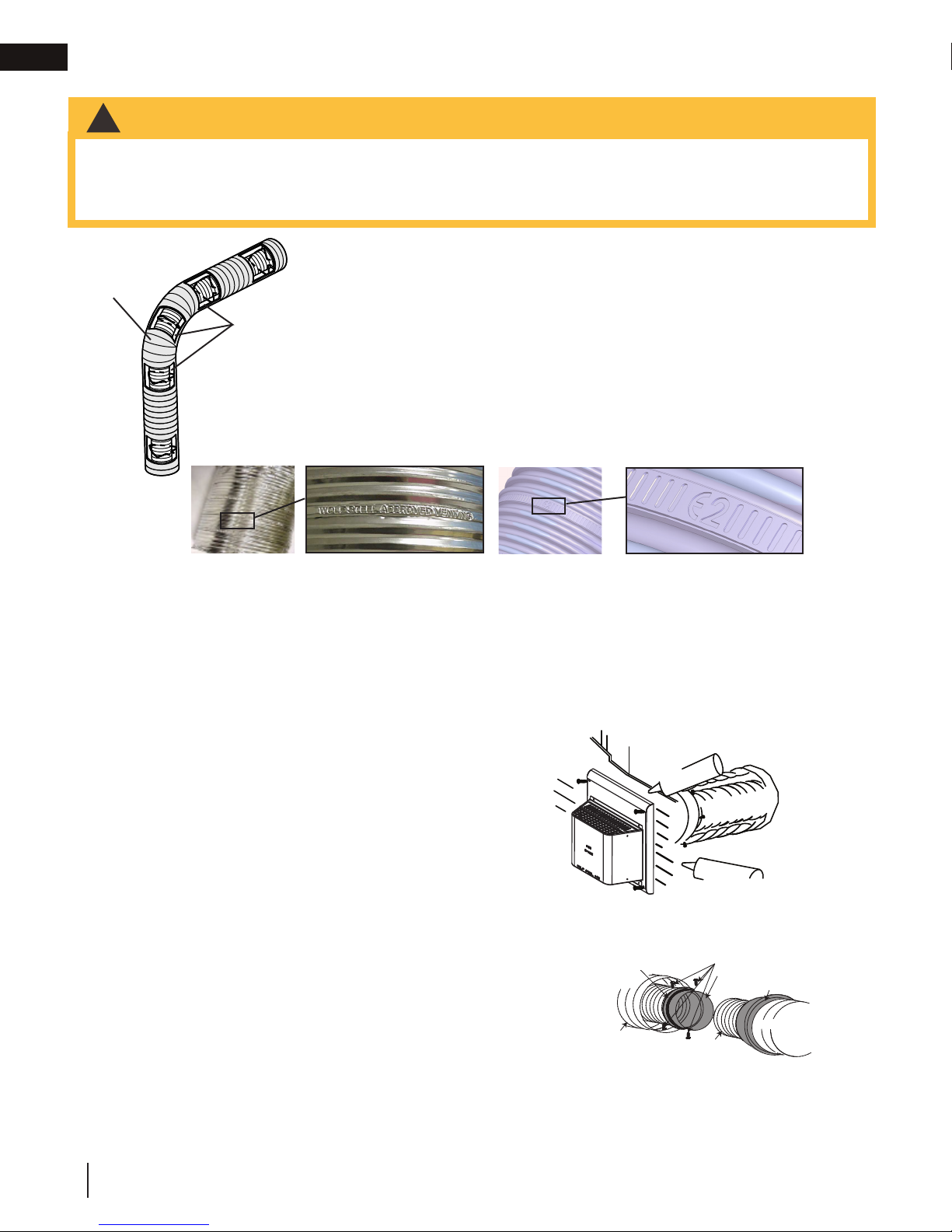
A. Stretch the inner fl ex pipe to the required length taking
ADD FASTENER TYPE
“Wolf Steel Approved Venting” or “E2” as identifi ed by the stamp only on the fl ex pipes.
!
WARNING
venting installation
4.3 using either flexible vent components
• Do not allow the inner fl ex pipe to bunch up on horizontal or vertical runs and elbows. Keep it pulled tight.
• Spacers are attached to the inner fl ex pipe at predetermined intervals to maintain an even air gap to the outer
fl ex pipe. This gap is required for safe operation. A spacer is required at the start, middle, and end of each
elbow to ensure this gap is maintained. These spacers must not be removed.
For safe and proper operation of the appliance, follow the venting instructions
exactly.
Elbow
Spacers
The vent system must be supported approximately every 3 feet (0.9m) for
both vertical and horizontal runs. Use Wolf Steel Ltd. support ring assembly
or equivalent noncombustible strapping to maintain the minimum clearance to
combustibles for both vertical and horizontal runs.
All inner fl ex pipe and outer fl ex pipe joints may be sealed using high temperature
red RTV silicone W573-0002 (not supplied) or the high temperature sealant W5730007 Mill Pac (not supplied). However, the high temperature sealant W573-0007
Mill Pac (not supplied) must be used on the joint connecting the inner fl ex pipe and
the exhaust fl ue collar.
Use only approved fl exible vent pipe kits marked:
When installing using rigid vent components, follow the manufacturer’s installation and vent sealing requirements.
4.3.1 horizontal air terminal installation
into account the additional length needed for the fi nished
wall surface. Apply a heavy bead of the red RTV silicone
(W573-0002) (not supplied) to the inner sleeve of the air
terminal. Slip the vent pipe a minimum of 2” (50.8mm)
over the inner sleeve of the air terminal and secure with a
minimum of 3 screws.
B. Using the outer fl ex pipe, slide over the outer combustion
air sleeve of the air terminal and secure with a minimum
C. Insert the vent pipes through the fi restop maintaining
D. If more vent pipe needs to be used to reach the fi replace,
E. Stove Appliances Only: From inside the house, using
The air terminal mounting plate may be recessed into the
exterior wall or siding no great than the depth of its return
flange.
of 3 screws. Seal using red RTV silicone (W573-0002)
(not supplied).
the required clearance to combustibles. Holding the air
terminal (lettering in an upright, readable position), secure
to the exterior wall and make weather tight by sealing
with caulking (not supplied).
couple them together, as illustrated. The vent system
must be supported approximately every 3 feet (0.9m) for
both vertical and horizontal runs. Use non-combustible
strapping to maintain the minimum clearance to
combustibles.
Caulking
Screws
(Supplied)
Red RTV Silicone
Outer Flex
ADD GRAPHIC
Pipe
Inner Flex
Pipe
2" (50.8mm) Overlap
Red RTV Silicone
Outer Flex Pipe
Screws
Inner Coupler
Outer Coupler
Inner Flex
Pipe
Outer Flex
Pipe
20
W415-1793 / A / 05.07.18

venting installation
temperature red RTV silicone (W573-0002) (not supplied).
ADD FASTENER TYPE
1 1/4” (31.8mm)
TOP VENT - FLEX TOP VENT - RIGID/FLEX
#8 X 1/2”
Self Drilling
Screws
45 VENT - FLEX 45 VENT - RIGID/FLEX
2” (50.8mm)
Overlap
Mill Pac
Sealant
#8 X 1/2”
Self Drilling
Screws
2” (50.8mm)
Overlap
#8 X 1/2”
Self Drilling
Screws
Mill Pac
Sealant
Mill Pac
Sealant
air terminal installation” section.
!
WARNING
4.3.2 vertical air terminal installation
• Maintain a minimum 2” (51mm) space between the air inlet base and the storm collar.
note:
Fastening hardware provided with appropriate roof terminal and liner kits.
A. Fasten the roof support to the roof using 6 screws. The roof support is
optional. In this case, the venting is to be adequately supported using
either an alternate method suitable to the authority having jurisdiction or
the optional roof support.
B. Stretch the inner fl ex pipe to the required length. Slip the inner fl ex
pipe a minimum of 2” (51mm) over the inner pipe of the air terminal
connector and secure with a minimum of three screws, when 4/7, 5/8
and 3/5 venting is used and a minimum of six screws when using 8/10
or 8/11 venting. Seal using a heavy bead of red RTV silicone sealant
(W573-0002) (not supplied).
C. Repeat using the outer fl ex pipe, using a heavy bead of red RTV
silicone sealant (W573-0002) (not supplied) and a minimum of three
screws, when 4/7, 5/8 and 3/5 venting is used and a minimum of six
screws when using 8/10 or 8/11 venting.
D. Thread the air terminal connector / vent pipe assembly down through
the roof. The air terminal must be positioned vertically and plumb.
Attach the air terminal connector to the roof support, ensuring that the
top of the air terminal is 16” (40.6cm) above the highest point that it
penetrates the roof.
E. Remove nails from the shingles, above and to the sides of the air
terminal connector. Place the fl ashing over the air terminal connector
leaving a min. 3/4” (19mm) of the air terminal connector showing above
the top of the fl ashing. Slide the fl ashing underneath the sides and
upper edge of the shingles. Ensure that the air terminal connector is
properly centered within the fl ashing, giving a 3/4” (19mm) margin all
around. Fasten to the roof. Do not nail through the lower portion of the
fl ashing. Make weather-tight by sealing with caulking. Where possible,
cover the sides and top edges of the fl ashing with roofi ng material.
F. Aligning the seams of the terminal and air terminal connector, place the
terminal over the air terminal connector making sure the vent pipe goes
into the hole in the terminal. Secure with a minimum of three screws,
when 4/7, 5/8 and 3/5 venting is used and a minimum of six screws
when using 8/10 or 8/11 venting.
G. Apply a heavy bead of weatherproof caulking 2” (51mm) above the
fl ashing. Install the storm collar around the air terminal and slide down
to the caulking. Tighten to ensure that a weather-tight seal between the
air terminal and the collar is achieved.
H. If more vent pipe needs to be used to reach the appliance, see “horizontal
2” (51mm)
EN
Roof Support
Inner Pipe
Air
Terminal
Connector
Red RTV
Silicone
(W572-0002)
Inner Flex Pipe
Outer Flex Pipe
Air Inlet
Base
Caulking
Sto r m Collar
Weather
Sealant
Flashing
4.3.3 appliance vent connection
A. Install the inner fl ex pipe to the appliance. Secure with a minimum of
three screws when installing 3”/5”, 4”/7” or 5”/8” venting, or six screws
when installing 8”/10” or 8”/11” venting. Seal the joint and screw holes
using Mill Pac sealant (W573-0007) (not supplied).
B. Install the outer fl ex pipe to the appliance. Secure with a minimum of
three screws when installing 3”/5”, 4”/7” or 5”/”8 venting, or six screws
when installing 8”/10” or 8”/11” venting. Seal the joints using high
#8 X 1/2”
Self Drilling
Screws
INSERT
IMAGE HERE
Red RTV
Silicone
Overlap
Mill Pac Sealant
W415-1793 / A / 05.07.18
21
EN
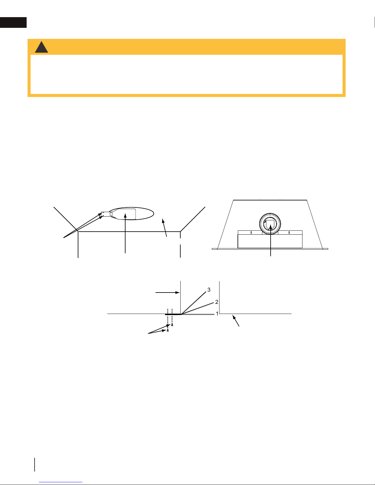
3. Least restriction
venting installation
4.3.4 restricting vertical vents
WARNING
!
• Turn off gas and electrical supply before servicing the appliance.
• Appliance may be hot, do not service until appliance is cool.
• For safe and proper operation of the appliance, follow the venting instruction exactly.
• To avoid danger of suffocation, keep the packaging bag away from babies and children. Do not use in
cribs, beds, carriages or play pens. This bag is not a toy. Knot before throwing away.
Vertical installations may display a very active flame. If this appearance is not desirable, the exhaust outlet may be
restricted with a Wolf Steel approved restrictor kit. This kit is not recommended for short vertical vent runs.
Depending on the model and/or year of your appliance, mounting holes may not exist.
A. If mounting holes exist, remove the screws from the firebox top, align the restrictor plate as illustrated
and secure.
B. If mounting holes do not exist, align the restrictor plate as illustrated and secure using the 2
#8x1/2 hex head sheet metal screws supplied.
C. Ensure the plate will pivot at the slot up into the exhaust outlet.
D. Depending on the amount of restriction desired, the restrictor plate can be left flat for most restriction
or bent up for varying degrees of restriction.
Top view
Mounting
screws
Restrictor
Exhaust collar
#8x½ hex head
sheet metal screw
Firebox top
Restrictor
3
2
1
Firebox top
1. Most restriction
2. Moderate restriction
22
W415-1793 / A / 05.07.18
L1 (Black)
L2
(White)
Cable connector
Electrical box
cover
Ground
(Green)
Screw
Electrical
box
Wire nuts
(Black)
Ground
(Green)
(White)
3 prong
receptacle
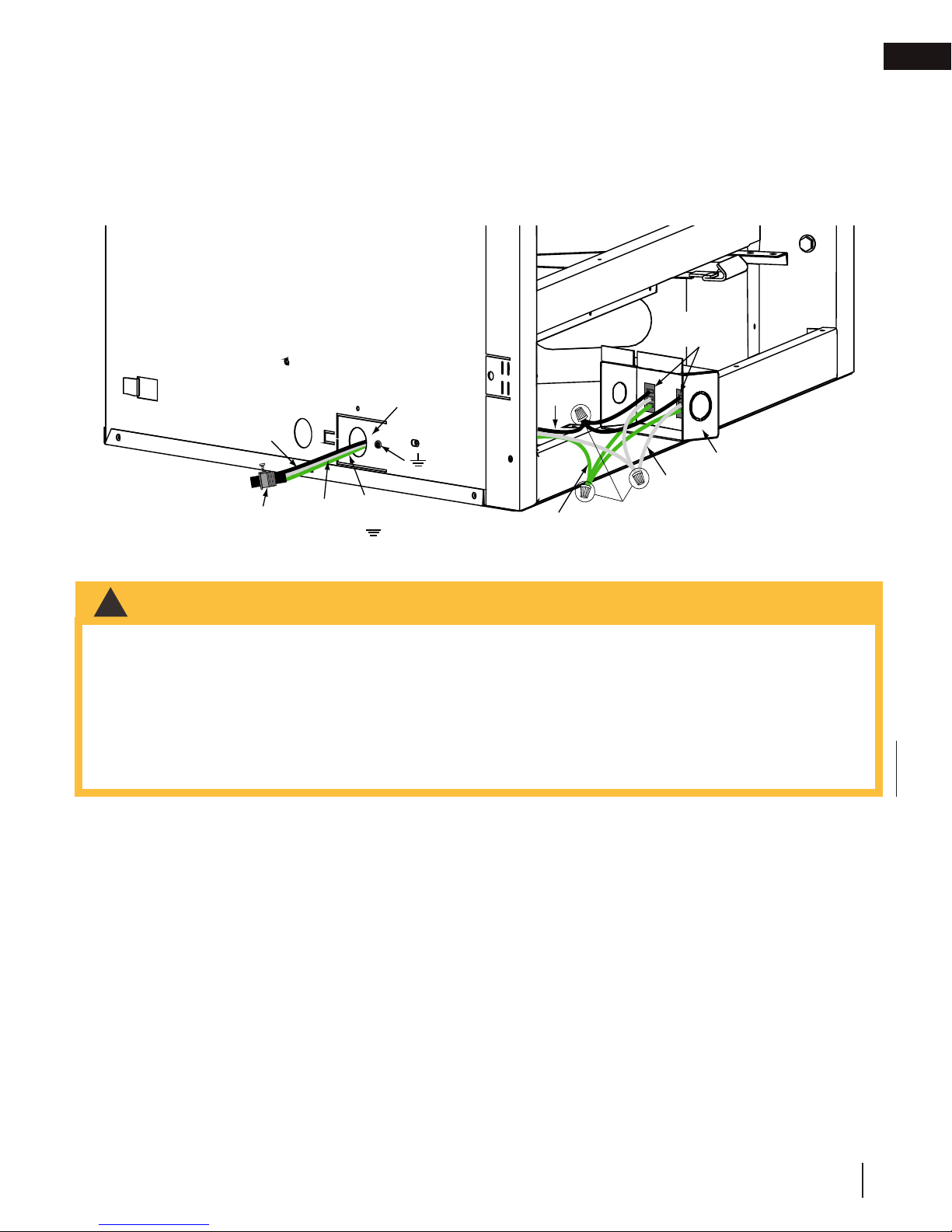
5.0 electrical information
!
WARNING
venting installation
5.1 hard wiring connection
It is necessary to hard wire this appliance.
This appliance must be electrically connected and grounded in accordance with local codes. In the absence of
local codes, use the current CSA C22.1 Canadian Electrical Code in Canada or the ANSI/NFPA 70-1996 National
Electrical Code in the United States.
5.2 receptacle wiring diagram
EN
5.3 electronic wiring diagram
• Do not use this appliance if any part has been under water. Call a qualifi ed service technician immediately to
have the appliance inspected for damage to the electrical circuit.
• Risk of electrical shock or explosion. Do not wire 110V to the valve or to the appliance wall switch. Incorrect
wiring will damage controls.
• All wiring should be done by a qualifi ed electrician and shall be in compliance with local codes. In the
absence of local codes, use the current CSA22.1 Canadian Electric Code in Canada or the current National
Electric Code ANSI/NFPA NO. 70 in the United States.
• Always light the pilot whether for the fi rst time or if the gas supply has run out, with the glass door opened or
removed.
W415-1793 / A / 05.07.18
23
EN
electrical information
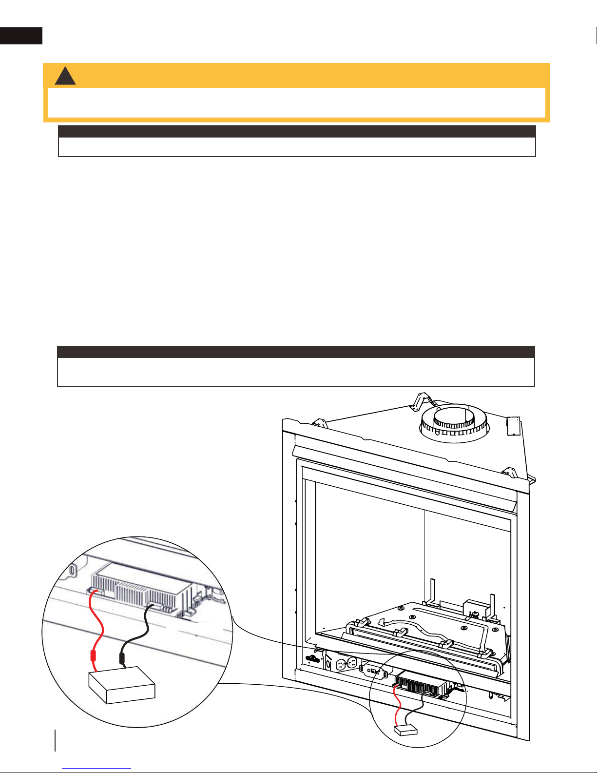
5.4 battery back-up installation
WARNING
!
• Ensure the gas and electrical power to the appliance is turned off.
• Appliance may be hot, do not service until the appliance has cooled.
note:
In the event of a power failure, your appliance can be operated using the supplied battery back-up.
A. Before beginning installation, turn off the gas and disconnect the electrical power supply from the
appliance.
B. Locate the battery housing supplied in the manual baggie.
C. Install 4 “AA” alkaline batteries (not supplied) into the battery housing, ensure the positive and negative
ends correspond with those identified on the holder. (To open the battery housing, slide the back piece
upwards and off of the battery housing).
D. Remove the safety screen to easily access the control compartment.
E. Attach the wire (on connector) labelled “BATTERY” from the wiring harness, located in the control
compartment of the appliance, to the battery housing.
F. Place the battery housing into the control compartment, ensure that the battery housing is placed in a
clean and easily accessible location.
G. Reinstall the safety screen. The safety screen must be installed at all times during the appliance operation.
H. Turn the gas and electrical power back on to begin operating the appliance.
note:
Once the power has been restored, remove the batteries from the holder. The system will drain the batteries if
they are left in the battery holder.
Red wire
Black wire
Battery housing
24
W415-1793 / A / 05.07.18
Control module
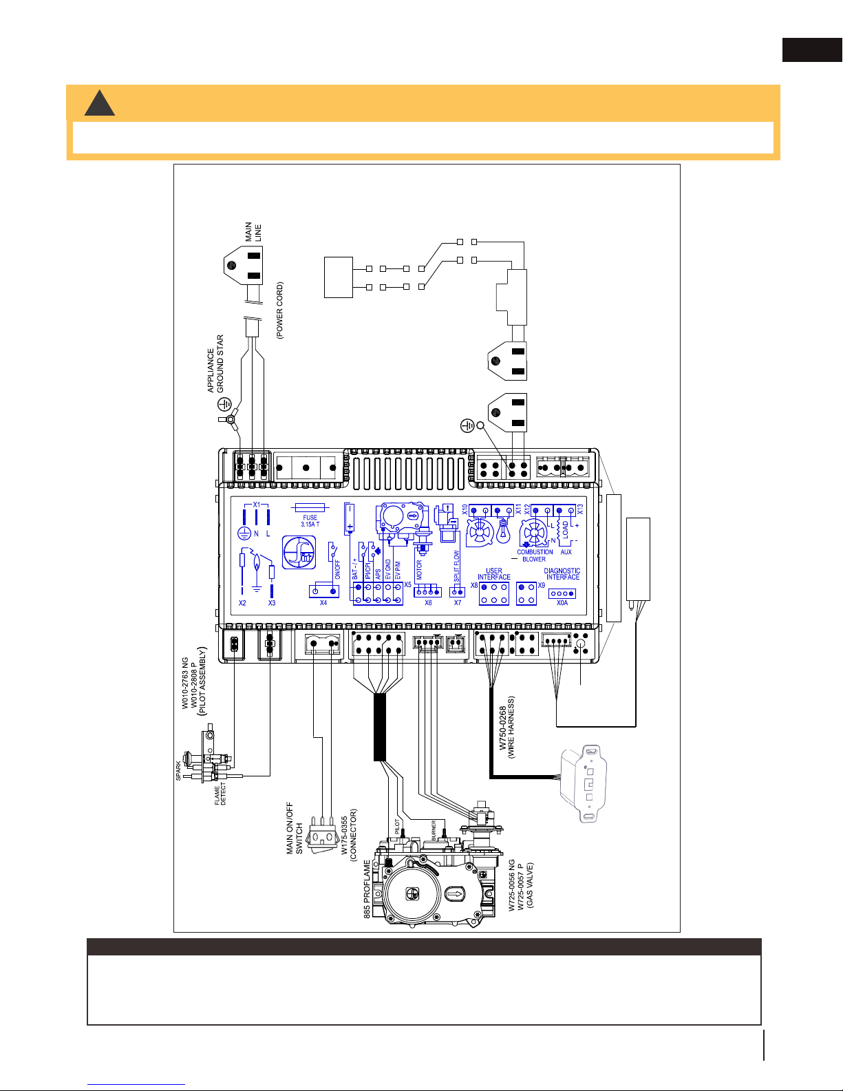
5.5 wiring diagram
WARNING
!
• Do not wire 110 volts to the valve or wall switch.
W405-0049
ACCENT LIGHTS
W750-0294
W750-0429
GROUND
electrical information
W707-0019
PIGTAIL)
W750-0358
(LIGHT/BLOWER/
EN
PILOT
W750-0276
WIRE HARNESS
COMFORT
FAN
W750-0317
LAMP
(EXTENSION)
(W190-0090)
BLUETOOTH
W190-0124 (RECEIVER)
RESET
BUTTON
W350-0655
WITH PROGRAM BUTTON
BATTERY HOLDER COMPLETE
note:
This appliance comes equipped with a battery back-up. If this back-up is used, install 4 ‘AA’ batteries (not
supplied) into the holder and connect to the wire harness. Connect the battery holder to the wire harness before
using the appliance. Place near the IPI board. If the back-up is used, it must be connected to this 6 volt battery
pack (supplied). Do not connect to a 9 volt battery pack.
W415-1793 / A / 05.07.18
25

EN
!
WARNING
• Check for gas leaks by brushing on a soap and water solution. Do not use open fl ame.
A. Nailing tabs are provided as part of the frames, as shown. To
* Additional fasteners may be installed.
1/2” FINISHING
MATERIAL
3/4” FINISHING
MATERIAL
6.0 gas installation
electrical information
• Risk of fi re, explosion, or asphyxiation. Ensure there are no ignition sources such as sparks or open fl ames.
• Support gas control when attaching gas supply pipe to prevent damaging gas line.
• Always light the pilot whether for the fi rst time or if the gas supply has run out with the glass door opened
or removed. Purging of the gas supply line should be performed by a qualifi ed service technician. Ensure
that a continuous gas fl ow is at the burner before closing the door. Ensure adequate ventilation. For gas and
electrical locations, see “dimensions” section.
• All gas connections must be contained within the appliance when complete (gas fi replaces only).
• High pressure will damage valve. Disconnect gas supply piping before testing gas line at test pressures above
1/2 PSIG.
• Valve settings have been factory set, do not change.
Installation and servicing to be done by a qualifi ed installer.
• Move the appliance into position and secure.
• If equipped with a fl ex connector, the appliance is designed to accept a 1/2” (13mm) gas supply. Without the
connector, it is designed to accept a 3/8” (9.5mm) gas supply. The appliance is equipped with a manual shut
off valve to turn off the gas supply to the appliance.
• Connect the gas supply in accordance to local codes. In the absence of local codes, install to the current
CAN/CSA-B149.1 Installation Code in Canada or to the current National Fuel Gas Code, ANSI Z223.1 / NFPA
54 in the United States.
• When fl exing any gas line, support the gas valve so that the lines are not bent or kinked.
• The gas line fl ex-connector should be installed to provide suffi cient movement for shifting the burner assembly
on its side to aid with servicing components.
After installing the electrical wiring and gas lines, ensure to test the appliance before finishing the framing and finishing the appliance.
7.0 nailing tab installation
determine the final location and where to bend the nailing tabs you
must first determine the thickness of your finishing material (i.e.
drywall). This will determine the dimension from the front edge of the
corner post to the nailing tab. Once the nailing tab is in the desired
location and secure using an appropriate fastener*.
ADD
NAILING
TABS
IMAGE
HERE
26
W415-1793 / A / 05.07.18

8.0 operation
!
WARNING
D.
• If you do not follow these instructions exactly, a fi re or explosion may result causing property damage, personal
injury, or loss of life.
• If applicable, always light the pilot whether for the fi rst time or if the gas supply has run out with the glass door
opened or removed.
Ensure that a continuous gas fl ow is at the burner before installing the door. When lit for the fi rst time, the
appliance will emit an odor for a few hours. This is a normal temporary condition caused by the “burn-in” of
paints and lubricants used in the manufacturing process and will not occur again. After extended periods of
non-operation, such as, following a vacation or warm weather season, the appliance may emit a slight odor for a
few hours. This is caused by dust particules in the heat exchanger burning off. In both cases, open a window to
suffi ciently ventilate the room.
FOR YOUR SAFETY READ BEFORE LIGHTING
• Do not turn on if children or other at risk individuals are near the appliance.
• This appliance is equipped with an ignition device which automatically lights the pilot. Do not try to light the
pilot by hand.
• Before operating, smell all around the appliance area for gas and next to the fl oor because some gas is
heavier than air and will settle on the fl oor.
• Do not use this appliance if any part has been under water. Immediately call a qualifi ed service technician
to inspect the appliance and replace any part of the control system and any gas control which has been
underwater.
WHAT TO DO IF YOU SMELL GAS
• Turn off all gas to the appliance.
• Open windows.
• Do not try to light any appliance.
• Do not touch any electric switch; do not use
any phone in your building
• Immediately call your gas supplier from a
neighbour’s phone. Follow the gas supplier’s
instructions.
• If you cannot reach your gas supplier, call
the fi re department.
operation
EN
LIGHTING INSTRUCTIONS
note:
This appliance is equipped with an ignition device which automatically lights the pilot. Do not try to light the
pilot by hand.
A. Stop! Read the above safety information on this label.
B. Remove batteries from the transmitter and set thermostat to lowest setting, if
equipped.
C. Turn off all electrical power to the appliance.
D. Open the glass door, if equipped.
E. Turn the manual shut-off valve clockwise to the “OFF” position. (Shut-off valve is
located on the fl ex connector).
F. Wait fi ve (5) minutes to clear out any gas. If you smell gas including near the
fl oor, STOP! Follow the instructions above in the “WHAT TO DO IF YOU
SMELL GAS” section. If you don’t smell gas; close the glass door and go to
the next step.
G. Turn the manual shut-off valve counter clockwise to the “ON” position.
H. Turn on all electrical power to the appliance and re-install the batteries into the
transmitter. Set thermostat to desired setting, if equipped.
I. Turn on the remote wall switch to the appliance.
J. If the appliance will not operate, follow instructions “TO TURN OFF GAS” and
call your service technician or gas supplier.
TO TURN OFF GAS
A. Set thermostat to lowest setting, if equipped.
B. Turn off the remote wall switch to the appliance.
C. Turn off all electric power to the appliance if service is to be performed.
Turn manual shutoff valve clockwise to the “OFF” positon. Do not force.
add gas knob
O
MANUAL SHUT-OFF
(SHOWN IN OFF POSITION)
add gas valve
S
W415-1793 / A / 05.07.18
27
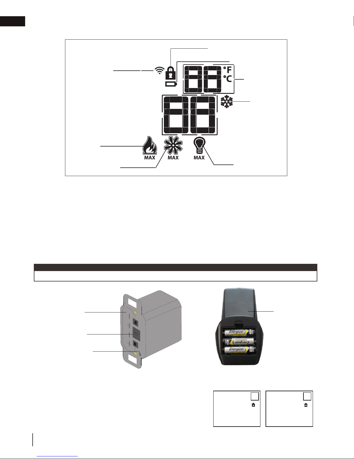
EN
A. Press the on / off key on the transmitter. The transmitter display will
show all active icons on the screen. A single “beep” from the receiver will
confi rm reception of the command.
Blue LCD Display
On / Off Key
Up / Down Arrow Key
Mode Key
Temperature Key
76
°F
OFF
76
°F
ON
°F
ADD TITLE: TEMPERATURE DISPLAY
A. With the system in the off position, press the temperature key
ADD TITLE: HAND HELD REMOTE OPERATION
Blue LCD Display
On / Off Key
Up / Down Arrow Key
Mode Key
Temperature Key
73 23
76
°F
68
Room Temperature
Set Temperature
°F
76
°F
OFF
76
°F
ON
76
°F
76
°F
68
76
°F
Hi
76
°F
76
°F
ON
°F °C
Blue LCD Display
On / Off Key
Up / Down Arrow Key
Mode Key
Temperature Key
73 23
76
°F
OFF
76
°F
ON
76
°F
°F °C
Blue LCD Display
On / Off Key
Up / Down Arrow Key
Mode Key
Temperature Key
73 23
76
°F
OFF
76
°F
ON
76
°F
°F
°F
°F °C
Blue LCD Display
On / Off Key
Up / Down Arrow Key
Mode Key
Temperature Key
73 23
76
°F
OFF
76
°F
ON
76
°F
Blue LCD Display
On / Off Key
Up / Down Arrow Key
Mode Key
Temperature Key
73 23
76
°F
OFF
76
°F
ON
76
°F
°F
°F
°F °C
operation
8.1 general transmitter layout
Transmission
Flame ON
Key Lock
Low battery alarm
Room
Temperature
CPI mode
Blower
8.2 initializing the transmitter / battery holder for the first time
A. Install the 4 AA batteries into the Proflame 2 battery holder, note the polarity of the batteries and insert as
indicated on the cover (+/-).
B. Ensure the 3 position slider switch is switched to the “REMOTE” position (middle position).
C. Press the reset/programming button, use a small object such as a paper clip in order to reach the button
marked PRG, as shown in the illustration below.
D. The battery holder will beep 3 times to indicate that it’s ready to synchronize with the transmitter.
E. Install the 3 AAA batteries into the transmitter, as shown in the photograph below, then press the ON
button, The battery holder will beep 4 times to indicate that the transmitter’s command is accepted.
note:
The initializing process must be completed within 10 seconds of pressing the reset/program button (PRG).
BATTERY HOLDER
SLIDER SWITCH
28
RESET/PROGRAM
BUTTON (PRG)
8.3 temperature display
and the mode key at the same time to change from degrees F to
C.
B. Look at the LCD screen on the transmitter to verify that a C or F is
visible to the right of the room temperature display.
W415-1793 / A / 05.07.18
(4) AA Batteries
Light
TRANSMITTER
°F °C
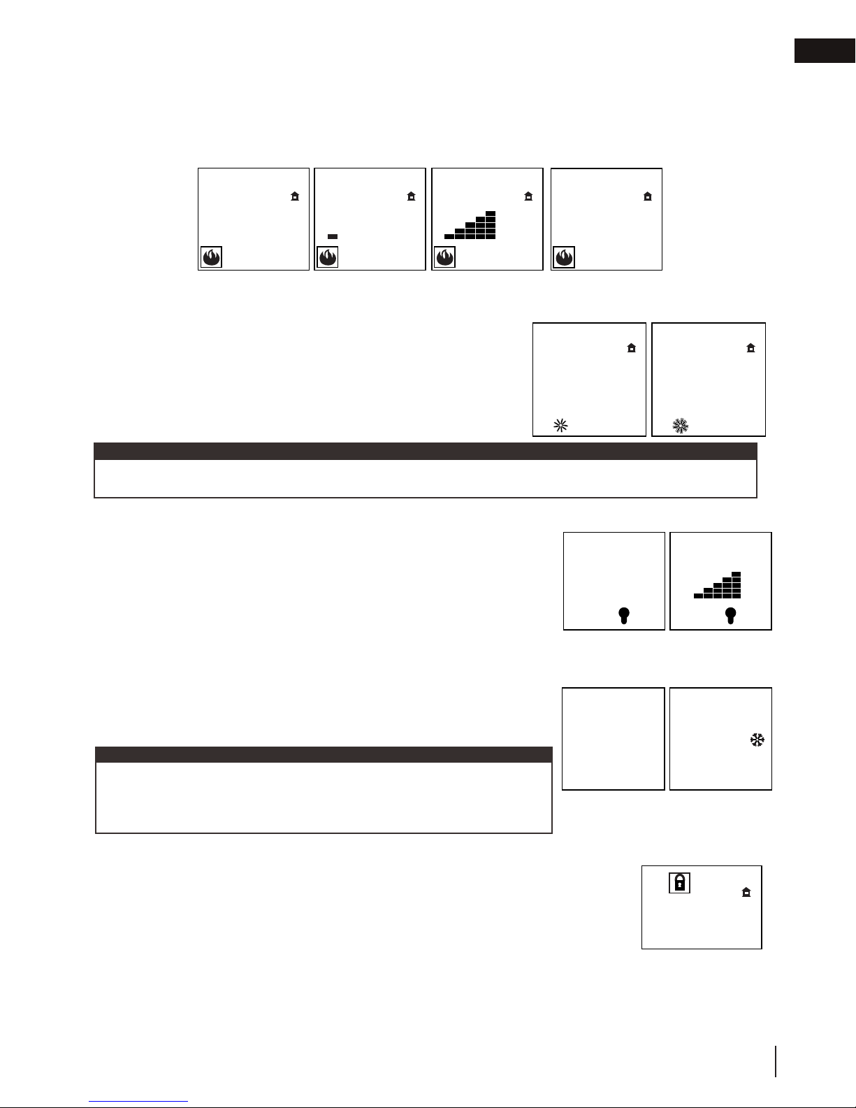
A. Press the on / off key on the transmitter. The transmitter display will
show all active icons on the screen. A single “beep” from the receiver will
confi rm reception of the command.
Blue LCD Display
On / Off Key
Up / Down Arrow Key
Mode Key
Temperature Key
76
°F
OFF
76
°F
ON
°F
ADD TITLE: TEMPERATURE DISPLAY
A. With the system in the off position, press the temperature key
and the mode key at the same time to change from degrees F to
C.
B. Look at the LCD screen on the transmitter to verify that a C or F is
visible to the right of the room temperature display.
ADD TITLE: HAND HELD REMOTE OPERATION
The remote control has six (6) fl ame levels. With the system on and the fl ame level at the maximum, press the
down arrow key once and it will reduce the fl ame height by one step until the fl ame is turned off.
The up arrow key will increase the fl ame height each time it is pressed. If the up arrow key is pressed while
the system is on but the fl ame is off, the fl ame will come on at the high position. A single “beep” will confi rm
reception of the command.
ADD TITLE: FLAME HEIGHT
Blue LCD Display
On / Off Key
Up / Down Arrow Key
Mode Key
Temperature Key
73 23
76
°F
68
Room Temperature
Set Temperature
76
°F
MAX
76
°F
OFF
76
°F
76
°F
76
°F
Hi
Flame Off Flame at level 1 Flame at level 5 Flame at “Hi” level 6
76
°F
OFF
76
°F
ON
76
°F
76
°F
68
76
°F
Hi
76
°F
OFF
76
°F
ON
SMART
°F °C
If the appliance is equipped with a hot air circulating fan, the speed of
ADD TITLE: FAN SPEED
76
°F
OFF
76
°F
ON
76
°F
76
76
Blue LCD Display
On / Off Key
Up / Down Arrow Key
Mode Key
Temperature Key
73 23
76
°F
68
Room Temperature
76
°F
MAX
76
°F
OFF
76
°F
76
°F
76
°F
Hi
Flame Off Flame at level 1 Flame at level 5 Flame at “Hi” level 6
76
°F
OFF
76
°F
ON
76
°F
76
°F
68
76
°F
Hi
76
°F
OFF
76
°F
ON
SMART
°F °C
Blue LCD Display
On / Off Key
Up / Down Arrow Key
Mode Key
Temperature Key
73 23
76
°F
68
Room Temperature
76
°F
MAX
76
°F
OFF
76
°F
76
°F
76
°F
Hi
Flame Off Flame at level 1 Flame at level 5 Flame at “Hi” level 6
76
°F
OFF
76
°F
ON
76
°F
76
°F
68
76
°F
Hi
76
°F
OFF
76
°F
ON
SMART
°F °C
Blue LCD Display
On / Off Key
Up / Down Arrow Key
Mode Key
Temperature Key
73 23
76
°F
OFF
76
°F
ON
76
°F
°F °C
Blue LCD Display
On / Off Key
Up / Down Arrow Key
Mode Key
Temperature Key
73 23
76
°F
OFF
76
°F
ON
76
°F
°F
°F
°F °C
76
°F
OFF
76
°F
ON
°F
A. Press the on / off key on the transmitter. The transmitter display will
show all active icons on the screen. A single “beep” from the receiver will
confi rm reception of the command.
Blue LCD Display
On / Off Key
Up / Down Arrow Key
Mode Key
Temperature Key
76
°F
OFF
76
°F
ON
°F
ADD TITLE: TEMPERATURE DISPLAY
A. With the system in the off position, press the temperature key
and the mode key at the same time to change from degrees F to
C.
B. Look at the LCD screen on the transmitter to verify that a C or F is
visible to the right of the room temperature display.
ADD TITLE: HAND HELD REMOTE OPERATION
The remote control has six (6) fl ame levels. With the system on and the fl ame level at the maximum, press the
ADD TITLE: FLAME HEIGHT
Blue LCD Display
On / Off Key
Up / Down Arrow Key
Mode Key
Temperature Key
73 23
76
°F
68
Room Temperature
Set Temperature
76
°F
MAX
76
76
76
76
76
°F
OFF
76
°F
ON
76
°F
76
°F
68
76
°F
Hi
76
°F
OFF
76
°F
ON
SMART
°F °C
76
°F
OFF
76
°F
ON
76
°F
Blue LCD Display
On / Off Key
Up / Down Arrow Key
Mode Key
Temperature Key
73 23
76
°F
68
Room Temperature
76
°F
76
°F
OFF
76
°F
ON
76
°F
76
°F
68
76
°F
Hi
76
°F
OFF
76
°F
ON
SMART
°F °C
Blue LCD Display
On / Off Key
Up / Down Arrow Key
Mode Key
Temperature Key
73 23
76
°F
68
Room Temperature
76
°F
76
°F
OFF
76
°F
ON
76
°F
76
°F
68
76
°F
Hi
76
°F
OFF
76
°F
ON
SMART
°F °C
Blue LCD Display
On / Off Key
Up / Down Arrow Key
Mode Key
Temperature Key
73 23
76
°F
OFF
76
°F
ON
76
°F
°F °C
Blue LCD Display
On / Off Key
Up / Down Arrow Key
Mode Key
Temperature Key
73 23
76
°F
OFF
76
°F
ON
76
°F
°F
°F
°F °C
Blue LCD Display
On / Off Key
Up / Down Arrow Key
Mode Key
Temperature Key
76
°F
OFF
76
°F
ON
°F
ADD TITLE: TEMPERATURE DISPLAY
A. With the system in the off position, press the temperature key
and the mode key at the same time to change from degrees F to
C.
B. Look at the LCD screen on the transmitter to verify that a C or F is
visible to the right of the room temperature display.
The remote control has six (6) fl ame levels. With the system on and the fl ame level at the maximum, press the
down arrow key once and it will reduce the fl ame height by one step until the fl ame is turned off.
The up arrow key will increase the fl ame height each time it is pressed. If the up arrow key is pressed while
the system is on but the fl ame is off, the fl ame will come on at the high position. A single “beep” will confi rm
reception of the command.
ADD TITLE: FLAME HEIGHT
Blue LCD Display
On / Off Key
Up / Down Arrow Key
Mode Key
Temperature Key
73 23
76
°F
68
Room Temperature
Set Temperature
76
°F
MAX
76
°F
OFF
76
°F
76
°F
76
°F
Hi
Flame Off Flame at level 1 Flame at level 5 Flame at “Hi” level 6
76
°F
OFF
76
°F
ON
76
°F
76
°F
68
76
°F
Hi
76
°F
OFF
76
°F
ON
SMART
°F °C
If the appliance is equipped with a hot air circulating fan, the speed of
the fan can be controlled by the remote system. The fan speed can be
adjusted through six (6) speeds.
A. Use the mode key to guide you to the fan control icon.
B. Use the up/down arrow keys to turn on/off or adjust the fan
speed. A single “beep” will confi rm reception of the command.
ADD TITLE: FAN SPEED
76
°F
OFF
76
°F
ON
76
°F
76
°F
68
76
°F
Hi
ADD TITLE: CHILD PROOF FUNCTION
This function will lock the keys to avoid unsupervised operation.
A. Press the mode and up keys at the same time.
B. To de-activate this function, press the mode and up keys at the same time.
Blue LCD Display
On / Off Key
Up / Down Arrow Key
Mode Key
Temperature Key
73 23
76
°F
68
Room Temperature
76
°F
MAX
76
°F
OFF
76
°F
76
°F
76
°F
Hi
Flame Off Flame at level 1 Flame at level 5 Flame at “Hi” level 6
76
°F
76
°F
OFF
76
°F
ON
76
°F
76
°F
68
76
°F
Hi
76
°F
OFF
76
°F
76
°F
IPI
76
°F
CPI
ON
SMART
°F °C
Blue LCD Display
On / Off Key
Up / Down Arrow Key
Mode Key
Temperature Key
73 23
76
°F
OFF
76
°F
ON
76
°F
°F °C
Blue LCD Display
On / Off Key
Up / Down Arrow Key
Mode Key
Temperature Key
73 23
76
°F
OFF
76
°F
ON
76
°F
°F
°F
°F °C
When the desired blower speed is selected, the blower will automatically come on 5 minutes after the main
burner has been turned on and remain on twelve minutes after it has been turned off.
note:
ADD TITLE: NIGHT LIGHT
The auxiliary function controls the AUX power outlet on the control module
which controls the Night Light™.
A. Use the mode key to guide you to the AUX icon.
B. Pressing the up arrow key will activate the Night Light™.
C. Pressing the down arrow key will turn the Night Light™ off. A single
“beep” will confi rm the reception of the command.
76
°F
OFF
76
°F
ON
ADD TITLE: Night Light Dimmer Control
76
°F
OFF
76
°F
ON
76
°F
76
°F
68
76
°F
Hi
76
76
will confi rm reception of the command.
76
°F
76
°F
Hi
76
°F
OFF
76
°F
ON
76
°F
76
°F
68
76
°F
Hi
76
°F
OFF
76
°F
Blue LCD Display
On / Off Key
Up / Down Arrow Key
Mode Key
Temperature Key
76
°F
OFF
76
°F
ON
°F
visible to the right of the room temperature display.
The remote control has six (6) fl ame levels. With the system on and the fl ame level at the maximum, press the
down arrow key once and it will reduce the fl ame height by one step until the fl ame is turned off.
The up arrow key will increase the fl ame height each time it is pressed. If the up arrow key is pressed while
the system is on but the fl ame is off, the fl ame will come on at the high position. A single “beep” will confi rm
reception of the command.
ADD TITLE: FLAME HEIGHT
Blue LCD Display
On / Off Key
Up / Down Arrow Key
Mode Key
Temperature Key
73 23
76
°F
68
Room Temperature
Set Temperature
76
°F
MAX
76
°F
OFF
76
°F
76
°F
76
°F
Hi
Flame Off Flame at level 1 Flame at level 5 Flame at “Hi” level 6
76
°F
OFF
76
°F
ON
76
°F
76
°F
68
76
°F
Hi
76
°F
OFF
76
°F
ON
SMART
°F °C
If the appliance is equipped with a hot air circulating fan, the speed of
the fan can be controlled by the remote system. The fan speed can be
adjusted through six (6) speeds.
A. Use the mode key to guide you to the fan control icon.
B. Use the up/down arrow keys to turn on/off or adjust the fan
speed. A single “beep” will confi rm reception of the command.
ADD TITLE: FAN SPEED
76
°F
OFF
76
°F
ON
76
°F
76
°F
68
76
°F
Hi
ADD TITLE: CHILD PROOF FUNCTION
This function will lock the keys to avoid unsupervised operation.
A. Press the mode and up keys at the same time.
B. To de-activate this function, press the mode and up keys at the same time.
Blue LCD Display
On / Off Key
Up / Down Arrow Key
Mode Key
Temperature Key
73 23
76
°F
68
Room Temperature
76
°F
MAX
76
°F
OFF
76
°F
76
°F
76
°F
Hi
Flame Off Flame at level 1 Flame at level 5 Flame at “Hi” level 6
76
°F
76
°F
OFF
76
°F
ON
76
°F
76
°F
68
76
°F
Hi
76
°F
OFF
76
°F
76
°F
IPI
76
°F
CPI
ON
SMART
°F °C
Blue LCD Display
On / Off Key
Up / Down Arrow Key
Mode Key
Temperature Key
73 23
76
°F
68
Room Temperature
76
°F
MAX
76
°F
OFF
76
°F
76
°F
76
°F
Hi
Flame Off Flame at level 1 Flame at level 5 Flame at “Hi” level 6
76
°F
76
°F
OFF
76
°F
ON
76
°F
76
°F
68
76
°F
Hi
76
°F
OFF
76
°F
76
°F
IPI
76
°F
CPI
ON
SMART
°F °C
Blue LCD Display
On / Off Key
Up / Down Arrow Key
Mode Key
Temperature Key
73 23
76
°F
OFF
76
°F
ON
76
°F
°F °C
Blue LCD Display
On / Off Key
Up / Down Arrow Key
Mode Key
Temperature Key
73 23
76
°F
OFF
76
°F
ON
76
°F
°F
°F
°F °C
When the desired blower speed is selected, the blower will automatically come on 5 minutes after the main
burner has been turned on and remain on twelve minutes after it has been turned off.
note:
ADD TITLE: NIGHT LIGHT
The auxiliary function controls the AUX power outlet on the control module
which controls the Night Light™.
A. Use the mode key to guide you to the AUX icon.
B. Pressing the up arrow key will activate the Night Light™.
C. Pressing the down arrow key will turn the Night Light™ off. A single
“beep” will confi rm the reception of the command.
76
°F
OFF
76
°F
ON
ADD TITLE: Night Light Dimmer Control
76
°F
OFF
76
°F
ON
76
°F
76
°F
68
76
°F
Hi
76
°F
OFF
76
°F
The auxiliary function controls the Night Light™ with dimmable control.
A. Use the mode key to guide you to the Night Light™ icon.
B. The intensity of the output can be adjusted through 6 levels.
Use the up/down arrow keys to adjust the output level. A single beep
will confi rm reception of the command.
ADD TITLE: CONTINUOUS PILOT / INTERMITTENT PILOT (CPI / IPI) SELECTION
A. When the transmitter is in the off position, use the mode key to guide
76
°F
76
°F
ON
76
°F
76
°F
ON
76
°F
76
°F
Hi
76
°F
OFF
76
°F
ON
76
°F
76
°F
68
76
°F
Hi
76
°F
OFF
76
°F
76
76
A. Press the on / off key on the transmitter. The transmitter display will
show all active icons on the screen. A single “beep” from the receiver will
confi rm reception of the command.
Blue LCD Display
On / Off Key
Up / Down Arrow Key
Mode Key
Temperature Key
76
°F
OFF
76
°F
ON
°F
ADD TITLE: TEMPERATURE DISPLAY
A. With the system in the off position, press the temperature key
and the mode key at the same time to change from degrees F to
C.
B. Look at the LCD screen on the transmitter to verify that a C or F is
visible to the right of the room temperature display.
ADD TITLE: HAND HELD REMOTE OPERATION
The remote control has six (6) fl ame levels. With the system on and the fl ame level at the maximum, press the
down arrow key once and it will reduce the fl ame height by one step until the fl ame is turned off.
The up arrow key will increase the fl ame height each time it is pressed. If the up arrow key is pressed while
the system is on but the fl ame is off, the fl ame will come on at the high position. A single “beep” will confi rm
reception of the command.
ADD TITLE: FLAME HEIGHT
Blue LCD Display
On / Off Key
Up / Down Arrow Key
Mode Key
Temperature Key
73 23
76
°F
68
Room Temperature
Set Temperature
76
°F
MAX
76
°F
OFF
76
°F
76
°F
76
°F
Hi
Flame Off Flame at level 1 Flame at level 5 Flame at “Hi” level 6
76
°F
OFF
76
°F
ON
76
°F
76
°F
68
76
°F
Hi
76
°F
OFF
76
°F
ON
SMART
°F °C
If the appliance is equipped with a hot air circulating fan, the speed of
the fan can be controlled by the remote system. The fan speed can be
adjusted through six (6) speeds.
A. Use the mode key to guide you to the fan control icon.
B. Use the up/down arrow keys to turn on/off or adjust the fan
speed. A single “beep” will confi rm reception of the command.
ADD TITLE: FAN SPEED
76
°F
OFF
76
°F
ON
76
°F
76
°F
68
76
°F
Hi
ADD TITLE: CHILD PROOF FUNCTION
Blue LCD Display
On / Off Key
Up / Down Arrow Key
Mode Key
Temperature Key
73 23
76
°F
68
Room Temperature
76
°F
MAX
76
°F
OFF
76
°F
76
°F
76
°F
Hi
Flame Off Flame at level 1 Flame at level 5 Flame at “Hi” level 6
76
76
°F
OFF
76
°F
ON
76
°F
76
°F
68
76
°F
Hi
76
°F
OFF
76
°F
76
°F
IPI
76
°F
CPI
ON
SMART
°F °C
Blue LCD Display
On / Off Key
Up / Down Arrow Key
Mode Key
Temperature Key
73 23
76
°F
68
Room Temperature
76
°F
MAX
76
°F
OFF
76
°F
76
°F
76
°F
Hi
Flame Off Flame at level 1 Flame at level 5 Flame at “Hi” level 6
76
°F
76
°F
OFF
76
°F
ON
76
°F
76
°F
68
76
°F
Hi
76
°F
OFF
76
°F
76
°F
IPI
76
°F
CPI
ON
SMART
°F °C
Blue LCD Display
On / Off Key
Up / Down Arrow Key
Mode Key
Temperature Key
73 23
76
°F
OFF
76
°F
ON
76
°F
°F °C
Blue LCD Display
On / Off Key
Up / Down Arrow Key
Mode Key
Temperature Key
73 23
76
°F
OFF
76
°F
ON
76
°F
°F
°F
°F °C
When the desired blower speed is selected, the blower will automatically come on 5 minutes after the main
burner has been turned on and remain on twelve minutes after it has been turned off.
note:
76
°F
OFF
76
°F
ON
76
°F
OFF
76
°F
ON
76
°F
°F
°F
8.4 flame height
down arrow key once and it will reduce the fl ame height by one step until the fl ame is turned off.
The up arrow key will increase the fl ame height each time it is pressed. If the up arrow key is pressed while
the system is on but the fl ame is off, the fl ame will come on at the high position. A single “beep” will confi rm
reception of the command.
°F
°F
°F
OFF
8.5 blower speed
the fan can be controlled by the remote system. The fan speed can be
adjusted through six (6) speeds.
A. Use the mode key to guide you to the fan control icon.
B. Use the up/down arrow keys to turn on/off or adjust the fan
speed. A single “beep” will confi rm reception of the command.
note:
When the desired blower speed is selected, the blower will automatically come on 5 minutes after the main
burner has been turned on and remain on twelve minutes after it has been turned off.
8.6 night light dimmer control
The auxiliary function controls the Night Light™ with dimmable control.
A. Use the mode key to guide you to the Night Light™ icon.
B. The intensity of the output can be adjusted through 6 levels.
8.7 continuous pilot / intermittent pilot (CPI / IPI) selection
B. Press the up/down to switch between IPI and CPI modes. A single
note:
If the appliance is equipped with a CPI/IPI toggle switch, set the CPI/IPI
to CPI position to enable remote CPI operation. If the switch is set to IPI
then it will only work in IPI regardless of what is set on the remote control
handset.
8.8 key lock
This function will lock the keys to avoid unsupervised operation.
A. Press the mode and up keys at the same time.
B. To de-activate this function, press the mode and up keys at the same time.
Use the up/down arrow keys to adjust the output level. A single beep
you to the CPI mode icon.
beep will confi rm reception of the command.
Flame Off Flame at level 1 Flame at level 5 Flame at “Hi” level 6
Hi
°F
68
OFF
IPI
operation
°F
Hi
°F
°F
CPI
W415-1793 / A / 05.07.18
EN
°F
°F
°F
°F
29
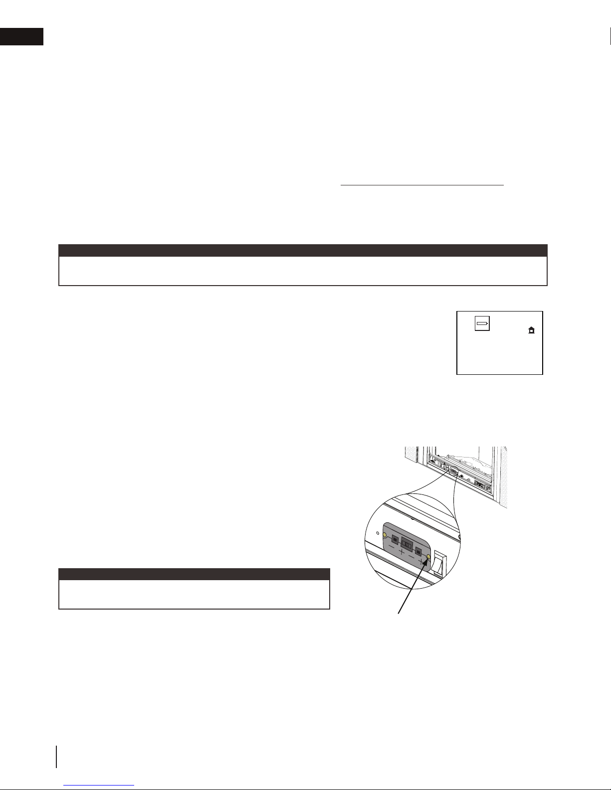
EN
Blue LCD Display
On / Off Key
Up / Down Arrow Key
Mode Key
Temperature Key
76
°F
OFF
76
°F
ON
°F
Blue LCD Display
On / Off Key
Up / Down Arrow Key
Mode Key
Temperature Key
73 23
76
°F
68
Room Temperature
Set Temperature
76
°F
MAX
76
°F
OFF
76
°F
76
°F
76
°F
Hi
Flame Off Flame at level 1 Flame at level 5 Flame at “Hi” level 6
76
°F
OFF
76
°F
ON
76
°F
76
°F
68
76
°F
Hi
76
°F
OFF
76
°F
ON
SMART
°F °C
If the appliance is equipped with a hot air circulating fan, the speed of
the fan can be controlled by the remote system. The fan speed can be
adjusted through six (6) speeds.
A. Use the mode key to guide you to the fan control icon.
B. Use the up/down arrow keys to turn on/off or adjust the fan
speed. A single “beep” will confi rm reception of the command.
ADD TITLE: FAN SPEED
76
°F
OFF
76
°F
ON
76
°F
76
°F
68
76
°F
Hi
ADD TITLE: CHILD PROOF FUNCTION
This function will lock the keys to avoid unsupervised operation.
A. Press the mode and up keys at the same time.
B. To de-activate this function, press the mode and up keys at the same time.
Blue LCD Display
On / Off Key
Up / Down Arrow Key
Mode Key
Temperature Key
73 23
76
°F
68
Room Temperature
76
°F
MAX
76
°F
OFF
76
°F
76
°F
76
°F
Hi
Flame Off Flame at level 1 Flame at level 5 Flame at “Hi” level 6
76
°F
76
°F
OFF
76
°F
ON
76
°F
76
°F
68
76
°F
Hi
76
°F
OFF
76
°F
76
°F
IPI
76
°F
CPI
ON
SMART
°F °C
Blue LCD Display
On / Off Key
Up / Down Arrow Key
Mode Key
Temperature Key
73 23
76
°F
OFF
76
°F
ON
76
°F
°F °C
Blue LCD Display
On / Off Key
Up / Down Arrow Key
Mode Key
Temperature Key
73 23
76
°F
OFF
76
°F
ON
76
°F
°F
°F
°F °C
When the desired blower speed is selected, the blower will automatically come on 5 minutes after the main
burner has been turned on and remain on twelve minutes after it has been turned off.
note:
ADD TITLE: NIGHT LIGHT
The auxiliary function controls the AUX power outlet on the control module
which controls the Night Light™.
A. Use the mode key to guide you to the AUX icon.
B. Pressing the up arrow key will activate the Night Light™.
C. Pressing the down arrow key will turn the Night Light™ off. A single
“beep” will confi rm the reception of the command.
76
°F
OFF
76
°F
ON
The life span of the remote batteries depends on various factors: quality of the batteries,
ADD TITLE: LOW BATTERY / MANUAL BYPASS
ADD TITLE: Night Light Dimmer Control
76
°F
OFF
76
°F
ON
76
°F
76
°F
68
76
°F
Hi
76
°F
OFF
76
°F
The auxiliary function controls the Night Light™ with dimmable control.
A. Use the mode key to guide you to the Night Light™ icon.
B. The intensity of the output can be adjusted through 6 levels.
Use the up/down arrow keys to adjust the output level. A single beep
will confi rm reception of the command.
ADD TITLE: CONTINUOUS PILOT / INTERMITTENT PILOT (CPI / IPI) SELECTION
A. When the transmitter is in the off position, use the mode key to guide
you to the CPI mode icon.
B. Press the up/down to switch between IPI and CPI modes. A single
beep will confi rm reception of the command.
76
°F
76
°F
ON
76
76
°F
76
°F
ON
76
°F
76
°F
76
°F
Hi
76
°F
OFF
76
°F
ON
76
°F
76
°F
68
76
°F
Hi
76
°F
OFF
76
°F
76
°F
IPI
76
°F
CPI
If the appliance is equipped with a CPI/IPI toggle switch, set the CPI/IPI
to CPI position to enable remote CPI operation. If the switch is set to IPI
then it will only work in IPI regardless of what is set on the remote control
handset.
note:
operation
8.9 eFIRE Controller application
Napoleon’s eFIRE application will revolutionize the way you use your fireplace! We have cracked the code and
present to you the first fireplace to be controlled by Bluetooth technology, using an intuitive app on your mobile
device.
When fully equipped (if applicable), the eFIRE application allows you to select from a multitude of colours to suit
30
your mood or décor simply by scrolling through the colour wheel. Additionally, Napoleon’s eFIRE application allows
you to control many other functions of your fireplace, including on/off, flame height, light feature, blower, and a
timer to create a schedule for your fireplace that works for you.
Using the instructions on the eFIRE Controller application website http://napoleonfireplace.com/efire, install
the application and enjoy the features the eFIRE Controller application has to offer. *
* Visit the website or contact your authorized dealer for appliance-specific information and/or frequently asked
questions regarding features and products available with the eFIRE Controller application.
note:
The remote control is considered the master control for the appliance and can always be used to turn the
appliance off (ex. the eFIRE Controller application user, in control of the appliance, leaves the home).
8.10 low battery
the number of ignitions, etc.
When the transmitter batteries are low, a battery icon will appear on the LCD display
before all battery power is lost. When the batteries are replaced, this icon will disappear.
When the receiver batteries are low, no “beep” will be emitted from the receiver when
it receives an on/off command. This in an alert for the receiver that there’s low battery.
When the batteries are replaced the “beep” will be emitted from the receiver when the on/off key is pressed.
If the batteries of the receiver or transmitter are low, the appliance can be turned on manually by sliding the
three position slider switch on the receiver to the on position. This will bypass the remote control feature and the
appliance main burner will come on if the gas valve is in the on position.
8.11 battery holder / backup installation
A. The battery holder is located in the valve compartment,
accessible for programming the remote.
B. Install 4 AA batteries, Ensure that the positive and negative
ends correspond with those identified in the battery holder.
C. In the case of a power outage, the 3 position slider switch
needs to be in the “ON” position (left).
note:
Ensure the 3 positions slider switch is in the “REMOTE”
position (middle).
W415-1793 / A / 05.07.18
(4) AA Batteries
RESET/PROGRAM BUTTON (PRG)
°F
(4) AA Batteries
 Loading...