

Page 1
XP-400 Programming Instructions
®
Note: These Programming Instruction are intended to be used in conjunction with WI854C,
please refer to WI854C for additional information, instructions and definitions.
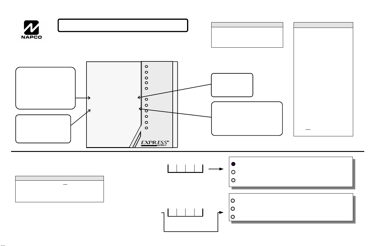
DEALER PROGRAM MODE - KEYPAD KEY DEFINITION
Hexadecimal Data Entry
To Enter a hexadecimal digit
enter the following:
A= A1 D= A4
B= A2 E= A5
C= A3 F= A6
Scroll Key
Use this key to scroll
through data that has been
entered in Programming
Blocks.
1 2 3
4 5 6
7 8 9
A 0 B
C D
K F G
K F G
ARMED
READY
FIRE
AC
ZONE 1
ZONE 2
ZONE 3
ZONE 4
ZONE 5
ZONE 6
NAPCO
NOTE:
After 15 minutes of keypad inactivity the keypad
will emit a steady tone indicating the panel has been
left in Dealer Program Mode. Enter Dealer Code to
exit or press the B key to return to Dealer
SYSTEMjj
Set Key
Press this key before
entering a Programming Block Number.
Blank Key
Press this key to disable all features within a LED type Programming Block or to blank out digits in
a Direct Entry type Programming
Block.
DEFAULTING THE PANEL
1. Remove power from the panel.
2. Remove all wiring from terminal
15 (PGM) and terminal 3.
3. Connect terminal 15 (PGM) to
terminal 3.
4. Apply power to the XP-400 control panel.
5. After a few seconds the ARMED,
READY and jSYSTEM TROU-
BLE LEDs will flash.
6. The keypad will beep 3 times
indicating the panel default values have been loaded.
7. Remove wiring between terminal
15 (PGM) and terminal 3.
8. Re-install original wiring for terminal 15 (PGM) and terminal 3.
Note: Any programming in
Dealer Options 1 [96] and Dealer
Options 2 [97] will not be de-
faulted. If Dealer Code Lockout
has been programmed the panel
will not default the Dealer Code.
Entering Dealer Program Mode
NOTE:
Entering Dealer Program Mode is not permitted while the panel
is Armed, Reporting, or the Bell Output is on. To Enter Dealer
Mode while the Bell is ON or the panel is Reporting or Armed;
power up the panel and enter Dealer Mode within the first 3
minutes. Pressing the b key clears the 3 minute timer.
Exiting Dealer Program Mode
Enter A 8 +
Enter B A 8
Dealer Code
(4) (5) (6) (7)
Default Dealer Code shown in parentheses
Dealer Code
(4) (5) (6) (7)
ARMED ON
READY
SYSTEM
ü
ARMED FLASHING
READY
SYSTEM
ü
OFF
FLASHING
FLASHING
FLASHING
Indicates the panel is in Dealer
Program Mode. The panel is
ready for a programming block
number to be entered.
Indicates the panel is
Ready to exit Dealer
Program Mode. Enter
the Dealer Code to exit.
WI854C 8/97
Page 2
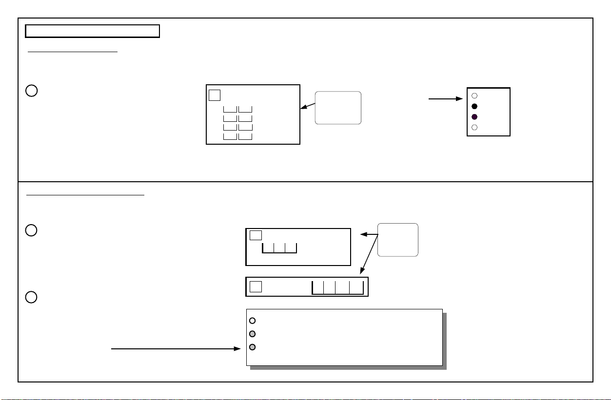
Types of Programming Blocks
LED Programming Block
Enable features by pressing the key that corresponds to the associated feature; the LED will turn ON. To disable a feature press the key again;
the LED will turn OFF. To disable all features within a LED Type Programming Block press the D key; all LEDs will turn OFF.
LED Programming Block Example
1
Program zones 2 and 3 as Follower Zones.
1. Enter Programming Block 02, by pressing
B (Beep), then 02 (Beep).
2. Press the 2 key to select zone 2.
02 Exit/Entry Follower
Default
OFF
OFF
OFF
OFF
Zone 1
Ð
Zone 2
Zone 3
Ð
Zone 4
LED Type
Programming
Block
Zone 2 and Zone 3
LEDs are ON indicating that zones 2
and 3 have been
programmed as follower zones.
ZONE 1
ZONE 2
ZONE 3
ZONE 4
3. Press the 3 key to select zone 3.
Direct Entry Programming Block
Enter data directly. For hexadecimal entries of A-F, use the A key + 1 through 6 keys, respectively. Use the D
key to blank out digits in Direct Entry type programming blocks. Default values are shown in parentheses.
Direct Entry Programming Example 1
1
Program the panel for a 60 second Exit Delay.
1. Press B (Beep) 10 (Beep)
10 Exit Delay
0 6 0 Exit Delay, seconds
(0) (4) (5) Maximum Entry 255
Direct Entry
Type
Programming
Blocks
2. Press 060.
9
E
Direct Entry Programming Example 2
2
Dialing Prefix
44
(Hexadecimal data entry)
Program Telephone Prefix Number with a 9E.
1. Press B (Beep) 44 (Beep).
2. Press 9
3. Press A
ARMED OFF
READY
ü
FLASHING
FLASHINGSYSTEM
Indicates the panel is in
Dealer Program Mode and
the next digit entered will be
interpreted as a Hexadecimal digit. Valid entries are
1-6 (A-F).
4. Press 5
2
Page 3
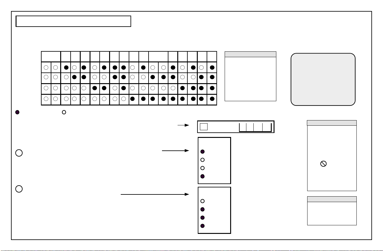
Viewing Data in Programming Blocks
To view data within a programming Block, enter the Program Block Number, then press the C key, continue pressing the C key until all digits within the Programming Block have been viewed. Data will be displayed in the binary format shown in the table below:
0/Blank 1 2 3 4 5 6 7 8 9 *A/0 B C D E F
ZONE 1
ZONE 2
ZONE 3
ZONE 4
ZONE LED ON ZONE LED OFF
Example: Viewing the Dialing Prefix
A Dialing Prefix of 9E has been programmed at Programming Block Number
44 (outside access number). Follow the steps below to view the data.:
Press B44 to enter Programming Block 44. The 1st
1
digit of Programming Block 44 is displayed.
2
Press the B key to view the 2nd digit.
44
Data = 9
Data = E
NOTE:
*
In the following Programming Blocks, data that has
been entered as a ‘0’ will
be displayed as an ‘A’:
Subscriber ID Numbers,
Phone Numbers, Pager
Leading and Trailing digits
and Report Codes.
Dialing Prefix
ZONE 1
ZONE 2
ZONE 3
ZONE 4
ZONE 1
ZONE 2
ZONE 3
ZONE 4
For Technical As-
sistance, Contact
the Napco Toll
Free Helpline (
(800) 645-9440
9
E
NOTE:
The Following Programming Options are not
permitted for UL installations: [05], [06], [23-2],
[26-4] and [26-4].
UL
The symbol by a
programming Block indicates the programming
option is not permitted
for UL installations.
NOTE:
For information about
programming blocks refer to XP-600 Installation
Manual WI854C.
3
Page 4
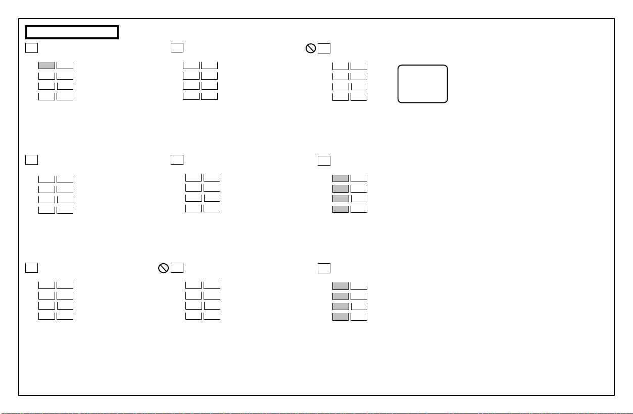
Zone Features
00
Exit/Entry Zones
Default
ON
OFF
OFF
OFF
Zone 1
Zone 2
Zone 3
Zone 4
03
Auto Bypass Reentry Zones
Default
OFF
OFF
OFF
OFF
Zone 1
Zone 2
Zone 3
Zone 4
UL
06
Open Circuit Zones
Default
OFF
OFF
OFF
OFF
Zone 1
Zone 2
Zone 3
Zone 4
See wiring
diagram for
Open Circuit
wiring.
01
Home/Away with Delay Zones
Default
OFF
OFF
OFF
OFF
02
Exit/Entry Follower Zones
Default
OFF
OFF
OFF
OFF
Zone 1
Zone 2
Zone 3
Zone 4
Zone 1
Zone 2
Zone 3
Zone 4
4
04
24 Hour Protection Zones
Default
OFF
OFF
OFF
OFF
05
UL
40 ms Loop Response Zones
Default
OFF
OFF
OFF
OFF
Zone 1
Zone 2
Zone 3
Zone 4
Zone 1
Zone 2
Zone 3
Zone 4
07
Burg (Steady) Output
Default
ON
ON
ON
ON
08
Programmable Output (PGM)
Default
ON
ON
ON
ON
Zone 1
Zone 2
Zone 3
Zone 4
Zone 1
Zone 2
Zone 3
Zone 4
Page 5

System Times
10
Exit Delay
Exit Delay, seconds
(0) (4) (5)
11
Entry Delay
Maximum Entry 255
Entry Delay, seconds
(0) (3) (0)
12
Burg (Steady) Output Time-out
Maximum Entry 255
Bell Time-out, minutes
(0) (0) (5)
13
Reserved
14
Test Timer Interval
Maximum Entry 255
Test Timer, days
(0) (0) (1)
15
Line Cut Time-to-Fail (Disabled = 000)
(0) (0) (0) Enable Feature-Valid Entries 10-255
16
Wireless Supervisory Timer
Maximum Entry 255
Line Cut Time-to-Fail, seconds
Supervisory Timer, hours
(1) (2)
Maximum Entry 26
System Features
20
Keypad Features 1
Default
OFF
OFF
ON
OFF
*See Note 1
21
Keypad Features 2
Default
ON
OFF
ON
OFF
22
Miscellaneous Features 1
Default
OFF
ON
ON
OFF
23
Programmable Output (PGM) Features 1
Default
OFF
UL
OFF
OFF
OFF
*See Note 2
NOTE 1:
Additional programming required for reporting, see Blocks [36]&[56].
Zn 1 LED ON = *Keypad Panic 2 (KK )
Zn 2 LED ON = *Keypad AUX (FF )
Zn 3 LED ON = *Keypad Panic (GG )
Zn 4 LED ON = *Ambush (4th User Code)
Zn 1 LED ON = Audible panic
Zn 2 LED ON = Exit/Entry with Urgency
Zn 3 LED ON = Display Bypass (ARMED)
Zn 4 LED ON = Disable Code Entry Beeps
Zn 1 LED ON = Abort Delay
Zn 2 LED ON = Easy Arm/Easy Exit
Zn 3 LED ON = Swinger Shutdown
Zn 4 LED ON = Bell on Line Cut (Armed)
Zn 1 LED ON = Audio Verification
Zn 2 LED ON = *Access Output (A 3)
Zn 3 LED ON = *Follow Keypad Sounder
Zn 4 LED ON = *Keyfob/Keyswitch Chirp
24
Programmable Output (PGM) Features 2
Default
OFF
OFF
OFF
OFF
25
Programmable Output (PGM) Features 3
Default
OFF
OFF
OFF
OFF
*See Note 3
26
Miscellaneous Features 2
Default
OFF
OFF
UL
OFF
UL
OFF
NOTE 2:
Cannot be programmed with any other Programmable Output (PGM) Feature.
NOTE 3:
Includes Bell Cut, Receiver Fail-to-Respond, Receiver Tamper, Receiver
JAM, Transmitter Low Battery and Transmitter Supervisory Faliure.
Zn 1 LED ON = Reserved
Zn 2 LED ON = AUX
Zn 3 LED ON = Panic
Zn 4 LED ON = Test Timer
Zn 1 LED ON = AC Fail
Zn 2 LED ON = Low Battery
Zn 3 LED ON = *Trouble
Zn 4 LED ON = Armed
Zn 1 LED ON = Momentary Keyswitch Arming
Zn 2 LED ON = Reserved
Zn 3 LED ON = Inhibit Fail to Communicate
Zn 4 LED ON = Inhibit Low Battery Display
5
Page 6

Telephone Number 1 Programming
30
Subscriber ID Number
31
Telephone Number 1
34
Zone Report, Telco 1
Default
ON
ON
ON
ON
Zone 1
Zone 2
Zone 3
Zone 4
37
System Reporting, Telco 1
Default
OFF
ON
OFF
OFF
*See Note 2
Zn 1 LED ON = AC Fail Report (15 min. report delay)
Zn 2 LED ON = Low Battery Report
Zn 3 LED ON = *Trouble Report
Zn 4 LED ON = Reserved
NOTE:
A fixed Dial Tone Detection (E) is included prior to the Dialing Prefix (Block
Number 44). Programming an E is not required for Telco 1, Telco 2 and
Telco 3. If dial tone detection is not desired select No Dial Tone Detection
in Communicator Features (Block Number 46). Program a D if a 4 second
delay is required.
32
Receiver Format
[0] Disabled
[1] Ademco Slow
[2] Radionics Slow
[3] Silent Knight Fast
[4] Universal High Speed
[5] Reserved
[6] Point ID
[7] Pager
33
Receiver Options
Default
ON
OFF
OFF
OFF
Zn 1 LED ON = 2300 Hz Handshake/Kissoff
Zn 2 LED ON = Sumcheck
Zn 3 LED ON = Single Digit
Zn 4 LED ON = No Handshake/Pager Extend
6
(4)
35
Zone Restore Report, Telco 1
Default
OFF
OFF
OFF
OFF
36
System Reporting, Telco 1
Default
OFF
OFF
ON
OFF
*See Note 1
NOTE 1:
Requires features to be enabled, see block [20].
Zone 1
Zone 2
Zone 3
Zone 4
Zn 1 LED ON = *KP Panic 2 (KK )
Zn 2 LED ON = *KP AUX (ff )/Ambush
Zn 3 LED ON = *KP Panic (gG )
Zn 4 LED ON = Test Timer
38
System Restore Report, Telco 1
Default
OFF
OFF
OFF
OFF
39
Opening Closing Report, Telco 1
Default
OFF
OFF
OFF
OFF
NOTE 2:
Includes Bell Cut, Receiver Fail-to-Respond, Receiver Tamper, Receiver
JAM, Transmitter Low Battery and Transmitter Supervisory Faliure.
ZONE 3 TX LOW BATTERY “RF TRAN LOW BAT, ZN03”
Zn 1 LED ON = AC Restore Report
Zn 2 LED ON = Battery Restore Report
Zn 3 LED ON = Trbl Restore Report
Zn 4 LED ON = Reserved
Zn 1 LED ON = User 1 Reporting
Zn 2 LED ON = User 2 Reporting
Zn 3 LED ON = User 3 Reporting
Zn 4 LED ON = User 4 Reporting
Page 7

Backup Telephone Programming
40
Subscriber ID Number (Telco 2)
41
Telephone Number 2
NOTE:
A fixed Dial Tone Detection (E) is included prior to the Dialing Prefix (Block
Number 44). Programming an E is not required for Telco 1, Telco 2 and
Telco 3. If dial tone detection is not desired select No Dial Tone Detection
in Communicator Features (Block Number 46). Program a D if a 4 second
delay is required.
42
Receiver Format
[1] Ademco Slow
[2] Radionics Slow
[3] Silent Knight Fast
[4] Universal High Speed
[5] Reserved
[6] Point ID
[7] Pager
43
Receiver Options
Default
ON
OFF
OFF
OFF
Zn 1 LED ON = 2300 Hz Handshake/Kissoff
Zn 2 LED ON = Sumcheck
Zn 3 LED ON = Single Digit
Zn 4 LED ON = No Handshake
(4)
44
Dialing Prefix
Dialing Prefix for Telco 1, Telco 2
& Telco 3.
45
Communicator Features 1
Default
ON
ON
OFF
OFF
46
Communicator Features 2
Default
OFF
OFF
OFF
OFF
Zn 1 LED ON = Communicator Enabled
Zn 2 LED ON = DTMF w/ Rotary Back up
Zn 3 LED ON = DTMF only
Zn 4 LED ON = Backup to Telco 2
Zn 1 LED ON = No Dial Tone Detection
Zn 2 LED ON = 2:1 Rotary Dialing
Zn 3 LED ON = Backup if < 4 attempts
Zn 4 LED ON = Reserved
7
Page 8

Telephone Number 3 Programming
50
Subscriber ID Number
51
Telephone Number 3
54
Zone Report, Telco 3
Default
OFF
OFF
OFF
OFF
Zone 1
Zone 2
Zone 3
Zone 4
57
System Reporting, Telco 3
Default
OFF
OFF
OFF
OFF
*See Note 2
Zn 1 LED ON = AC Fail Report (15 min. report delay)
Zn 2 LED ON = Low Battery Report
Zn 3 LED ON = *Trouble Report
Zn 4 LED ON = Reserved
NOTE:
A fixed Dial Tone Detection (E) is included prior to the Dialing Prefix (Block
Number 44). Programming an E is not required for Telco 1, Telco 2 and
Telco 3. If dial tone detection is not desired select No Dial Tone Detection
in Communicator Features (Block Number 46). Program a D if a 4 second
delay is required.
52
Receiver Format
[0] Disabled
[1] Ademco Slow
[2] Radionics Slow
[3] Silent Knight Fast
[4] Universal High Speed
[5] Reserved
[6] Point ID
[7] Pager
53
Receiver Options
Default
ON
OFF
OFF
OFF
Zn 1 LED ON = 2300 Hz Handshake/Kissoff
Zn 2 LED ON = Sumcheck
Zn 3 LED ON = Single Digit
Zn 4 LED ON = No Handshake/Pager Extend
8
(4)
55
Zone Restore Report, Telco 3
Default
OFF
OFF
OFF
OFF
56
System Reporting, Telco 3
Default
OFF
OFF
OFF
OFF
*See Note 1
NOTE 1:
Requires features to be enabled, see block [20].
Zone 1
Zone 2
Zone 3
Zone 4
Zn 1 LED ON = *KP Panic 2 (KK )
Zn 2 LED ON = *KP AUX (ff )/Ambush
Zn 3 LED ON = *KP Panic (gG )
Zn 4 LED ON = Test Timer
58
System Restore Report, Telco 3
Default
OFF
OFF
OFF
OFF
59
Opening Closing Report, Telco 3
Default
OFF
OFF
OFF
OFF
NOTE 2:
Includes Bell Cut, Receiver Fail-to-Respond, Receiver Tamper, Receiver
JAM, Transmitter Low Battery and Transmitter Supervisory Faliure.
ZONE 3 TX LOW BATTERY “RF TRAN LOW BAT, ZN03”
Zn 1 LED ON = AC Restore Report
Zn 2 LED ON = Battery Restore Report
Zn 3 LED ON = Trbl Restore Report
Zn 4 LED ON = Reserved
Zn 1 LED ON = User 1 Reporting
Zn 2 LED ON = User 2 Reporting
Zn 3 LED ON = User 3 Reporting
Zn 4 LED ON = User 4 Reporting
Page 9

Report Codes
60
Zone Report Codes
Zone 1 Alarm Code
(3)
Zone 2 Alarm Code
(3)
Zone 3 Alarm Code
(3)
Zone 4 Alarm Code
(3)
61
Point ID Report Codes
Zone 1 Alarm Code
(3)
Zone 2 Alarm Code
(3)
Zone 3 Alarm Code
(3)
Zone 4 Alarm Code
(3)
NOTE:
The second digit of the Report Code is the number of
the zone that is reporting.
For example zone 5 report
code (default of 3) would be
35.
1 FIRE
2 PANIC
3 BURGLARY
4 HOLDUP
5 GENERAL ALARM
6 RESERVED
7 GAS ALARM
8 HEAT ALARM
9 RESERVED
A AUXILIARY
B 24 HOUR ALARM
62
Zone Codes
Zone 1, 2, 3 & 4 Restore Code
(E)
Zone 1, 2, 3 & 4 Trouble Code
(F)
63
System Report Codes
Keypad Panic 2 (KK)
(1) (1)
Keypad AUX (FF)
(2) (3)
Keypad Panic (GG)
(2) (1)
Test Timer
(F) (F)
AC Fail
(F) (9)
Low Battery
(F) (8)
*Trouble
(F) (1)
*See Note 1
64
System Restore Code
(E)
65
Opening and Closing Code
(C)
Closing Code
(B)
Opening Code
66
Ambush Report Code
(2) (2)
Enhanced Communicator Features
67
Telephone Number 1
Default
OFF
OFF
OFF
OFF
68
Telephone Number 3
Default
OFF
OFF
OFF
OFF
Zn 1 LED ON = Opening after Alarm (Cancel Code)
Zn 2 LED ON = Conditional Closing
Zn 3 LED ON = Reserved
Zn 4 LED ON = Reserved
Zn 1 LED ON = Opening after Alarm (Cancel Code)
Zn 2 LED ON = Conditional Closing
Zn 3 LED ON = Reserved
Zn 4 LED ON = Reserved
NOTE 1:
Includes Bell Cut, Fire Trouble, Receiver Fail-to-Respond, Receiver Tamper,
Receiver JAM, Transmitter Low Battery and Transmitter Supervisory Faliure.
9
Page 10

Wireless
Transmitters
71
Zone 1
72
Zone 2
73
Zone 3
74
Zone 4
RF ID # Point
:
:
:
:
Enter the RF ID# located on
the Transmitter and Key Fob
labels.
RF ID # XXXXXX:X
Enter the point number to be
associated with the zone. If only
one point of GEM-TRANS2 is
used, enter a 1 in this location.
For GEM-GB, GEM-DT, GEM-
PIR enter a 1 in this location.
Programming Example
Map point 1 of a window door transmitter, with RF ID# 0012B0:0
to Zone 3.
73 Zone 3
0 0 1 2 B 0 :0 1
1. Enter Dealer Mode.
2. Enter B (beeps)73 (beeps)
3. Enter 0012A200
4. Enter 1 (beeps)
Hexadecimal B Entry
Note: If the RF ID# in step 3 is not entered correctly the
keypad will emit a 1 second tone indicating incorrect entry.
Repeat steps 2 - 4 above.
Keyfobs
81
Keyfob 1
82
Keyfob 2
83
Keyfob 3
84
Keyfob 4
AUX 1 AUX 2RF ID #
:
:
:
AUX 1 & 2
Programming
1 Panic
2 AUX
3 Bell ON
4 PGM
5 Instant
6 Access on PGM
7 Full Set System
8 Interior
:
Hexadecimal Data Entry
To Enter a hexadecimal digit enter the following: A=A1 B=A2 C=A3 D=A4 E=A5 F=A6
10
Page 11

Downloading
90
Callback Telephone Number
91
Ring Count
(0) (9) Maximum Entry 15
92
Downloading Features
Default
ON
OFF
OFF
OFF
93
Auto Download ID Number
Zn 1 LED ON = Ring Method
Zn 2 LED ON = Answering Machine override
Zn 3 LED ON = Command 6(A6) Download
Zn 4 LED ON = Reserved
Dealer Programming
94
Dealer Code
(4) (5) (6) (7)
95
User 1 Code
(1) (2) (3) (4)
96
Dealer Options 1
Default
OFF
ON
OFF
OFF
Zn 1 LED ON = Dealer Code Lockout
Zn 2 LED ON = User 1 Code Lockout
Zn 3 LED ON = Reserved
Zn 4 LED ON = Reserved
97
Dealer Options 2
Default
OFF
OFF
OFF
OFF
*See Note 1
98
Number of Re-Dials
Zn 1 LED ON = *International Dialing Protocol
Zn 2 LED ON = *Invert Bell Output
Zn 3 LED ON = System Trouble Auto Reset
Zn 4 LED ON = User 1 Code-Program only
(9)
NOTE 1:
International Features
11
Page 12

E1
E2
+ RED
RECHARGEABLE
BATTERY
12 VDC 4AH OR 7AH
BLACK
COLD WATER GROUND
CONNECTION
USE ONLY COLD-WATER
PIPE OR BURIED GROUND
ROD. USE AT LEAST #16
AWG WIRE.
2.2K
(E)
EZ
Zone
Doubling
Resistors
RED
TM
RED RED
GOLD
EARTH
GROUND
3.9K
(Z)
WHITE RED
GOLD
ORANGE
(1) ALL ZONE RESISTORS MUST BE INSTALLED,
EVEN IF ZONE IS NOT USED.
(2) COMBINED STANDBY = KEYPAD CURRENT +
AUX POWER CURRENT + PGM CURRENT.
XP-400 WIRING DIAGRAM
(REFER TO INSTALLATION INSTRUCTIONS WI853C)
RESIDENTIAL BURG (4 HOUR STANDBY)
COMBINED STANDBY = 350 mA BELL = 2.0 AMP
16 VAC 20 VA
TRANSFORMER
NAPCO TRF12
(OR EQUIVALENT
SEE WI879A).
Class 2
Transformer.
DO NOT
connect to
switched
outlet.
3.9K
(Z)
(1)
ZONE 3
2.2K
(E)
ZONE 1
Normally Open Zone Wiring
Wire the normally
open contact
as shown (Zone 4).
Program the
zone for
Open Circuit [06]
operation.
(2)
ALL OUTPUTS ARE CURRENT LIMITED
NOT USED
-4 +5 +6 1 2 +3
-7 +8 -9
+10 -11 +12
BELL
GND +PWR GND GREEN TIP RING TIP RING
+
3.9K
(Z)
ZONE 4
+
2.2K
ZONE 2
3.9K
ZONE 4
2.2K
(E)
ZONE 1
(E)
(Z)
2.2K
2.2K EOLR
(SUPERVISED)
(E)
-13 14 15 16 17 18 19
PGM
(-)
REMOTE BUS
RED
GRN
BLK
AUX POWER OUTPUT 10-12.5 VDC
RPX-4
GEM-RECV-XP8
(+)
+PWR
50 mA MAX.
LOAD
12
TELCO
RED
Programmable
Output
DISCONNECT TELEPHONE
LINES PRIOR TO SERVICING
PHONE
GRAY
GRN
BRN
To RJ31X
(Supervised)
WARNING
TO PREVENT RISK
OF ELECTRIC SHOCK
12
 Loading...