

Page 1

R
333 Bayview Avenue
Amityville, New York 11701
For Sales and Repairs, (800) 645-9445
For Technical Service, (800) 645-9440
© NAPCO 2004
SVLBKT
UNIVERSAL SWIVEL BRACKET
INSTALLATION INSTRUCTIONS
WI462A 8/04
The SVLBKT Universal Swivel Bracket is used
to mount Napco space-protection units against
a wall and provide vertical and horizontal tilting.
It will accommodate all current models except
DX-Series Double-Techs and M9000-Series
Monitors, each of which is supplied with its own
integral swivel bracket. The SVLBKT bracket
can mount onto a single-gang box using the
screws supplied, or it may be mounted directly
onto the wall using appropriate screws.
The bracket kit comprises the following parts:
(1) Wall Plate
(2) Housing Brackets (select one)
(1) Ball Bracket
(2) Ball Halves
(1) 6-32x5/8" Hex Head Machine Screw
(2) #6x5/16" Self-Tapping Screws
(3) #6x7/16" Self Tapping Screws
(2) 6-32x1/2" Machine Screws
(1) 6-32x3/8" Thread-Forming Hex Slotted Screw
(1) 1/4" Box Wrench is supplied.
BRACKET ASSEMBLY INSTRUCTIONS
1. Referring to the illustration (see reverse), untapped wall plate hole (E) must first be
tapped with threads by use of the 6-32x3/8"
thread-forming Hex slotted screw. After
threads are tapped into this hole, remove the
Thread-Forming Hex Slotted Screw from the
wall plate hole.
2. Referring to the illustration, slip each Ball Half
through the Ball Bracket, then fit the two
halves together.
3. Insert the tab on the Ball Bracket into the slot
in the Wall Plate. Then, install the 6-32,5/8"
Hex Head Machine Screw through the small
hole in the Ball Bracket and into the Wall
Plate--but do not tighten fully.
4. Select the Housing Bracket that fits the unit to
be mounted. Secure the Housing Bracket to
the ball using the two #6x5/16" Self-Tapping
screws.
5. Pull about 6 inches of cable through the Wall
Plate, the ball and the Housing Bracket. With
Hex-Head screw positioned above the ball,
attach the Wall Plate to a single-gang box using the supplied 6-32x1/2" Machine Screws,
or attach directly to the wall with screws suitable for the mounting surface.
6. Punch out the three mounting holes in the
rear wall of the sensor (one at the top; two at
the bottom) corresponding to those in the
Housing Bracket. Also punch out the wireentry hole at the bottom of the rear wall
(between the two lower mounting holes). Pull
the cable through the wire-entry hole, then attach the rear case of the unit to the Housing
Bracket using the three #6x7/16" SelfTapping Screws.
7. Trim the wires so that approximately 2" enters the case and strip the insulation back
about 1/4". Remove the circuit board by removing the Height Scale Lock Screw; this will
greatly facilitate wiring. Complete the connections to the sensor.
8. Replace the circuit board, setting the Height
Scale to the mounting height of the sensor.
Seal the wire-entry hole using the caulking
material supplied. Replace the front cover
and make the required coverage-pattern tests
and adjustments. Use the supplied wrench to
loosen and tighten the Ball Bracket hex-head
screw between checks.
Page 2
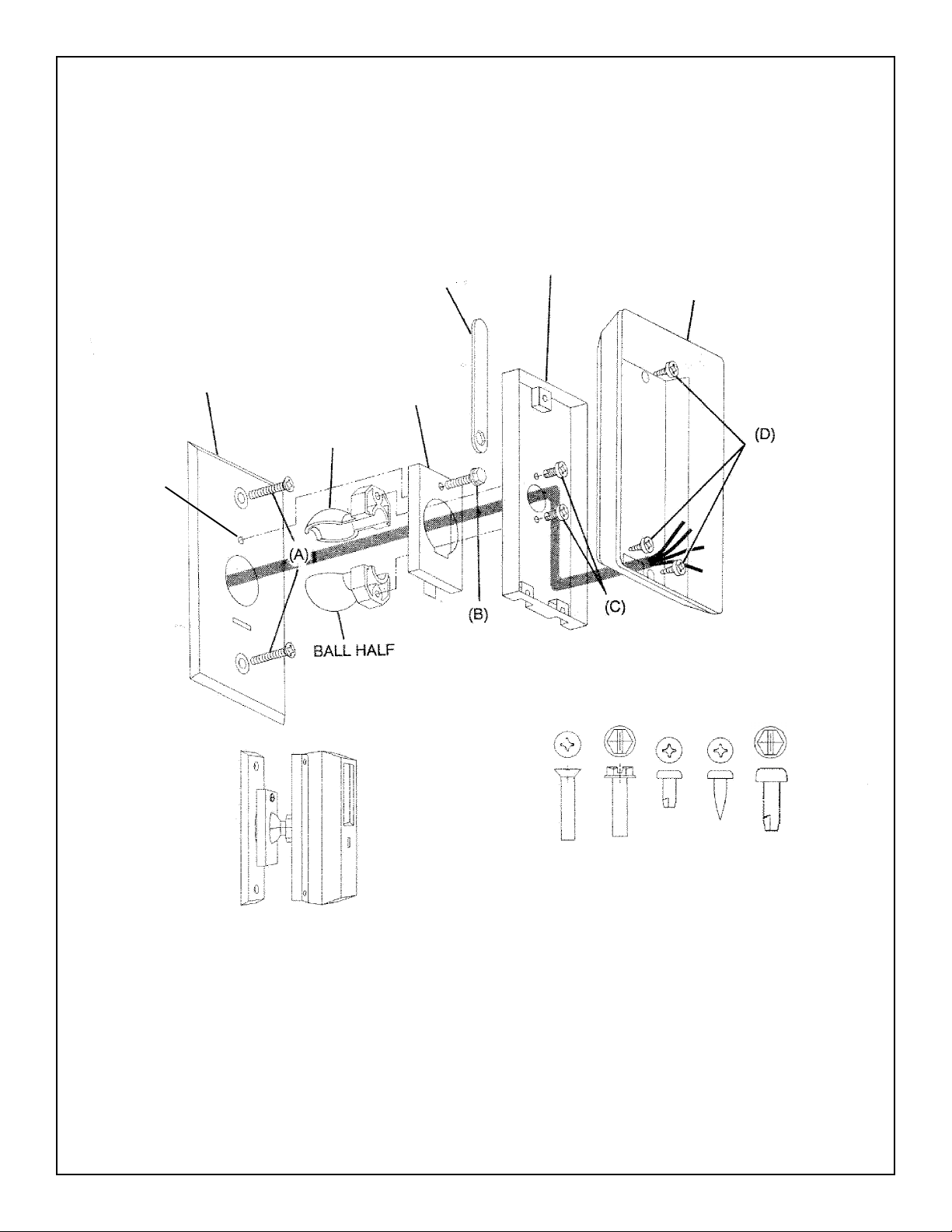
WRENCH
HOUSING BRACKET
SENSOR HOUSING
WALL PLATE
(E)
BALL BRACKET
BALL HALF
(A)
(B)
(C)
(D)
(E)
ASSEMBLED BRACKET WITH SENSOR
SCREW TEMPLATE (ACTUAL SIZES)
(A) 6-32X1/2" MACHINE SCREW
(B) 6-32X5/8" HEX HEAD
(C) #6X5/16" SELF-TAPPING
(D) #6X7/16" SELF TAPPING
(E) 6-32X3/8" THREAD-FORMING HEX SLOTTED
 Loading...