

Page 1
R
333 Bayview Avenue
Amityville, New York 11701
For Sales and Repairs, (800) 645-9445
For Technical Service, (800) 645-9440
Publicly traded on NASDAQ Symbol: NSSC
© NAPCO 2005
PCD-MANAGER
User's Guide
OI303 12/05
NAPCO PCD-Manager Software
Operation User's Guide
1
Page 2

Table of Contents
About This Manual ............................................................ 2
System Requirements .......................................................2
Access Control System Overview .....................................3
Quick Start Checklist .........................................................4
Software Setup and Installation ........................................5
Startup and Login ..............................................................6
Master and Corporate Users ............................................. 7
Preferences ......................................................................8
Account Features ............................................................10
Personnel: Adding / Editing / Deleting ............................13
Personnel: Importing Text File Names ...........................14
Assigning Cards .............................................................. 15
Cards: Access Groups ..............................................16
Cards: Access Group Schedules ..............................18
Cards: Access System Information ...........................19
Automation Relay Schedules ..........................................26
All Schedules ..................................................................27
Logs ................................................................................28
Index ...............................................................................30
NAPCO LIMITED WARRANTY .......................................32
Alarm Users .................................................................... 21
Alarm User Schedules ...............................................23
Alarm System Information ..........................................24
System Requirements
SYSTEM HARDWARE
1. One unused RS-232 serial communications port
(Com 1-8) and a Gem-RS232 module for local serial
connection, or USB to Serial Bus Adapter.
2. A Standard CAT5 network cable for connection to
the LAN, and access to a Local Area Network (when
used with TCP/IP or multiple users).
3. Windows-based PC (with networking capability, if
used).
4. 256MB RAM.
5. An IBM-compatible PC, 1GHz speed or faster.
6. Video resolution of 800 x 600 or higher
SYSTEM SOFTWARE
1. W indows XP Professional ONLY.
2. Microsoft Internet Explorer 5.01 or later.
3. For installation and updates, administrator permissions on the computer (Windows XP Pro) is required.
4. For installation and updates, stop or turn off all antivirus, personal firewall, and other monitoring services.
5. Perform all Microsoft updates prior to installation.
COMPATIBLE USB ADAPTERS
• Saelig USB-COM, Belkin F5U103 (Discontinued),
Keyspan 19HS, USB UMC-100, and FTDI
FT8U232AM.
Windows is a registered trademark of the Microsoft Corporation.
Other products, product names and services described in this manual are for identification purposes only and may be trademarks of their respective companies.
2
Page 3

Access Control System Overview
ACCESS CONTROL
Access control allows you to extend or restrict admittance to a secured area of a protected premises. Cards
with proper credentials that are presented to a card
reader will release a door locking mechanism (such as a
magnetic lock or electric strike). For cards without
proper credentials, the system will prevent access.
NAMES > CARDS > GROUPS > SCHEDULES
At its most basic, access control usually involves a
building, a large number of people, and the idea of allowing or denying the people access to that building during certain times. Therefore, it makes sense that the
first step should be to add the names of people into the
system, each name unique, to distinguish between individuals.
Once names are added, the next step is to assign a
specific proximity card (or cards) to each person
(proximity cards and readers now being commonly
used).
Next, as with many access control systems, it is convenient for large numbers of similar users to be grouped
together--controlled all at once rather than individually-saving time and effort. For example, if the building is a
place of employment, many people working in the building tend to share common working hours, lunch hours,
holidays, etc. Once these "Access Groups" of people
are conceived and organized, they can be created
within PCD-MANAGER, with all of its attributes
(scheduled times such as "active" working hours,
"inactive" holiday hours, etc.) all specified in detail. Access Groups, therefore, are controlled by "schedules"; a
person who possesses a proximity card which is assigned to a specific Access Group is therefore controlled
by the schedule of that Access Group. The schedule
defines when that Access Group is enabled in the system, thus controlling access to the building.
These interconnected relationships--names assigned
to cards assigned to groups assigned to schedules-may best describe the PCD-MANAGER software at its
most basic.
The basic steps are as follows:
1. Add names of people to the program (add
"Personnel") (see page 13)
2. Assign names to specific cards (see page 15)
3. Create Access Groups and configure individ-
ual schedules for each (see pages 16-18)
4. Assign cards (Card Holders) to Access
Groups (see page 15)
The basic steps for adding Alarm Users are:
1. Create Alarm Users from the list of Personnel
2. Create Schedules for Alarm Users
3. Assign Alarm Users to Alarm User Schedules
3
Page 4

Quick Start Checklist
STEPS NEEDED TO GET UP AND RUNNING
FOR CARD HOLDERS:
❒ 1. Assign Names to Proximity Cards. See page 15 for details.
❒ 2. Create Access Groups for Card Holders. See page 15 for details.
❒ 3. Configure Schedules for each Access Group. See page 16 for details.
❒ 4. Assign Card Holders to Access Groups. See page 15-16 for details.
FOR ALARM USERS
❒ 1. Create Alarm Users, if you want to assign someone a keypad user code
(instead of--or in addition to--a proximity card). See page 21 for details.
❒ 2. Create Schedules for Alarm Users, to determine when their keypad user
codes are active. See page 22 for details.
:
❒ 3. Configure Schedules for each Alarm User. See pages 21-23 for details.
4
Page 5
Software Setup and Installation
Installing the PCD-MANAGER Software
INSTALLATION VIA CD-ROM
1. Close any programs (including any anti-virus, antispyware, and monitoring tools) before starting your
installation.
2. Insert the CD-ROM into the drive.
3. If Auto Start is enabled for the CD-ROM drive, the
installation should start on its own. Otherwise, from
Windows Explorer, double click on the file startup.exe
on the CD-ROM--or--from the Start menu, select Run,
then type: <Your CD-ROM Drive Letter>:\startup.exe,
and click Open and OK.
4. Follow the screen instructions. You may need to
restart Windows after the installation has completed.
5. It may be necessary to repeat steps 3 and 4, if the
install process found it necessary to install a Service
Pack.
NOTE: A "DOT NET" folder exists under the Install
Components folder on the PCD-MANAGER
installation CD. If you have a .NET installation error,
manually install the .NET object from the CD.
Network Installations
rate user computer.
4. Point the database to the database host (see Pass-
word Screen Menus, Database Selection on page
6).
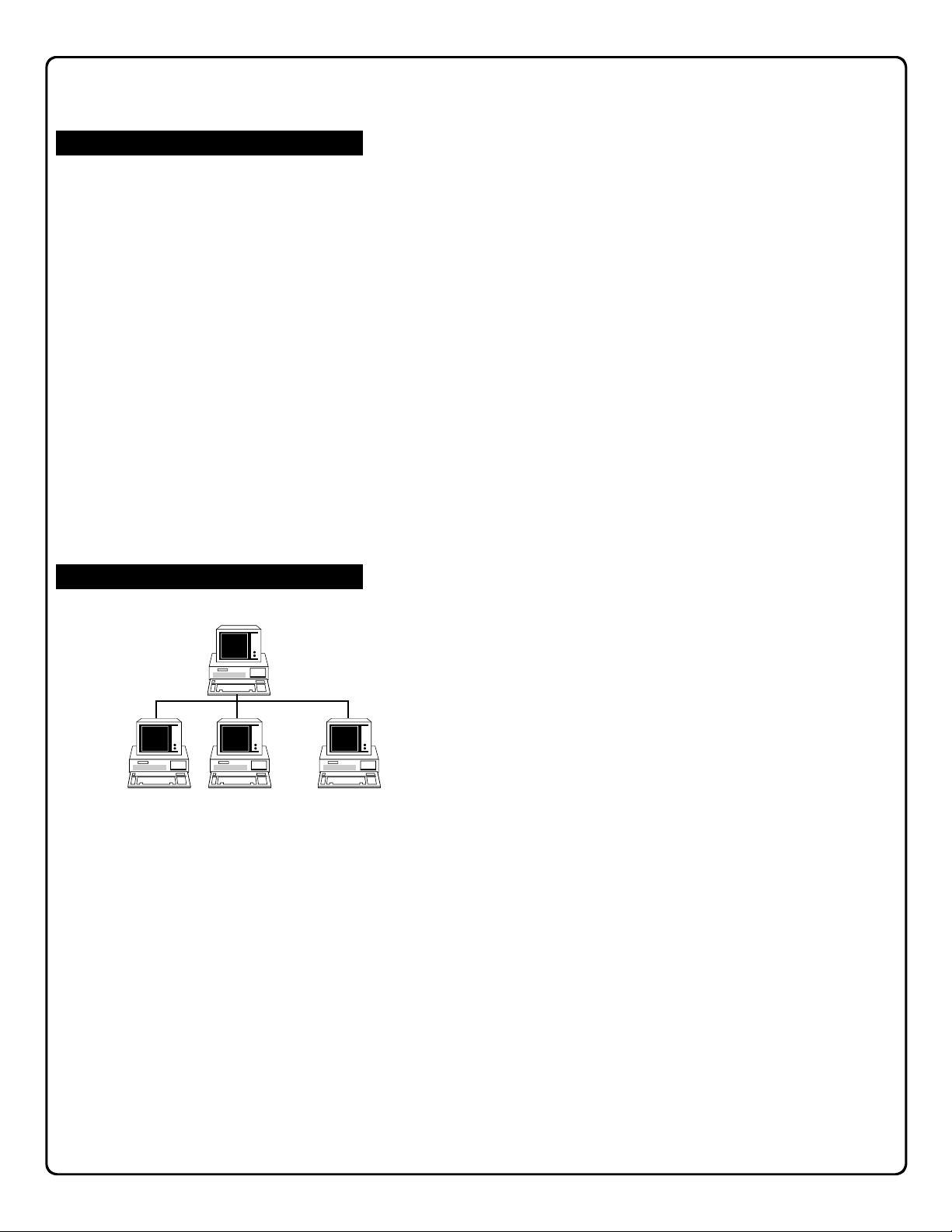
Monitor and Control
From the corporate user screen, the Master user can:
• Check which users are logged on
• Check which accounts have been opened
• Force a user off the database
Database Host
. . .
User 1 User 2
With PCD-MANAGER, one Master and 16 pre-defined users and passwords can all be logged into the same network
database at the same time, making multi-user network access to a centralized database very easy to implement. To
create a network, each with a separate software installation
accessing the same database host machine, proceed as
follows:
Creating a Network Database
1. Copy or move an existing database (or create new database files) into a network directory. The computer on
which this network directory resides can be referred to
as the "Database Host".
2. Add users to the corporate Users list.
User Machines
3. Install the PCD-MANAGER software onto each corpo-
User 15
5
Page 6
Startup and Login
Running the PCD-MANAGER Software
STARTING THE PROGRAM:
From the Start Menu, select Programs, Napco Security Group, PCD-MANAGER.
NOTE: "Napco Security Group" is the default Group
name, and may have been manually changed during
the installation.
Login
Access to the program requires an acceptable Login
Name and Password. The Login Name must be between
1-8 characters in length and the Password must be be-
tween 1-8 characters in length.
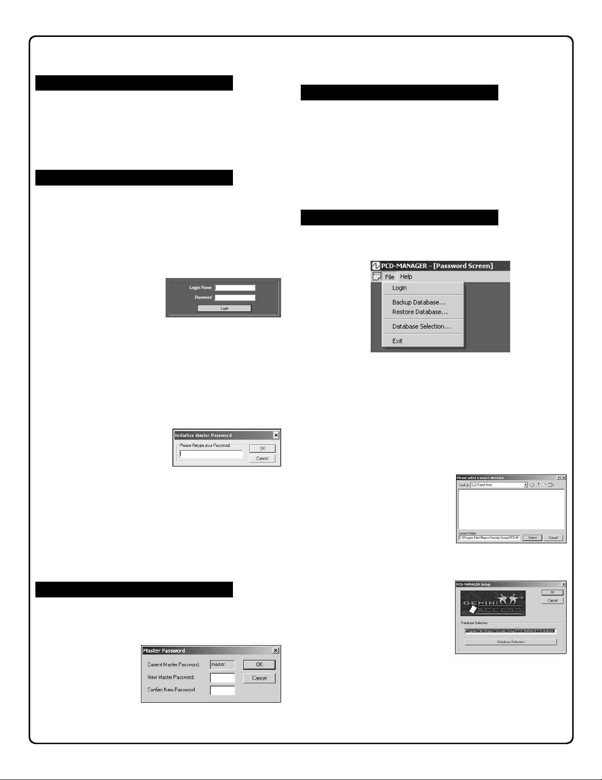
PASSWORD SCREEN:
The first screen that appears after starting the program is
the Password Screen:
First Time Login:
• The first time you
login and create the
database, you must
type "master" as the Login Name and type any password that conforms to the above requirements.
• When entering a password for the first time, you must
retype the same password to confirm (in the Initialize
Master Password screen:
Retype your password and click OK or click Cancel to
select a new password.
IMPORTANT! We
HIGHLY recommend
you keep a written
record of your password in a safe place! If you misplace this password, you will NOT be able to access the program as the master user again.
Master Password
The Master Password can be changed by logging in as
Master and clicking Tools, Master Password in the PCDMANAGER main toolbar. In the Master Password dialog,
type the new Master Password in
the field provided,
and re-type the
same password in
the Confirm New
Password field.
Click OK to save or Cancel to exit without saving.
Logout
The user can log out of PCD-MANAGER at any time,
only allowing other users with proper passwords to enter
the system. Log off by clicking File, Logout from the
PCD-MANAGER main toolbar. The Password Screen
opens, awaiting a Login Name and Password.
Password Screen Menus
The PCD-MANAGER Password Screen contains two
menu items:
FILE
Login - Equivalent to the Login button, initiating the log
on process.
Backup Database - User can backup PCD-
MANAGER database files for safety or sharing purposes. Backed up files are located in the Export Area
folder in the installation directory.
Restore Database - User can receive previously
backed up files (for example from a separate PCDMANAGER installation)
and return the software to a
previously saved state.
Click to open the dialog
(shown at right), which allows the specific database
files to be selected:
Database Selection - Click to select the specific data-
base to open. Note that
multiple software installations can be used, each
pointing to one network
location.
Exit - Click to quit the pro-
gram.
HELP
About PCD-MANAGER - Displays Copyright details,
build number records, database information, etc.
6
Page 7
Master and Corporate Users
Two User Types
In general, PCD-MANAGER has two types of corporate
users who can log into the software:
• A master user
• A group of normal corporate users
At the first-time startup, PCD-MANAGER requires the master user to supply a login name and password. Multiple
copies of PCD-MANAGER may be run at the same time
from different PC's; however each copy must be signed in
with a different login name. Only one login name of either
type may be signed in to PCD-MANAGER at a time.
Master Corporate User
A master user can assign, modify and delete normal users (along with their corresponding properties). By de-
fault, when PCD-MANAGER is run for the first time, the
"Login Name" of the master user will be either "master" or
"MASTER".
The master password can only be changed by the master user. When the master user is signed-in to PCDMANAGER, full privacy and communications privileges
allow additional window menu items to be enabled for the
master user that are not available to normal corporate
users. The enabled selections in the File menu are as
follows:
• New Account
• Copy Account
• Copy to Other Accounts
• Delete Account
• Import Personnel From File
Passwords
To change the master password, log into PCD-MANAGER
using the existing master password. Click Tools, Master
Password, and the following dialog appears:
In the New Master Password field, type a new master password (maximum 8 characters) and retype to confirm. If
both passwords do not match, the following warning popup
appears:
After entering new password, click OK to save or click Can-
cel to exit without saving.
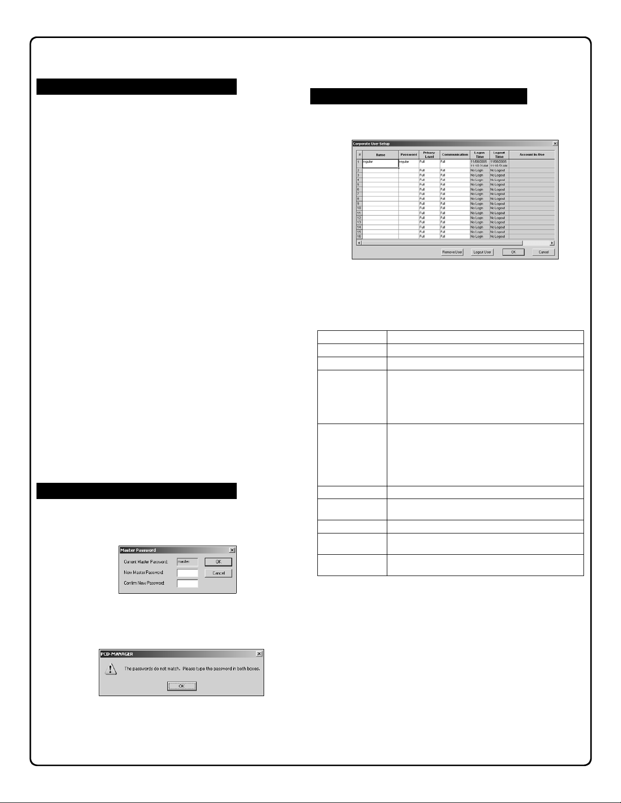
Normal Corporate Users and their Properties
Click Tools, Corporate User Setup, and the following dialog appears.
In the above dialog, a master corporate user can assign
restrictions to each normal corporate user in order to prevent them from accessing certain features in the PCDMANAGER software. The table below summarizes the
properties of a normal user.
Properties Selections
User Name PCD-MANAGER operator name.
User Password PCD-MANAGER operator password.
User Privacy Level Select as follows:
Communication Controls user access to alarm system, as follows:
Logon Time Displays date/time operator logged in to PCD-MANAGER.
Logout Time Displays date/time operator logged out of PCD-MANAGER.
Account In-Use Displays name of account currently open by operator.
Remove User button Master user can click to permanently remove the highlighted
Logout User button Master user can click to manually logout the highlighted user
1. Full – Operator has full read/write software access.
2. Read-Only – Operator has read only access. Control panel
user/card codes are hidden. Note: When selected, the
Communication selections (see next row in this table) are
limited to Upload-Only and None.
1. Full – Operator has full download/upload communication
access to PCD-MANAGER. Selection not available if User
Privacy Level (above) set to Read-Only.
2. Upload Logs Only – Operator can upload event logs except
panel dealer information. No downloading allowed.
3. None – Operator has view-only access. Codes not visible.
Operators still logged in display "Not Logout".
user from the system.
from the system.
After making selections, click OK to save or click Cancel to
exit without saving.
7
Page 8
Preferences
Customize PCD-MANAGER
Various features and settings within the PCD-MANAGER
software can be customized. Click Tools, Preferences in
the PCD-MANAGER toolbar. The Preferences dialog
opens:
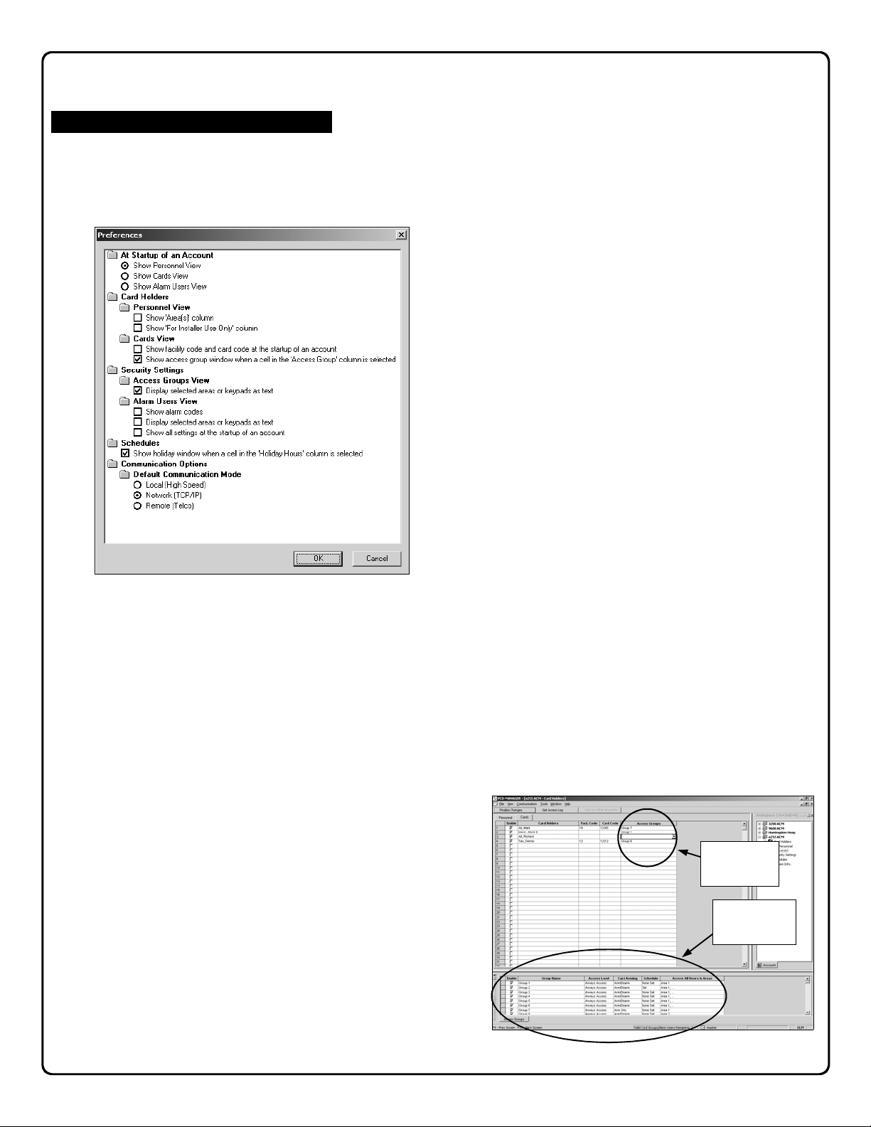
The Preferences dialog allows the following changes to be
made (by clicking radio buttons or check boxes) to the
PCD-MANAGER software:
At Startup of an Account
Show Personnel View - When the PCD-MANAGER
software first opens (just after logging in), the first view
that appears, by default, is the Personnel View (see im-
age on page 13).
The Personnel View allows users to easily add names to
the access control system. The first step for programming almost any access control system tends to be the
process of adding names, therefore this view was selected, by default, to be the first to appear. However, either of two other views can be selected to appear after
startup, if desired:
• Show Cards View
• Show Alarm Users View
The Show Cards View (see page 15) displays the Cards
tab of the Card Holders menu, allowing users entered in
the Personnel tab to be selected as cardholders and to
be assigned to specific cards and into specific groups.
The Show Alarm Users View (see page 21) displays
the Alarm Users tab of the Security Settings menu, allowing users entered in the Personnel tab to be selected
as alarm users and to be assigned individual alarm codes
and attributes (system abilities, area assignments, etc.).
Card Holders
Personnel View - Show 'Area(s)' Column: When
checked, an Area(s) column is added to the Personnel
tab of the Card Holders menu (see image page 13).
When clicked, the Area(s) column displays a table indicating the areas to which the selected user has access.
Personnel View - Show 'For Installer Use Only' Column: When checked, a For Installer Use Only column
is added to the Personnel tab of the Card Holders menu
(see image page 13). When clicked, the column displays
a table indicating data from the control panel regarding
Access Groups and Alarm Users for that selected user.
This is a reference for your dealer, in case he needs to
modify a user locally from the keypad or remotely via the
PCD-Windows QuickLoader. The numbers presented in
this column are the actual control panel user numbers,
assigned by PCD-MANAGER itself. Also note that, for
example, if an individual only has one card assigned then
only one number will display, If they have three cards and
an alarm code then four numbers will display).
Cards View - Show facility code and card code at the
startup of an account: When checked, the Cards tab of
the Card Holders menu displays a Facility Code column
and a Card Code column indicating the properties of the
assigned card(s). Even if these columns are not normally
set to display, they can be made to display simply by
clicking on an empty cell in the Card Holders column
(since at this time the software anticipates a new card is
being entered).
Cards View - Show access group window when a cell
in the 'Access Group' column is selected: When
checked, the Cards tab of the Card Holders menu displays an Access Groups window at the bottom of the
screen when a cell is clicked in the Access Groups col-
umn (see image below). Note: This preference is en-
abled by default.
Click an
Access Group
cell here...
...and an
Access Group
window opens.
8
Page 9
Preferences (cont'd)
Security Settings
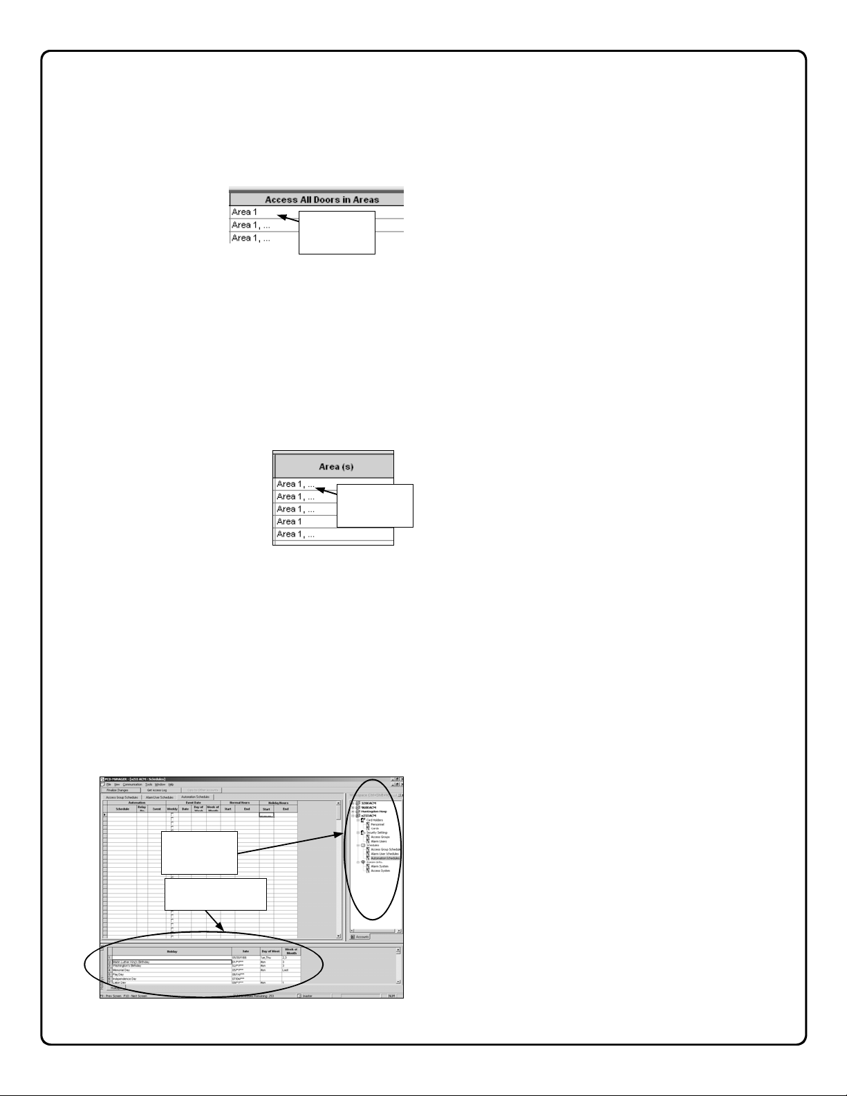
Access Groups View - Display selected areas or keypads as text: When checked, full text names of areas
are displayed in the Access All Doors in Areas column
(located in the Access
Groups tab of the Security Settings menu).
An example is shown in
the image at right:
Alarm Users View - Show Alarm Codes: When
checked, the Alarm Code column is displayed in the
Alarm Users tab of the Security Settings menu. The
Alarm Code column displays a 3-6 digit alarm control
panel code. See page 21 for a sample image of this column.
Alarm Users View - Display selected areas or keypads as text: When checked, full text names of areas
are displayed in the Areas column (located in the Alarm
Users tab of the Security Set-
tings menu). An example is
shown in the image at right:
Alarm Users View - Show all settings at the startup of
an account: When checked, all columns are displayed in
the Alarm Users tab of the Security Settings menu. See
page 21 for a sample image.
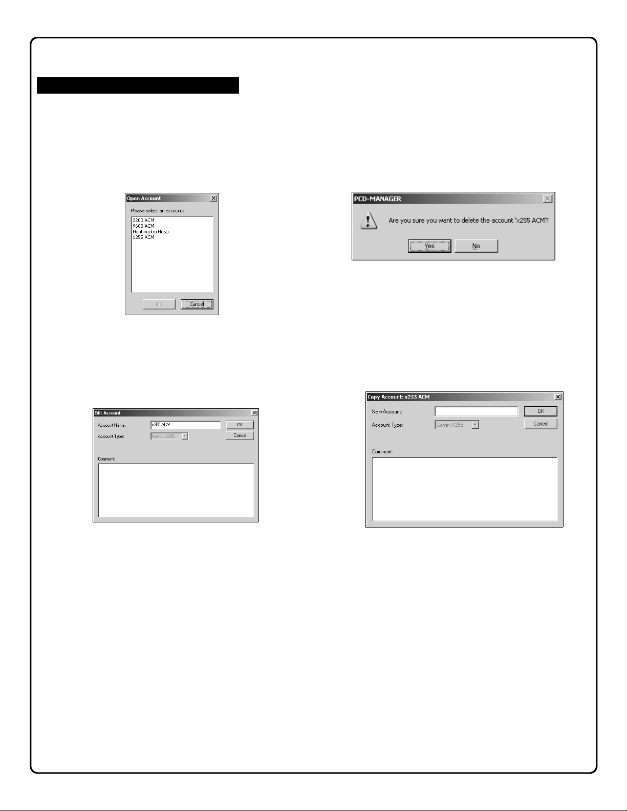
Schedules
Show Holiday window when a cell in the 'Holiday
Hours' column is selected: When checked, the Sched-
ules menu displays a "Holiday" window at the bottom of
the screen when any cell is clicked in the Holiday Hours
column (see image below). Note: This preference is enabled by default.
Holiday Hours
cell here...
...and a "Holiday"
Click a
window opens.
Full text
names are
displayed
Full text
names are
displayed
9
Page 10
Overview
Account Features
Open Account
To open an account, click File, Open Account in the PCD-
MANAGER toolbar. The Open Account dialog opens, al-
lowing the selection of existing accounts within PCDMANAGER. Click to highlight an account name, and click
OK to open the selected account, or click Cancel to exit
without opening.
Note: If no accounts exist in the software, the File, Open
Account menu item is "grayed-out" (unavailable).
Edit Account
To edit an account, first open the account and then click
File, Edit Account. The Edit Account dialog opens:
The Edit Account dialog includes the following fields:
• Account Name - Type a unique name (maximum of 8
characters allowed)
• Account Type - Press Shift+F5 and click on the Ac-
count Type pull-down menu to edit the alarm control
panel type used in the ACM system. Currently, three
panels are available: GEM-X255, GEM-P9600 and
GEM-P3200.
Either click Cancel to exit without saving, or click OK to
save the changes. Note: If no accounts exist in the software, the File, Edit Account menu item is "grayedout" (unavailable).
Close Account
To close an account, click File, Close Account in the
PCD-MANAGER toolbar.
When an account closes, all of the PCD-MANAGER windows related to that account close as well.
Note: If no account is open, the File, Close Account
menu item is "grayed-out" (unavailable).
Delete Account
To delete an open account, click File, Delete Account in
the PCD-MANAGER toolbar. A popup will appear requesting confirmation of the deletion (shown below).
Click Yes to delete the displayed account or click No to
cancel the deletion. Note: Users cannot delete an account
that is currently in-use by other users. Note: If no accounts exist in the software, the File, Delete Account
menu item is "grayed-out" (unavailable).
Copy Account
To copy an open account, click File, Copy Account in the
PCD-MANAGER toolbar. The Copy Account dialog
opens:
The Copy Account dialog includes the following fields:
• New Account - Type a unique name for the copied
account (maximum of 16 characters allowed)
• Account Type - Press Shift+F5 and click on the Ac-
count Type pull-down menu to edit the alarm control
panel type used in the ACM system. Currently, three
panels are available: GEM-X255, GEM-P9600 and
GEM-P3200.
• Comment - Type any comments to assist in describing
the copied account (maximum of 160 characters allowed)
Either click Cancel to exit without copying, or click OK to
copy the open account.
Note: If no accounts exist in the software, the File, Copy
Account menu item is "grayed-out" (unavailable).
10
Page 11

Account Features (cont'd)
Copy to Other Accounts Button
Note: The Copy to Other Accounts button is enabled
only when the Personnel screen is open and when multi-
ple accounts exist in the software (otherwise this button will
be grayed-out).
The Copy to Other Accounts button is designed to propagate changes made within one account into other accounts
within PCD-MANAGER (each account representing a control panel). In multiple-panel ACM installations, it is often
necessary to enable users access system-wide (between
control panels within one building).
To propagate new or existing personnel assignments from
one account to another, first highlight the last names of the
users you wish to copy, then click the Copy to Other Ac-
counts button. The following dialog opens:
Select the accounts into which the personnel are to be copied, and click Copy to continue or Cancel to exit.
Note: When copying personnel data into other accounts,
all attributes are copied except for internal software number
designations (such as user numbers and schedule numbers). These number designations, for all accounts, are for
internal software use only, and are intended to be transparent to the corporate user.
Finalize Changes Button
Click to send all new or changed data (such as new cards,
access groups, alarm users, schedules, etc.) to the control
panels to be put into use.
When the Finalize Changes button is clicked, a confirmation dialog appears (a typical example is shown below) providing a list of the screens modified and to be changed
within the system.
Click Cancel to exit without saving changes or click OK to
process the changes and put them into use. When OK is
clicked the Error Check utility will automatically run (by default), as described in the section that follows.
Error Checking
To ensure all changes made within PCD-MANAGER do not
conflict with any new or existing control panel programming,
an error checking utility is included with the software. The
error checking utility will run when PCD-MANAGER begins
communication with the control panel, and is a default selection within the Preferences screen (see page 9 for more
information).
If enabled by the Preferences screen, when OK is clicked
in the Finalize Changes confirmation dialog (described in
the previous section above), the error checking utility will
automatically run. A communications "status" screen
(shown below) will open at the bottom of the window, allowing the corporate user to remain informed of the panel
downloading progress and results. Control panel communication will only continue if no errors are found
Note: Users can also initiate the error checking utility by
clicking Tools, Error Checking on the PCD-MANAGER
toolbar.
In the Error Checking window (shown above), users can
double-click on an error listed and the selection will automatically jump to the specific field within PCD-MANAGER
where the error originates.
Printing
The PCD-MANAGER software allows the printing of the
following information within each account:
• Alarm system users and their corresponding attributes.
11
Page 12

Account Features (cont'd)
• Card Holders and their corresponding attributes (only if
the alarm system supports an ACM).
• Scheduled events and holiday dates.
• ACM logs (only if an alarm system supports an ACM).
Workspace
"Workspace" area
Press Ctrl + Shift + W
to open and close
The Workspace (shown above) allows account features
and settings to be presented in one convenient location.
Accounts, each representing a control panel, can easily be
selected by simply clicking the account name in the Workspace. Features associated with the account automatically
open in a directory tree structure.
You can also right-click in the Workspace to open a menu
list of options available, shown below.
In addition to the options mentioned previously (New Ac-
count, etc.), the Workspace can be Hidden (click Hide)
and can be moved to the right or left side of the PCDMANAGER window (click Dock to Left or Dock to Right.
The image below displays PCD-MANAGER with the Workspace "docked" to the left:
12
Page 13

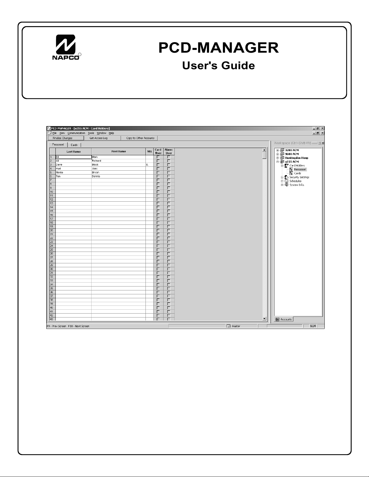
Personnel: Adding / Editing / Deleting
Card Holders > Personnel
Click here and type
names in this column
to add users
"Workspace" area
Press Ctrl + Shift + W
to open and close
The Personnel tab of the Card Holders menu allows entry
of new personnel into PCD-MANAGER.
After entering personnel names into this screen (shown
above), the names can be copied into other areas of the
software where they are assigned as alarm system users or
card access users or both. In this window, personnel
names are listed by Last, First and Middle Initial, and as a
convenient reference, the window also displays whether
personnel have been assigned as a Card User or as an
Alarm User. Note: These columns reflect the user data
that has been downloaded into the control panel. The Mid-
dle Initial ("M.I.") must be only one character followed by a
period.
The list is alphabetical, therefore people with multiple cards
(or those with lost/disabled cards) will have their names displayed next to each other, thus finding users is simple and
convenient.
By default, the Personnel tab is opened by simply clicking
an account listed within the Workspace (the Workspace is
open by default, but can be closed and opened by pressing
Ctrl + Shift + W).
The names can be entered by:
• typing in the names manually via a computer keyboard
• importing names from any comma delimited file (see
page 14)
See page 8 to set Preferences to allow this window to display the Areas to which each individual has access.
The Personnel tab of the Card Holders menu works like
other standard Windows applications; the columns can be
adjusted by placing the mouse arrow between columns (the
arrow changes to a "column adjuster" icon), and if many
names are entered, you can scroll down the list of names
as needed. In addition, you can edit names by clicking and
re-typing text, and a whole column of names can be copied
by clicking the column header to highlight the entire column
and copying the data to the clipboard.
13
Page 14

Overview
Personnel: Importing Text File Names
To import only the names of personnel into PCDMANAGER, names listed in a comma delimited text file
(.txt) can be used. The names listed in the .txt file must
exist in a certain format for the names to appear correctly in
PCD-MANAGER. The acceptable formats are listed below:
1. Comma delimited "Lastname, Firstname" format
2. Names with middle initials: "Lastname, Firstname, MI." (Note:
Middle initial ends with a period).
3. Card user format: "Last Name, First Name, MI., C"
4. Alarm user format: "Last Name, First Name, MI., A"
5. Alarm & card user format: "Last Name, First Name, MI., C,A".
To import names, click File, Import Personnel From File.
The following Open dialog appears:
By default, the Open dialog looks in the Import folder, a folder
created when the
Shown below is an example of a text file in which new names
have been listed (file name "New Names.txt").
PCD-MANAGER software is first installed.
In the Open dialog, click the Look In pull down menu to
browse for the location of the text file. When the text file is
found, click Open, and the names will appear in the Personnel
tab view.
Note: The names will appear in
below) in the same order as they appear in the text file.
New names
added here
PCD-MANAGER (see image
14
Page 15

Card Holders > Cards
Assigning Cards
Once names have been added to the Personnel tab view,
you can now sit back and assign a card or multiple cards
to each user at your leisure. Assign card(s) as follows:
Select Card Holders
In the Cards tab, first click the first row in the Card Holders
column, and a pull down menu displays all personnel
names alphabetically (shown below). Click on a name to
select. Note: To save effort, selected names are automatically enabled in the program (the Enable column is
automatically checked when the name is selected).
Click here to
view drop-
down list
Type Facility Code
Next, in the Facil. Code column, click in the row of the
Card Holder selected previously, and type the 3-digit nu-
meric facility code of the proximity card
you wish to assign to this user (use
zeros before a 1 or 2 digit code to create a 3-digit code). Some proximity
cards are manufactured without facility
codes--if this is the case with the proximity card(s) you wish to use, leave
Type card
Facility
Code here
this field blank.
Type Card Code
Next, in the Card Code column and in the same row selected previously, type the card's 5-digit numeric card
code. This number is embossed on the card itself.
Assign a Card to an Access Group
As with many access control security applications, it is convenient for large numbers of similar users to be grouped
together. Placing users into Access Groups allows large
numbers of personnel to be controlled all at once rather
than individually--saving time and effort. Groups are controlled via schedules, and a typical example involves enabling or disabling a Group at a certain time.
Click in the Access Group column (in the same row selected previously) to access a pull-down list listing all Ac-
cess Groups created within the account. Note: This pref-
erence is enabled by default. See page 8 for more information about "Preferences".
Notice that after clicking in the Access Group column, an
Access Groups "details window" appears at the bottom of
the screen, displaying various details about existing
Groups within the Account (shown below).
Click an
Access Group
cell here...
...and an
Access Group
"details window"
opens.
This Access Groups "details window" is interactive, allowing changes to be made to existing Groups (such as
changing schedule and Access Level attributes) and for
new Groups to be created.
The Access Groups "details window" is identical to the Ac-
cess Groups tab of the Security Settings window
(selected by clicking Alarm Users in the Workspace area
(shown below).
Contains the same
information as in
the Access Group
"details window"
circled above.
"Workspace" area
Press Ctrl + Shift + W
to open and close
Therefore, if you wish to change attributes of existing Access Groups or to add new Groups, see page 16 for complete information.
15
Page 16

Cards: Access Groups
Overview
As with many access control security applications, it is convenient for large numbers of similar users to be grouped
together. Placing users into Access Groups allows large
numbers of Card Holders to be controlled all at once rather
than individually--saving time and effort. Access Groups
are controlled via schedules, and a typical example involves enabling or disabling a Group at a certain time.
Security Settings > Access Groups
To create new or change
existing Access Groups,
click on View, Security Set-
tings, Access Groups in
the PCD-MANAGER toolbar
(see image at right).
You can also click Access
Groups (a subfolder of
Security Settings) in the
Workspace area (shown
at right).
"Workspace" area
Press Ctrl + Shift + W
to open and close
The attributes of each Access Group are all located within
a single row of the Access Groups tab of the Security Set-
tings menu. Each column is defined as follows:
Group Name
To add a new Access Group to the account, first click in
the Group Name column (within the first available row)
and type a unique Access Group name. We recommend
this name be descriptive enough to help you locate the Access Group when needed. Note: To save effort, new Ac-
cess Group names are automatically turned on within the
software (the Enable column is automatically checked
when a new name is typed).
Access Level
Access Levels are admittance abilities assigned to the
proximity card. For example, if you wish to give a card
user the ability to enter the premises while armed--and
then disarm via a keypad inside the premises--select Al-
ways Access. Selecting Disarmed Access will allow the
cardholder to access the protected area only when the
system is disarmed. Click the Access Level column pulldown list to select.
Card Arming
Click in the Card Arming column and select the Card
Arming attributes assigned to the proximity card:
• None - No arming or disarming abilities allowed
• Arm Only - Card user allowed to arm system only
• Arm/Disarm - Card user allowed to both arm and
disarm the system
Create a Schedule
You can create new schedules here or click Schedules,
Access Group Schedules in the Workspace. (see page
18).
In the Schedule column, the default setting is None Set (alerting
you that a schedule has not yet
been configured for the Access
Group--see image at right). To
create an access schedule for the
(Click Pull-
down menu)
selected Access Group, click in
the Schedule column and click on the pull-down menu.
The following popup window appears:
Click Group Off
to change
Remember--Access Groups are controlled via schedules-and the above popup window allows you to create those
schedules. Notice the Group Off column in the upper
right--this default Group Off setting means that the schedule will allow access except for the times entered in this
popup window. If you wish, you
can change this--click Group Off
and the drop-down list appears
(shown at right). If you select
Group On, the meaning of this
popup window changes to signify that the schedule now
denies access except for the times entered in this popup
window. If None is selected, all of the schedules for that
Group will not be saved regardless of what is entered.
Note: The following example displays "Group On" sched-
ules where access is allowed during the times selected
(and access is denied during all other times).
In the image below, notice the 3 columns that can be
changed: Schedule, Time and Date.
Click and type a
Schedule name
Double-click
icon to open
the Schedule
Time dialog
Double-click
icon to open
the Schedule
Date dialog
Create a new schedule by first clicking in the Schedule
column and typing a descriptive name (32 characters
maximum). Double-click the icon in the Time column to
open the Schedule Time dialog (shown on next page).
16
Page 17

Cards: Access Groups (cont'd)
In the Normal Time Settings area (circled at right),
specify the time period cardholders are customarily allowed access. The Start
Time and End Time allow
for an endless variety of settings. For example, to set
this dialog for "normal" business hours of 9:00 AM to
5:00 PM, set the dialog as
shown in Fig. A. Note that
the End Time reflects 5:00
PM "Today" meaning that
the time frame exists within
a single day.
In another example, to set
Fig. A: Set 9AM - 5PM
the dialog for a "night shift"
of 11:00 PM through 7:00
AM, set the dialog as shown
in Fig. B. Note that the End
Time field reflects 7:00 AM
the "Next Day".
Fig. B: Set 11PM - 7AM
To select the days and dates the schedule will be active,
double-click the icon in the Date column to open the
Schedule Date dialog (shown below). If the schedule op-
erates on a weekly basis, you can click the Schedule to
occur weekly radio button and check the day (or days) of
the week the particular schedule is in effect.
You can also select the specific dates and/or the specific
days of the week within specific weeks of the month the
schedule will be in effect. As you can see, the Schedule
Date dialog (above) provides an endless series of days
and dates your schedule is active--thus defining when the
Access Groups will provide access ("Group On") or deny
access ("Group Off") to those people who are assigned to
the Access Groups. When finished with the Schedule
Date dialog, click OK to save (or click Cancel to exit without saving). When saving, a warning popup (shown below) will list the changes to be made and request confirmation. Click OK to proceed or Cancel to exit without saving.
Access All Doors in Areas
The last column in the Access Groups tab of the Security
Settings menu is the Access All Doors in Areas. This
column defines which doors in the system will allow access
for a particular Group, or in other words, "For this new
Group, which doors will Group members be allowed to enter?" Click in the correct field for the selected Access
Group and click on the pull-down menu to display a list of
doors in the account. Click to select the doors to activate
in the Group and the names of the doors will be displayed
when selected.
To send the new information to the control panel and put
the new settings into use, click the Finalize Changes button. An information popup will appear detailing where
changes were made (see sample popup above). Click OK
to proceed with the download or click Cancel to exit without making or saving changes.
Additional Screen Information
At the bottom of the Security Settings screen, additional
fields detailing additional information can be found (see
image below).
The field to the left displays the number of valid Access
Groups ("Card Groups") and Alarm Users remain available
in the account. Double-click the center icon and the
Schedule Access Logs dialog appears (see page 28 for
full details on this dialog). The field in which the word
"master" appears serves to inform the user that the account currently open was launched using the Master Password (see page 7 for more information regarding Master
Corporate Users).
These fields and the information displayed will change according to the type and attributes of the screen opened.
For example, open the Alarm User Schedules screen
and the field to the left displays the number of "Valid
Schedules Remaining".
17
Page 18

Cards: Access Group Schedules
Overview
Access Groups allow large numbers of Card Holders to be
controlled all at once rather than individually--saving time
and effort. Access Groups must first be created (see page
16) before creating Access Group schedules.
Access Groups are controlled via schedules, and once Access Groups are created in the Security Settings, Ac-
cess Groups window (see page 16), their schedules can
be configured in this window. User names are assigned to
proximity cards, which are assigned to Access Groups,
and Access Groups contain Card Holders who are controlled by schedules.
Schedules > Access Group Schedules
To create new or change existing Access Group (Card
Holder) Schedules, click on View, Schedules, Access
Group Schedules in the
PCD-MANAGER toolbar
(see image at right).
You can also click Access
Group Schedules (a subfolder of Schedules) in the
Workspace area (circled
at right).
"Workspace" area
Press Ctrl + Shift + W
to open and close
The attributes of each Access Group schedule are located
within a single row of the Access Group Schedules tab of
the Schedules menu. Each column is defined as follows:
Schedule
To add a new Access Group Schedule, first click in the
Schedule column (within the first available row) and type a
unique schedule name (32 characters maximum). We recommend this name be descriptive enough to help you locate the schedule when needed.
Group
Click in the Group column and click on the pull-down
menu. The Access Group selections listed must first be
created in the Security Settings, Access Groups window
(see page 16). Click to select a Group the schedule will
control from the pull-down list.
Event (Restrict or Enable Access)
Note: Be aware that more than one schedule can be as-
signed to each Access Group, and the total number of
schedules allowed is always limited to the maximum the
control panel will allow (255 events for the GEM-X255, 96
for GEM-P9600 and 48 for GEM-P3200)
Click in the Event column and click on the pull-down menu.
Select a control panel event from the pull-down list, as follows:
• None - No event specified
• Group Off - Restricts access during a period of time
(default setting)
• Group On - Enables access during a period of time
If you select Group On, the meaning of this window
changes to signify that the schedule now denies access
except for the times entered in this window.
See page 27 to configure the next three columns,
"Event Date", "Normal Hours" and "Holiday Hours".
18
Page 19

Cards: Access System Information
System Info. > Access System
Click to select
an ACM in the
account
Click on the ACM directory tree on the left side of the screen to
select one of four possible ACM's in the account.
Access System
Up to 4 ACM modules are supported for each account, and
all ACM modules installed are displayed in the Access
System screen (an example is shown above). Each ACM
module is able to control two doors (total of 8 controlled
doors per account).
The ACM configuration cannot be programmed using PCDMANAGER, but must be programmed by your dealer using
the PCD-Windows software. Note: If an account does not
support an ACM, the Access System tab and Workspace
folder will be hidden from the corporate user.
Click System Info., Access System to display the Access
System screen, which provides a detailed description of
each ACM module installed (click on the ACM directory tree
on the left side of the screen to select one of four possible
ACM's in the account). After selecting an ACM, all of the
features related to both doors of that ACM will be displayed.
Each field in the screen is described below:
"Per Door" Features
Door Description
Type a Door Description for each ACM-controlled door in
the account. Each ACM door description should be worded
to reflect the area to which the door is assigned.
Area
Displays the area name. If PCD-Windows Quickloader
software was used by your dealer to specify a text name for
the area (in the Alarm Systems screen), that text will be dis-
played in this field. If text was not used, the value "Area n"
is displayed, where n is the area number to which the door
is assigned in the panel ACM programming.
Zone
Displays the zone description for the panel zone that activates when the access door is opened (and trips the door
contacts). If, in the panel Zone Assignment programming,
a zone description is defined, it will be displayed in this field;
otherwise the description will read "Zone n" where n is the
zone number assigned in the panel ACM programming.
Forced Entry Zone
Displays the zone description for the panel zone that activates when a door is opened but not unlocked. If, in the
panel Zone Assignment programming, a zone description is
defined, it will be displayed in this field; otherwise the description will read "Zone n" where n is the zone number assigned in the panel ACM programming.
Door Ajar Zone
Displays the zone description for the panel zone that activates when a door is opened but not closed for a specified
period of time. If, in the panel Zone Assignment programming, a zone description is defined, it will be displayed in
this field; otherwise the description will read "Zone n" where
n is the zone number assigned in the panel ACM programming.
Arm all Areas Allowed
Defined in the panel programming. If "Yes", when a card is
presented to the card reader residing at the specified door,
all areas assigned to the card will be armed. If "No", only
the area(s) where the card reader resides will be armed.
This feature is only available on door 1 of every ACM.
Disarm all Areas Allowed
Defined in the panel programming. If "Yes", when a card is
presented to the card reader residing at the specified door,
all areas assigned to the card will be disarmed. If "No", only
the area(s) where the card reader resides will be disarmed.
This feature is only available on door 1 of every ACM.
Stealth Mode
Defined in the panel programming. If "Yes", the armed and
ready status card reader LED’s are normally off but are
turned on for 1 minute by any of the following events:
• Press a request to exit button
• Press a request to arm button
• Present a valid ARM/DISARM or ARM card to the
card reader
If "No", Stealth Mode is not enabled for the reader. Access
only and no arm capability cards do not affect the status of
Stealth Mode. Also, if the system is in alarm, Stealth Mode
is disabled.
Scheduled Free Access Index
Defined in the panel programming. Specifies if an external
relay is programmed to activate (via a schedule) to allow
the protected door to unlock and allow "free access" for the
scheduled time.
19
Page 20

Cards: Access System Information (cont'd)
Global Features
The following features, in the panel ACM programming, are
applied to all the ACM modules installed in the system:
Enable Two-Swipe Arming – If "Yes", allows arming by
presenting a proximity card twice. The proximity card used
must be enabled for arming/disarming functions, and must
be presented twice within the time specified in the "TwoSwipe Arm Time" (see below).
Enable Napco Proprietary Access Format – The GEMACM1D or GEM-2D supports two proximity card formats:
(1) NAPCO standard 36 bit proprietary format or (2) HID
standard 26 bit format. If "Yes", the ACM recognizes the
NAPCO standard 36 bit proprietary card format. If "No",
this standard 36 bit format will not be recognized.
Enable Facility Code: Not all proximity cards contain a
facility code. If the cards used contain a facility code, and
you wish to allow the code to be used within the system,
your dealer can enable this feature in PCD-Windows Quickloader. If "Yes", the least significant digit of the access card
facility code must be used as the first digit of the user code
for each card.
Enable Access Logging into Burg Log – There are 14
ACM-related events that are logged. If this feature is enabled ("Yes"), then all 14 ACM-related events will be written
to the Burg log. If this feature is not enabled ("No"), then
some events will be written to the Access Log and other
events will be written to the Burg Log (see page 29 for a
complete listing of which events are written to which Log).
Note: PCD-MANAGER does not allow a corporate user to
read the Burg Log. In addition, do not enable this feature if
you are using control panel versions 55 (or later) or else
logging entries may be duplicated, thus wasting Burg Log
space.
Enable Printing Access Events – If "Yes" and you have
GEM-Print and compatible printers with the correct versions, the Access Event log can be printed as they occur.
Enable card presentation beep and green LED flash –
This controls the card reader sounder and LED's. Many
types of card readers can be used with the ACM modules,
and each may behave differently depending on its design.
The recommended HID card reader is the HID PROX Point
Plus Model 6005B, and if "Yes", this reader will operate with
regard to this feature as follows:
• Disabled: Will beep and flash green when card is read,
door ajar sound is enabled.
• Enabled: Will beep twice and green LED will display
twice when card is read, door ajar sound is enabled.
Un-Lock Time – Displays the amount of time (in seconds)
the user is given to open the door after a card credential is
verified.
Two-Swipe Arm Time – If Enable Two-Swipe Arming is
enabled (see above), allows arming by presenting a proximity card twice within the displayed time period (the card
used must be enabled for arming/disarming functions). The
time in this field is displayed in seconds.
Emergency Free Access – Displays the name of the zone
(24 hour) that when tripped will open all ACM doors to allow
"Free Access". NFPA requires that all doors must be unsecured ("unlocked") during a fire alarm and/or a primary
power (typically AC) failure. Using outputs of the fire alarm
panel and wiring them to the zone input, existing fire alarm
systems can be integrated into the access control system.
20
Page 21

Alarm Users
Security Settings > Alarm Users
In PCD-MANAGER, an "alarm user" is a person who can
access an alarm control panel by pressing their assigned
user code into an authorized system keypad. Alarm users
can either keypad arm the system or activate a timed Access Keypad output with their user codes.
Each alarm user may be programmed with different security
settings--settings that define the range of tasks they are
allowed to perform within the control panel. The total number of security settings a given control panel can accommodate is fixed but can be split between alarm users and access groups in any manner. (195 for GEM-X255 control
panels, 96 for GEM-P9600 and 48 for GEM-P3200).
To assign keypad user codes and security settings to an
alarm user, click on View, Se-
curity Settings, Alarm Users
in the PCD-MANAGER toolbar (see image at right).
You can also click Alarm Us-
ers (a subfolder of Security
Settings) in the Workspace
area (shown at right). Each
column is defined as follows:
Alarm User Name
Names ("personnel") are
stored in the Personnel tab
of the Card Holders menu.
Once names are entered
"Workspace" area
Press Ctrl + Shift + W to
open and close
here, they are copied into
other areas of this software--including into the Alarm Users
area. Simply click the first row in the Card Holders column,
and a pull down menu opens to display all personnel names
alphabetically. Click on a name to select.
Alarm Code
Type a 6-digit (maximum) user code, unique for all users
within an account (control panel). Note: This column can
be hidden from view by means of changing the Privacy
Level of the corporate user (see page 9 for details).
Authority Level
The Authority Level limits the number of menu options displayed in the keypad
Function Menu (Level 3 =
highest access and no
options displayed if None
is selected). The following table details the mini-
mum level required to
access the specified
function:
Code Type
Display Status 1 Reset Sys Trouble 3
Display Bypassed 1 Reset Sensor Msg 3
Directory 1 Start Exit Time 1
Bell Test 1 Comm Test To CS 3
Telephone List 1 Alarm Event Log 3
Display Sys Tbl 1 Total Event Log 3
Display Fire Alm 1 Fire Event Log 3
Display Fire Tbl 1 Op/Cl E vent Log 3
Display Op/Cl Sched 3 System Event Log 3
Overview 3 AutoArm in 1-4 Hr 2
Activate Watch 2 AutoArm Sched 3
Activate Chim e 1 Activate Pr ogram 3
Guard Tour On/Off 2 Download 3
AUTHORITY LEVEL
This field designates the
type of actions allowed by alarm users. The valid choices
are Arm/Disarm, Arm Only, Service, and Guard Tour.
Selecting Service enables a one-time disarm ability (usually
for service personnel). Selecting Guard Tour enables an
option that requires a user to physically press their alarm
code at certain keypads--distributed within a premises-within a certain period of time. Thus a Guard Tour requires
a user to make a "circuit" or "tour" of the premises. Note:
Guard Tour is programmable by your dealer using PCDWindows Quickloader software, and is only available with
the GEM-X255 and GEM-P9600 control panels. See control panel installation instructions for more information.
Bypass Enable
Allows the user to bypass zones prior to arming a system.
Check to enable.
Overview
Checking Overview and selecting "Level 3" Authority
Level enables Overview Mode at keypads. Overview Mode
allows enabled users to view (via keypads) the armed
status, alarm status, fault status, etc. of other areas in the
alarm system. Note: If "Level 3" Authority Level is not enabled, this option “Activate Overview” will not display on the
keypad Function Menu.
Area(s)
Click the pull-down list to select those areas to which the
user is assigned. For example, a specific user may be allowed to arm or disarm the areas specified in this window.
Area descriptions are specified (and can be modified) in the
System Info., Alarm System, Areas window. Only area
descriptions that are configured in the control panel are displayed.
Note: Hover the mouse arrow over this field and a "Tool
Tip" will list all areas selected. If no area descriptions exist,
the default descriptions are “Area n”, where n is the area
number ranged from 1 to 8. In addition, right-click in the
Area(s) column and a menu appears with not only the standard choices of Copy, Paste and Delete, but also:
Display selected areas as number/text - Column lists
areas by either name or area number.
Hide/Show advanced settings - Alarm Users screen
displays or hides the following detailed columns: Alarm
Code, Authority Level, Bypass Enable and Overview.
Go to Alarm User Schedules - ([Shift] + [F11]) Allows
direct access to the Schedules, Alarm User Sched-
ules screen (see page 23).
Access Keypads
When enabled, the Access Keypads column enables specific user codes to activate a specified keypad PGM lug for a
selected period of time.
Note: If the account supports an ACM, this field is hidden
from the corporate user. Access keypads must first be
added by your dealer in PCD-Windows Quickloader (select
“Remote Access Only” in the Keypad Assignments screen).
The keypad descriptions are added in the System Info,
Alarm System, Keypads window. Note: Hover the mouse
arrow over this field and a "Tool Tip" will list all selected keypad numbers. If no keypad descriptions exist, the default
21
Page 22

Alarm Users (cont'd)
descriptions are “Keypad n”, where n is the keypad number
ranged from 1 to 15.
The corporate user can also change several alarm users at
one time: Highlight the desired rows in the standard manner
by pressing either the Shift key or the Ctrl key on the keyboard, right-click and the following menu will display:
When finished with configuring Alarm Users, click Finalize
Changes to download the changes to the control panel.
Note: The Finalize Changes button will be grayed-out if no
changes are made in any window. If changes are made,
clicking Finalize Changes opens a message box listing all
windows changed and prompts the corporate user to proceed with or cancel the download to the control panel.
Create a Schedule
You can create new schedules here or click Schedules,
Alarm User Schedules in the Workspace (see page 23).
In the Schedule column, the default setting is None Set
(alerting you that a schedule has not yet been configured for
the alarm user--see image at right).
To create an access schedule for the
selected alarm user, click in the
Schedule column and click on the
pull-down menu. The following
popup window appears:
(Click Pull-
down menu)
Click User Off
to change
Remember-Alarm Users and their user codes are controlled via schedules--and the above popup window allows you to create
those schedules. Notice the User Off column in the upper
right--this default User Off setting means that the schedule
will allow access except for the times
entered in this popup window. If you
wish, you can change this--click User
Off and the drop-down list appears
(shown at right). If you select User
On, the meaning of this popup window changes to signify
that the schedule now denies access except for the times
entered in this popup window. If None is selected, all of the
schedules for that user will not be saved regardless of what
is entered.
Note: The following example displays "User On" schedules
where access is allowed during the times selected (and access is denied during all other times). In the image below,
notice the 3 columns that can be changed: Schedule, Time
and Date.
Click and type a
Schedule name
Double-click
icon to open
the Schedule
Time dialog
Double-click
icon to open
the Schedule
Date dialog
Create a new schedule by first clicking in the Schedule col-
umn and typing a descriptive name (32 characters maximum). Double-click the icon in the Time column to open the
Schedule Time dialog (shown below).
In the Normal Time Settings
area (circled at right), specify
the time period alarm users
are customarily allowed access. The Start Time and
End Time allow for an endless variety of settings. For
example, to set this dialog for
"normal" business hours of
9:00 AM to 5:00 PM, set the
dialog as shown in Fig. A.
Note that the End Time reflects 5:00 PM "Today" meaning that the time frame exists
within a single day.
In another example, to set the
dialog for a "night shift" of
Fig. A: Set 9AM - 5PM
11:00 PM through 7:00 AM,
set the dialog as shown in Fig.
B. Note that the End Time
field reflects 7:00 AM the "Next
Day".
Fig. B: Set 11PM - 7AM
To select the days and dates
the schedule will be active, double-click the icon in the Date
column to open the Schedule Date dialog (shown below).
If the schedule operates on a weekly basis, you can click the
Schedule to occur weekly radio button and check the day
(or days) of the
week the particular
schedule is in effect.
You can also select the specific
dates and/or the
specific days of
the week within
specific weeks of
the month the
schedule will be in effect. As you can see, the Schedule
Date dialog (above) provides an endless series of days and
dates your schedule is active--thus defining when the Alarm
User Schedules will provide access ("User On") or deny
access ("User Off") to those Alarm Users.
When finished with the Schedule Date dialog, click OK to
save (or click Cancel to exit without saving). When saving,
a warning popup will list the changes to be made and request confirmation. Click OK to proceed or Cancel to exit
without saving.
22
Page 23

Alarm User Schedules
Overview
Note: Turn to page 21 to create Alarm Users before using
this window to control their access via schedules.
In PCD-MANAGER, an "alarm user" is a person who can
access an alarm control panel by pressing their assigned
user code into an authorized system keypad. Alarm users
can either keypad arm the system or activate a timed Access Keypad output with their user codes.
Use this window to apply schedules to alarm users in order
to extend access during certain specified times (or to restrict their access during other times such as holidays or
weekends).
Schedules > Alarm User Schedules
To create new or change existing Alarm User Schedules,
click on View, Schedules, Alarm User Schedules in the
PCD-MANAGER toolbar
(see image at right).
You can also click Alarm
User Schedules (a subfolder of Schedules) in the
Workspace area (circled
at right).
"Workspace" area
Press Ctrl + Shift + W
to open and close
The attributes of each Alarm User Schedule are located
within a single row of the Alarm User Schedules tab of the
Schedules menu. Each column is defined as follows:
Schedule
To add a new Alarm User Schedule, first click in the
Schedule column (within the first available row) and type a
unique schedule name (32 characters maximum). We recommend this name be descriptive enough to help you locate the schedule when needed.
User Name
Click in the User Name column and click on the pull-down
menu. The User Name selections listed must first be cre-
ated in the Security Settings, Alarm Users window (see
page 21). Click to select a User Name the schedule will
control from the pull-down list.
Event (Restrict or Enable)
Note: Be aware that more than one "event" can be as-
signed to each User Name, and the total number of events
allowed is always limited to the maximum the control panel
will allow regardless of how many user names are programmed (255 events for the GEM-X255, 96 for GEMP9600 and 48 for GEM-P3200)
Click in the Event column and click on the pull-down menu.
Select an control panel event from the pull-down list, as follows:
• None - No event specified
• User Off - Restricts access during a period of time
• User On - Enables access during a period of time
(default setting)
When a User Name is selected, the software checks if the
user is set to "initially off", and if so, automatically selects
User On. If the user is not "initially off" then the software
automatically selects User Off.
See page 27 to configure:
• Event Date
• Normal Hours
• Holiday Hours
23
Page 24

System Info. > Alarm System
Alarm System Information
The Alarm System window allows the customization of the
account by defining meaningful descriptions for certain
alarm system features. Four items are detailed in this window, as follows:
• Areas
• Keypads
• Automation
• Zones
Areas
In the System Info, Alarm System screen, the corporate
user can view descriptions for all areas used in the system.
There are up to 8 areas in an alarm system, and the corporate user can also type meaningful descriptions for areas in
their system.
Area descriptions appear as selection choices in the Area
(s) column of the Alarm Users window (see page 21), and
also in the Access All Doors in Areas column of the Ac-
cess Groups window (see page 17). The area descriptions also appear as textual descriptions for ACM doors in
the Access System windows (see page 19).
If an account does not contain an area description, "Area n"
will appear as a selection choice in the other windows, ("n"
is the area number ranged from 1 to 8, see image above).
The available selection of area numbers will depend on
which areas have been assigned to zones and ACM's.
Keypads
In the Alarm System, Keypads screen, the corporate user
may enter keypad descriptions in the Descriptions column
(up to 16 characters maximum). Keypad descriptions entered here will appear in the Access Keypads column of
the Security Settings, Alarm Users window.
Up to 15 keypads are supported by the GEM-P9600 and
GEM-X255 panels (only the first 8 keypads can be designated as Access keypads). With the GEM-P3200 panel, up
to 7 keypads are supported and they all can be designated
as Access keypads.
"Keypad n" is the default description for each keypad,
where n is the number ranged from 1 to the maximum number allowed by the panel.
Arm/Disarm Keypads: The Assigned to Area column
displays the area(s) in the system to which the keypad is
allocated. If the Ambush column is checked, the two-digit
ambush prefix code can be used at the keypad indicated.
The ambush prefix code is entered prior to any standard
disarm code, activating an Ambush condition (a silent report is sent to the central station). If the Panel Access
Output column is checked and the Panel Access Output
Code is entered at the keypad(s) indicated, the auxiliary
relay (located on the control panel PC board) will be activated. Note: The Ambush and the Panel Access Output
column features are not permitted to be enabled by the corporate user, therefore these columns are grayed-out (used
for reference only).
Global Alarm Codes: The Panel Access Output and
Ambush (Prefix) codes are programmable (if enabled), as
shown in the image above. The Panel Access Output
code must be a unique 6-digit code that must not match
any existing Alarm User keypad codes. To enable the
Panel Access Output code, your dealer must first use
PCD-Windows Quickloader software to program "Access
Control on Aux Output" (in the System Options screen) and
enable at least one keypad for "Panel Access" (in the Key-
pad Assignments screen). If either feature is not enabled,
the Panel Access Output field will be grayed-out. The
two-digit Ambush prefix code--if placed before any existing
Alarm User keypad codes--must not duplicate the first digits
of existing Alarm User keypad codes.
Note: If the account supports an ACM, Access Keypad
information is hidden from the corporate user. Access keypads must first be added and defined by your dealer in
PCD-Windows Quickloader (select “Remote Access Only”
in the Keypad Assignments screen).
Automation (Relays)
Up to 96 external relay controls are supported by the GEMP9600 and GEM-X255 panels. With the GEM-P3200
panel, up to 32 relays are supported. The corporate user
can enter meaningful descriptions to describe the external
relay controls assigned in a system. "Relay n" is the default
description for each external relay control, where n is the
number ranged from 1 to the maximum allowed by the
panel. The System window will display all external relay
24
Page 25

Alarm System Information (cont'd)
control descriptions.
The Restricted column, if checked, indicates to the corporate user that the specified relay cannot be deleted or its
schedule modified. A dealer password must be used to
enable this column, allowing the selection of relays to be
restricted.
For control panel programs that do not support an ACM
and are transferred into PCD-MANAGER, the PCDMANAGER software will display the number of relay
boards installed in the system with the appropriate number
of external relay control descriptions. Each relay board
supports up to 8 external relay numbers, therefore the corporate user must enter up to 8 external relay control descriptions for each relay board used in the alarm system.
For alarm systems that do support an ACM, the actual
number of external relay control descriptions will depend on
the number of relay boards installed in the system, plus additional relay descriptions for any relay numbers defined by
your dealer in the PCD-Windows Quickloader Schedule
Free Access Index field (in the Access System screen).
The Automation (external relay control) descriptions in this
screen will appear as selection choices in the Relay No.
column of the Automation Schedules screen (if the Event
is set to Control On. See page 26). These descriptions
also appear as text in the Scheduled Free Access Index
field of the Access System screen (see page 19).
Zones
Click System Info, Alarm System, Zones to view descrip-
tions for all zones used in the system. Zone Descriptions
(from the PCD-Windows QuickLoader account setup by
your dealer) are imported and displayed in this window.
The Zone Descriptions that are not grayed-out can be
modified (click in the selected fields and overtype new text).
Fire zones and 24-Hour zones are grayed-out.
25
Page 26

Automation Relay Schedules
Overview
Automatic features and devices can be added to an access
control system, providing scheduled free access at doors or
for scheduled external relays to be triggered.
Note: Your dealer can set certain relay schedules to be
restricted, i.e., the corporate user would not be able to
make any schedule changes or additions for those relays.
See Restricting Relays on page 25.
The total number of scheduled events in a system must not
exceed 255. This number is the combined total of Automation, Access Groups and Alarm User Schedules.
Note: “Tool Tips” are displayed on the column titles to further explain the meaning of each column.
Setup, view, modify and define schedules as follows:
Schedules > Automation Schedules
To create new or change existing Automation Schedules,
click on View, Schedules, Automation Schedules in the
PCD-MANAGER toolbar
(see image at right).
You can also click Auto-
mation Schedules (a subfolder of Schedules) in the
Workspace area (circled
at right).
"Workspace" area
Press Ctrl + Shift + W
to open and close
The attributes of each Automation Schedule are located
within a single row of the Automation Schedules tab of the
Schedules menu. Each column is defined as follows:
Schedule
To add a new Automation Schedule, first click in the
Schedule column (within the first available row) and type a
unique schedule name (32 characters maximum). We recommend this name be descriptive enough to help you locate the schedule when needed.
Relay No.
Click in the Relay No. column and click on the pull-down
menu. Click to select a relay the schedule will control from
the pull-down list (numbered 1-96 but limited to the number
of relay boards physically installed in the account/control
panel).
Event
Note: Be aware that more than one "event" can be as-
signed to each relay, and the total number of events allowed is always limited to the maximum the control panel
will allow regardless of how many external relays are programmed (255 events for the GEM-X255, 96 for GEMP9600 and 48 for GEM-P3200)
Click in the Event column and click on the pull-down menu.
Select an control panel event from the pull-down list, as follows:
• None - No event specified
• Control On - The selected relay controlled event is en-
abled.
See page 27 to configure:
• Event Date
• Normal Hours
• Holiday Hours
26
Page 27

All Schedules
View > Schedules
• Access Group Schedules - for Card Holders
• Alarm User Schedules - for Alarm Users
• Automation Schedules - for Relay Control
Event Date
Select the non-holiday date(s) the selected event will occur
using the four sub-columns: Weekly, Date, Day of Week,
and Week of Month, as follows:
• Weekly – Check to schedule an event to occur every
week. Checking the Weekly column checkbox alters
some of the columns to its right: the Date field and
Week of Month field are grayed-out. Select the Day
of Week (using the pull-down menu) to schedule the
event for repeating days.
• Date – With the Weekly checkbox unchecked, sched-
ule an event on a specific calendar date (in mm/dd/
yyyy format). Note: The wild card asterisk character
"*" can be selected. For example, using two asterisks
in **/1/2005 indicates the event will occur the first day
of every month in the year of 2005.
• Day of Week – Select the Day of Week (using the
pull-down menu) to schedule the event for repeating
days, such as every Monday, Tuesday, and Wednesday, etc.
• Week of Month – Select the Week of Month (using
the pull-down menu) to schedule an event on repeating
days, such as the first week of a month, the second
week of a month, and so on.
Normal Hours
In this field type the start and end times of the scheduled
event, excluding the holiday dates (in hh:mm am/pm format).
Holiday Hours
In short, Holidays are exceptions to existing Event Dates
and Normal Hours.
Click in the Holiday Hours "Start" field, and a Holiday
screen opens at the bottom of the window. First you must
define a holiday in the bottom Holiday screen fields, then
use the Holiday Hours fields on top to limit the hours of the
holiday previously defined at the bottom of the screen (in
hh:mm am/pm format). For example, if Normal Hours are
9 AM to 5 PM and you need to disable card access during
the holidays, then do not enter anything in the Holiday
Time field. Note: Pre-defined holidays can be used, if desired, by right-clicking in the bottom Holiday field, and clicking Select Holiday From Template. The Holiday Tem-
plate dialog opens:
To add a holiday to the bottom Holiday field from the Tem-
plate, click to highlight a holiday and click Select. Click De-
lete to remove a holiday from the Template, if desired.
For other holidays not listed in the Template first you must
define a holiday in the bottom Holiday screen fields, then
use the Holiday Hours fields on top to limit the hours of the
holiday previously defined below. Note: You can alter holidays added from the Template in the same manner.
Starting in the Holiday screen fields at bottom, type a descriptive name in the Holiday field, then enter the Date in
mm/dd/yyyy format. (Note: If needed, you can clear the
Date by right-clicking in the field and selecting Delete). In
the following columns, select the Day of the Week and the
Week of the Month the holiday occurs.
For example, if a holiday occurs on the "the 3rd Thursday of
every November", the Date field can remain blank, select
Thursday for the Day of the Week and check "3rd Wk" for
the Week of the Month.
Right-click in any of the fields, and different menu options
appear; you can bulk-copy several holidays at one time,
delete a single holiday schedule or remove all the defined
holiday schedules. Add a newly created holiday to the
Template by clicking in the Holiday field at bottom, click
Add Holiday to Template in the right-click menu, and the
new holiday will appear at the bottom of the Template list.
To send the new information to the control panel and put
the new settings into use, click the Finalize Changes button. An information popup will appear detailing where
changes were made. Click OK to proceed with the
download or click Cancel to exit without making or saving
changes.
27
Page 28

Access Control Logs
The Get Access Log button initiates log upload and
opens a window that allows the corporate user to view the
control panel Access Control Logs. The Access Control
Logs screen will display, by default, the most recent
events first, but the log display can be filtered if needed to
remove unneeded events. Note: If an alarm panel does
not support an ACM, the Get Access Log button and
screen will be hidden from the corporate user.
Click the Get Access Log button and the Access Control
Logs screen opens. Each field in the screen is described
below:
Date/Time – Displays the date and time of an ACM event
in a mm/dd/yyyy mm:hh am/pm format.
Location – Displays the description of a door a user has
accessed. If an ACM has failed, this field describes the
name of the failed ACM plus the area description of door
#1 for that ACM module.
Event – Displays the description of an ACM occurrence.
User Name – Displays the Card Holder name assigned to
an access card.
The buttons in the Access Control Logs screen are as
follows:
Filter Log - To filter Access logs in PCD-MANAGER, the
corporate user must select the "Filter Log" button. A
"Filter Log" dialog will appear to allow the corporate user
to filter the ACM logs in the Get Access Log window.
Save Log - To save a full Access Log into a text file, the
corporate user must select the "Save Log" button.
Print Log - To print a full Access Control Log, the corpo-
rate user must select the "Print Log" button.
Purge Log - To clear stored Access Control Logs in PCD-
MANAGER, the corporate user must select the "Clear
Log" button. Note that this will not clear the control
panel Access Log data.
Logs
Get Log Now - To upload a full Access Control Log from
an account, the corporate user must select the "Get Log
Now button.
The last log that was uploaded into PCD-MANAGER will
remain available to the corporate user for viewing until the
next time an event log is uploaded. In addition, the automatic daily or weekly event log uploads are archived to an
event log folder in the PCD-MANAGER installation directory.
Automatically upload the Access Log
The Get Log from Control Panel button (located in the
upper left corner) allows you to configure when the Access
Log is to be automatically uploaded from the control panel
to PCD-MANAGER. Click the button to open the Sched-
ule Log dialog, as shown below:
In the Schedule Log dialog, set the Log Settings by first
selecting one of three radio buttons, described below:
• Do not get log - Select to disable the Access Control
Log schedule. No logs will be retrieved from the control panel.
• Get log daily - Select to retrieve Access Control Logs
every day of the week initiating at the time typed in the
Start Time field.
• Get log weekly - Select to retrieve Access Control
Logs each week on the day(s) selected, and at the
time typed in the Start Time field for each day selected.
28
Page 29

Logs (cont'd)
Access Control Log Events
Listed below are the 14 ACM-related events that are
logged. Some events are written to the Access Control
Log, and other events are written to the Burg Log. If the
feature "Enable Access Logging into Burg Log" is enabled by your dealer (using PCD-Windows Quickloader
software), then all 14 ACM-related events are written only
to the Burg Log. If this feature "Enable Access Logging
into Burg Log" is NOT enabled, the events will be written
to each log as follows:
ACCESS CONTROL LOG
The Access Control Log is limited only to the following
events when the feature "Enable Access Logging into
Burg Log" is NOT enabled ("John Smith" is used for the
Card Holder name in the example events below):
1. Access Granted: ACM n Door n John Smith User
Code xxxxxx
2. Access Denied: ACM n Door n John Smith User
Code xxxxxx
3. ACM Power Trouble: ACM n
4. ACM Power Restore: ACM n
5. Close: Area n John Smith (proximity card only)
6. Open: Area n John Smith (proximity card only)
BURG LOG
The following ACM related events are written to the
Burg Log when the feature "Enable Access Logging
into Burg Log" is NOT enabled:
1. Trouble: Keypad/ACM n Tamper
2. Trouble Restore: Keypad/ACM n Tamper
3. Trouble: Keypad/ACM n Fail
4. Trouble Restore: Keypad/ACM n Fail n
5. Close: Area n John Smith
6. Open: Area n John Smith
7. External Relay n ON (Scheduled Free Access)
8. Alarm: Area n, Zone n (Emergency Free Access)
Note: Do not enable the feature "Enable Access
Logging into Burg Log" if you are using control panel
versions 55 (or later) or else logging entries may be
duplicated, thus wasting Burg Log space.
Log Filtering
You can filter log events (remove unneeded events) listed
in the Access Control Logs screen. Click the Filter Log
button and the above Find Log dialog opens, allowing you
to select specific events for display that match any of the
following criteria:
Date / Time Settings - Type the date and time of ACM
events you wish to view. Check on "Display most recent events first" to view the most recent events that
match the date and time criteria.
Types of ACM Events - Check to select any of the fol-
lowing event types:
• Access Granted
• Access Denied
• AC Fail/Low Battery
• AC Fail/Low Battery Restore
• Open
• Close
ACM Settings - Narrow the events by selecting from the
pull-down lists as follows:
• User - Select the Card Holder who caused the
event (displays the Personnel List)
• Door - Select the door description (location) where
the event occurs.
29
Page 30

A
AC FAIL/LOW BATTERY, 29
ACCESS ALL DOORS IN AREAS, 17
ACCESS CONTROL LOG EVENTS, 29
ACCESS CONTROL LOGS SCREEN, 28
ACCESS CONTROL SYSTEM OVERVIEW, 3
ACCESS DENIED, 29
ACCESS GRANTED, 29
ACCESS GROUP SCHEDULES, 18, 27
ACCESS GROUPS, 16
ACCESS GROUPS TAB, 17
ACCESS GROUPS VIEW, 9
ACCESS KEYPADS, 21
ACCESS LEVEL, 16
ACCESS SYSTEM INFORMATION, 19
ACCOUNT FEATURES, 10
ACCOUNT NAME, 10
ACCOUNT TYPE, 10
ALARM CODE, 21
ALARM SYSTEM, 24
ALARM SYSTEM INFORMATION, 24
ALARM USER SCHEDULES, 23, 27
ALARM USERS, 21
ALARM USERS VIEW, 9
ALL SCHEDULES, 27
ALWAYS ACCESS, 16
ARM ALL AREAS ALLOWED, 19
ARM/DISARM KEYPADS, 24
ARMING OR DISARMING ABILITIES, 16
ASSIGNING CARDS, 15
AT STARTUP OF AN ACCOUNT, 8
AUTHORITY LEVEL, 21
AUTOMATICALLY UPLOAD THE ACCESS LOG, 28
AUTOMATION (RELAYS), 24
AUTOMATION RELAY SCHEDULES, 26
AUTOMATION SCHEDULES, 27
Index
CORPORATE USERS, 7
CREATE A SCHEDULE, 16, 22
CREATING A NETWORK DATABASE, 5
D
DATABASE SELECTION, 6
DELETE ACCOUNT, 7, 10
DISARM ALL AREAS ALLOWED, 19
DOCK TO LEFT, 12
DOCK TO RIGHT, 12
DOOR AJAR ZONE, 19
DOOR DESCRIPTION, 19
E
EDIT ACCOUNT, 10
EMERGENCY FREE ACCESS, 20
ENABLE ACCESS LOGGING INTO BURG LOG, 20
ENABLE CARD PRESENTATION BEEP AND GREEN LED FLASH,
20
ENABLE FACILITY CODE, 20
ENABLE NAPCO PROPRIETARY ACCESS FORMAT, 20
ENABLE PRINTING ACCESS EVENTS, 20
ENABLE TWO-SWIPE ARMING, 20
ERROR CHECKING, 11
EVENT DATE, 27
EVENT TYPES, 29
EXTERNAL RELAY CONTROLS, 24
F
FILTER LOG, 28
FINALIZE CHANGES BUTTON, 11
FIRE ZONES, 25
FIRST TIME LOGIN, 6
FORCED ENTRY ZONE, 19
B
BACKUP DATABASE, 6
BURG LOG, 29
BYPASS ENABLE, 21
C
CARD ARMING, 16
CARD HOLDERS > CARDS, 15
CARD HOLDERS > PERSONNEL, 13
CARDS, 8
CARDS: ACCESS GROUP SCHEDULES, 18
CARDS: ACCESS GROUPS, 16
CARDS: ACCESS SYSTEM INFORMATION, 19
CLOSE ACCOUNT, 10
CODE TYPE FIELD, 21
COMMA DELIMITED TEXT FILE, 14
COMPATIBLE USB ADAPTERS, 2
COPY ACCOUNT, 7, 10
COPY TO OTHER ACCOUNTS, 7
COPY TO OTHER ACCOUNTS BUTTON, 11
30
G
GEM-RS232 MODULE, 2
GET ACCESS LOG BUTTON, 28
GET LOG, 28
GLOBAL ALARM CODES, 24
GLOBAL FEATURES, 20
GREEN LED FLASH, 20
GROUP NAME, 16
H
HIDE/SHOW ADVANCED SETTINGS, 21
HOLIDAY HOURS, 27
HOLIDAY WINDOW, 9
I
IMPORT PERSONNEL FROM FILE, 7
IMPORTING TEXT FILE NAMES, 14
INSTALLING THE PCD-MANAGER SOFTWARE, 5
Page 31

Index (cont'd)
L
LIMITED WARRANTY, 32
LOG FILTERING, 29
LOGIN, 6
LOGOUT, 6
LOGOUT USER BUTTON, 7
LOGS, 28
LOW BATTERY, 29
M
MASTER AND CORPORATE USERS, 7
MASTER PASSWORD, 6
MONITOR AND CONTROL, 5
N
NETWORK INSTALLATIONS, 5
NEW ACCOUNT, 7
NONE SET, 16
NORMAL TIME SETTINGS, 17
O
OPEN ACCOUNT, 10
SCHEDULES > AUTOMATION SCHEDULES, 26
SCHEDULES, CREATING, 22
SECURITY SETTINGS, 9
SECURITY SETTINGS > ACCESS GROUPS, 16
SECURITY SETTINGS > ALARM USERS, 21
SHOW ALARM CODES, 9
SHOW ALARM USERS VIEW, 8
SHOW 'AREA(S)' COLUMN, 8
SHOW CARDS VIEW, 8
SHOW 'FOR INSTALLER USE ONLY' COLUMN, 8
SHOW PERSONNEL VIEW, 8
SOFTWARE SETUP AND INSTALLATION, 5
STARTING THE PROGRAM, 6
STARTUP AND LOGIN, 6
STEALTH MODE, 19
STEPS NEEDED TO GET UP AND RUNNING, 4
SYSTEM HARDWARE, 2
SYSTEM INFO. > ACCESS SYSTEM, 19
SYSTEM INFO. > ALARM SYSTEM, 24
SYSTEM OVERVIEW, 3
SYSTEM REQUIREMENTS, 2
SYSTEM SOFTWARE REQUIREMENTS, 2
T
TWO-SWIPE ARM TIME, 20
TYPES OF ACM EVENTS, 29
P
PASSWORD SCREEN, 6
PASSWORD SCREEN MENUS, 6
PCD-MANAGER SOFTWARE, INSTALLING, 5
PER DOOR FEATURES, 19
PERSONNEL (ADDING), 13
PERSONNEL TAB, 13
PERSONNEL: IMPORTING TEXT FILE NAMES, 14
PGM LUG, 21
PREFERENCES, 8
PRINT LOG, 28
PURGE LOG, 28
Q
QUICK START CHECKLIST, 4
R
RELAYS, 24
REMOVE USER BUTTON, 7
RESTORE DATABASE, 6
RUNNING THE PCD-MANAGER SOFTWARE, 6
S
SAVE LOG, 28
SCHEDULE DATE, 17
SCHEDULE TIME DIALOG, 16
SCHEDULED FREE ACCESS INDEX, 19
SCHEDULES, 16
SCHEDULES, 9
SCHEDULES > ACCESS GROUP SCHEDULES, 18
SCHEDULES > ALARM USER SCHEDULES, 23
U
UN-LOCK TIME, 20
USER PRIVACY LEVEL, 7
V
VIEW > SCHEDULES, 27
W
WARRANTY, 32
WORKSPACE, 12
Z
ZONE DESCRIPTIONS, 25
31
Page 32

NAPCO LIMITED WARRANTY
NAPCO SECURITY SYSTEMS, INC. (NAPCO) warrants its products to be free from manufacturing defects
in materials and workmanship for thirty-six months following the date of manufacture. NAPCO will, within said
period, at its option, repair or replace any product failing
to operate correctly without charge to the original purchaser or user.
This warranty shall not apply to any equipment, or any
part thereof, which has been repaired by others, improperly installed, improperly used, abused, altered, damaged, subjected to acts of God, or on which any serial
numbers have been altered, defaced or removed. Seller
will not be responsible for any dismantling or reinstallation charges.
THERE ARE NO WARRANTIES, EXPRESS OR IMPLIED, WHICH EXTEND BEYOND THE DESCRIPTION ON THE FACE HEREOF. THERE IS NO EXPRESS OR IMPLIED WARRANTY OF MERCHANTABILITY OR A WARRANTY OF FITNESS FOR A PARTICULAR PURPOSE. ADDITIONALLY, THIS WARRANTY IS IN LIEU OF ALL OTHER OBLIGATIONS OR
LIABILITIES ON THE PART OF NAPCO.
Any action for breach of warranty, including but not limited to any implied warranty of merchantability, must be
brought within the six months following the end of the
warranty period.
IN NO CASE SHALL NAPCO BE LIABLE TO ANYONE
FOR ANY CONSEQUENTIAL OR INCIDENTAL DAMAGES FOR BREACH OF THIS OR ANY OTHER WARRANTY, EXPRESS OR IMPLIED, EVEN IF THE LOSS
OR DAMAGE IS CAUSED BY THE SELLER'S OWN
NEGLIGENCE OR FAULT.
In case of defect, contact the security professional who
installed and maintains your security system. In order to
exercise the warranty, the product must be returned by
the security professional, shipping costs prepaid and
insured to NAPCO. After repair or replacement, NAPCO
assumes the cost of returning products under warranty.
NAPCO shall have no obligation under this warranty, or
otherwise, if the product has been repaired by others,
improperly installed, improperly used, abused, altered,
damaged, subjected to accident, nuisance, flood, fire or
acts of God, or on which any serial numbers have been
altered, defaced or removed. NAPCO will not be responsible for any dismantling, reassembly or reinstallation charges.
This warranty contains the entire warranty. It is the sole
warranty and any prior agreements or representations,
whether oral or written, are either merged herein or are
expressly cancelled. NAPCO neither assumes, nor au-
thorizes any other person purporting to act on its behalf
to modify, to change, or to assume for it, any other warranty or liability concerning its products.
In no event shall NAPCO be liable for an amount in excess of NAPCO's original selling price of the product, for
any loss or damage, whether direct, indirect, incidental,
consequential, or otherwise arising out of any failure of
the product. Seller's warranty, as hereinabove set forth,
shall not be enlarged, diminished or affected by and no
obligation or liability shall arise or grow out of Seller's
rendering of technical advice or service in connection
with Buyer's order of the goods furnished hereunder.
NAPCO RECOMMENDS THAT THE ENTIRE SYSTEM
BE COMPLETELY TESTED WEEKLY.
Warning: Despite frequent testing, and due to, but not
limited to, any or all of the following; criminal tampering,
electrical or communications disruption, it is possible for
the system to fail to perform as expected. NAPCO does
not represent that the product/system may not be compromised or circumvented; or that the product or system
will prevent any personal injury or property loss by burglary, robbery, fire or otherwise; nor that the product or
system will in all cases provide adequate warning or
protection. A properly installed and maintained alarm
may only reduce risk of burglary, robbery, fire or otherwise but it is not insurance or a guarantee that these
events will not occur. CONSEQUENTLY, SELLER
SHALL HAVE NO LIABILITY FOR ANY PERSONAL
INJURY, PROPERTY DAMAGE, OR OTHER LOSS
BASED ON A CLAIM THE PRODUCT FAILED TO
GIVE WARNING. Therefore, the installer should in turn
advise the consumer to take any and all precautions for
his or her safety including, but not limited to, fleeing the
premises and calling police or fire department, in order
to mitigate the possibilities of harm and/or damage.
NAPCO is not an insurer of either the property or safety
of the user's family or employees, and limits its liability
for any loss or damage including incidental or consequential damages to NAPCO's original selling price of
the product regardless of the cause of such loss or damage.
Some states do not allow limitations on how long an implied warranty lasts or do not allow the exclusion or limitation of incidental or consequential damages, or differentiate in their treatment of limitations of liability for ordinary or gross negligence, so the above limitations or exclusions may not apply to you. This Warranty gives you
specific legal rights and you may also have other rights
which vary from state to state.
32
 Loading...