

Page 1
R
333 Bayview Avenue
Amityville, New York 11701
For Sales and Repairs, (800) 645-9445
For Technical Service, (800) 645-9440
Publicly traded on NASDAQ Symbol: NSSC
© NAPCO 2008
ISEE-QC2CAMKIT Two-Camera Kit
ISEE-QC1CAM Single Camera Kit
Installation Instructions
WI1679 2/08
OVERVIEW
The NAPCO ISEE-QC2CAMKIT is a quick-connect installation system that allows a simplified, standardized camera
installation using CAT5 cable and is intended for use with
the NAPCO VIP-Gateway. This installation kit includes two
(2) high quality IR cameras, passive video baluns with
power leads, and a rugged PVC camera mounting / wiring
enclosure system. This kit also includes a power distribution system that can provide power to a maximum of four (4)
cameras from one economical plug-in 12VDC, 2 Amp
power supply. These instructions also apply to the ISEEQC1CAM for individual cameras to be added to an existing
installation.
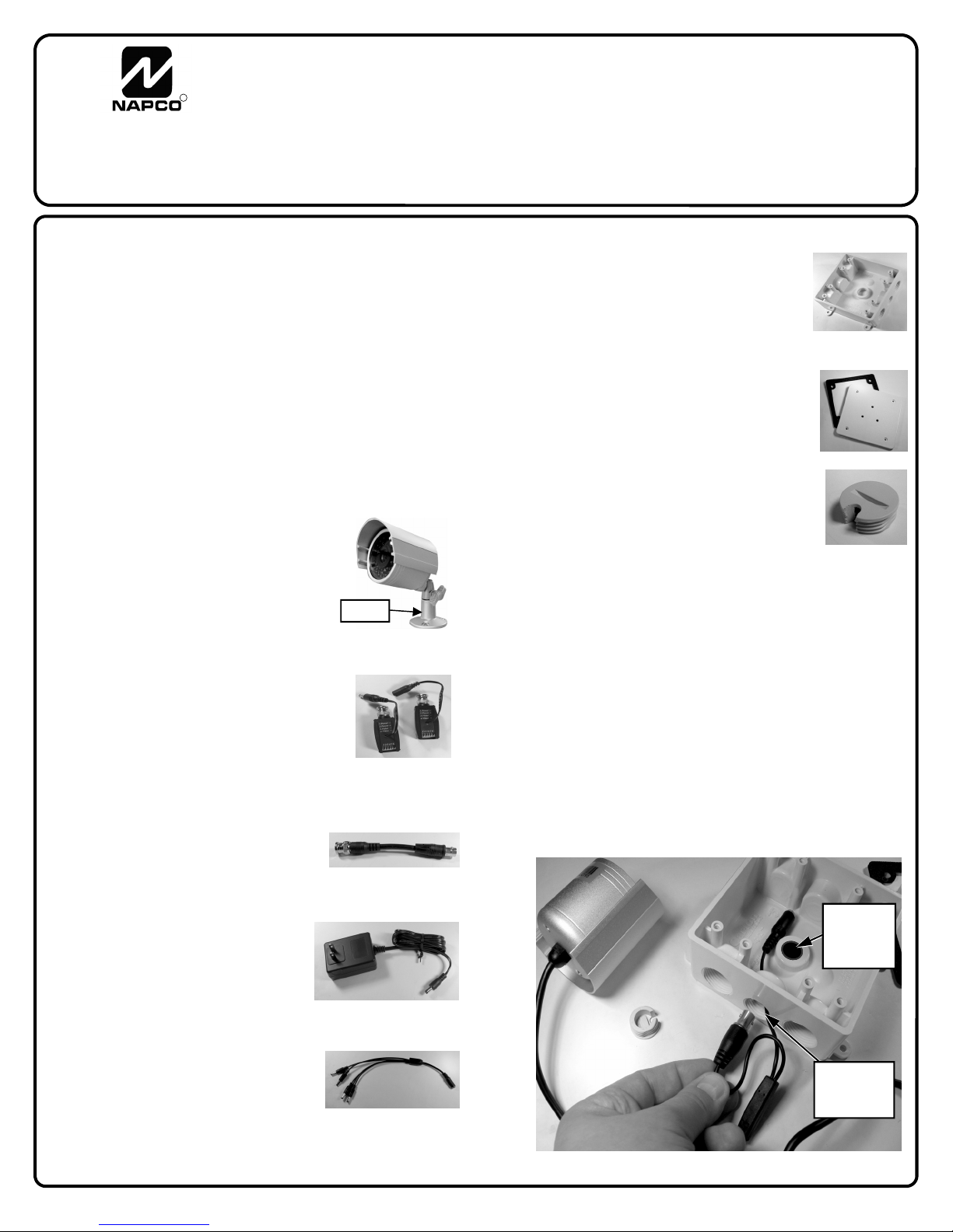
SYSTEM COMPONENTS
ISEE-CAMIR24 IR Bullet style camera,
24 IR LEDs, 50' IR range, 1/4"
Color CCD image sensor, 3.6mm /
f2.0 Standard Lens, 12VDC Operation.
ISEE-VBALUN-P1 Passive Video Balun
allows video and power transmission over CAT5 cable, 6 push pin
terminals. Set of (1) male and (1)
female with 2.1mm CCTV power
lead connectors
ISEE-BNC P-CBL Patch Cable, BNC Male to Female,
RG59, 120mm (for connecting
ISEE-VBALUN-P1 Video Balun
to VIP-Gateway)
ISEE -TRF12VDC2A Plug in style
power transformer/adapter,
provides regulated 12VDC @
2,000mA output with 2.1mm
male connector.
ISEE-PWR1-4 Power Splitter,
CCTV, 1 Female to 4 Male
2.1mm. Provides power to up to
(4) cameras when using ISEE TRF12VDC2A power supply
(Base)
PVC double gang style weatherproof enclo-
sure, white, provides a watertight enclosure for wiring and allows the camera
to be easily and quickly mounted outdoors.
PVC double gang weatherproof cover with
gasket, prepped for mounting of camera
base, white.
PVC plug for sealing of wire entry hole, white,
is slotted to allow the camera cable to
exit the enclosure.
INSTALLATION
The PVC camera mounting / wiring enclosure system allows the camera to be easily and quickly installed on the
side of a building or under an eave. Before wiring the en-
closure, attach the camera mounting bracket base to the
enclosure cover using the three supplied mounting nuts and
bolts.
1. Pull the CAT5 wire through the wall or eave to the location where the camera is to be installed. Punch through
the knock-out on the bottom of the enclosure and one
1/2 inch threaded knock-out on the side. Push the
camera signal and power connectors (one at a time)
through the 1/2 inch threaded hole on the side of the
enclosure.
Knockout
for CAT5
cable
Threaded
hole plug
Note: The product images shown in this manual may be slightly different from the actual product.
Fig. 1: Route the camera wires into enclosure
1
Page 2
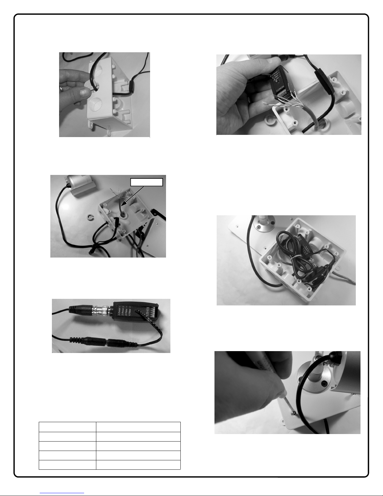
2. Pull an appropriate length of camera cable through the
side entry hole and secure the opening with the PVC
mounting plug. Place the notch on the plug over the
cable and screw into place.
Fig. 2: Install wire plug into enclosure
3. Pull the CAT5 cable through the wire entry hole on the
bottom of the enclosure.
CAT 5 Cable
Fig. 3: Route CAT 5 Cable into base
4. Connect the camera power lead to the video balun with
the male power jack and attach the camera signal lead
to the video balun.
Fig. 4: Secure cover to enclosure
5. Connect the ISEE-VBALUN-P1 Video Balun to CAT5.
Select one pair of CAT5 conductors to be used for
video signal and the remaining 2 or 3 pair to be used to
provide power to the camera. Refer to the following
table to determine the number of CAT5 power conductors required, which is dependent on the length of the
CAT5 cable run.
Length of Wire Run No. of CAT5 Pair Required
125 Feet 3 Pair
100 Feet 3 Pair
75 Feet 2 Pair
50 Feet 2 Pair
6. Connect the CAT5 cable to the ISEE-VBALUN-P1
Video Balun by pushing in the pin-push terminals and
sliding the stripped conductors into the terminal opening.
Fig. 5: Connect CAT5 conductors to video balun
7. After all connections are secure, tie up excess wires
and place wire and balun inside enclosure as shown in
Fig. 6.
Note: To ensure high-quality electrical connections in
outdoor installations, a packet of dielectric grease is
included in the kit. Place a small amount on the BNC
center conductor as well as each stripped CAT5 conductor before making the connections to the balun.
Fig. 6: Place cable and balun into enclosure
8. Affix gasket to cover and secure cover to enclosure with
four (4) screws (supplied) as shown in Fig. 7.
Fig. 7: Secure cover to enclosure
9. The camera enclosure can be mounted on a wall (see
Fig. 8) or a ceiling (see Fig. 9). If mounting on a wall,
2
Page 3

be sure to mount the enclosure with the threaded hole
plug positioned down to create a drainage hole should
any moisture enter the enclosure. In addition, allow a
short length of the camera cable to exit the enclosure
creating a short loop as shown in Fig. 8.
Mounting Tabs
Fig. 8: Create loop when wall mounting
The camera may also be mounted under an eave or on
a ceiling as shown in figure 9.
Fig. 9: Eave or Ceiling mounting
10. Power Supply Connections
The ISEE-QC2CAMKIT includes the ISEE-TRF12 VDC2A
power supply (shown below), which provides a regulated
12VDC at 2 Amps. This power may be distributed to the
cameras using the enclosed ISEE-PWR1-4 Power Splitter.
Simply connect the splitter to the power supply power lead
Fig. 10: ISEE-TRF12VDC2A Transformer / Adapter
and then connect each of the splitter power leads to the
female power plug of the video balun (see Fig. 12).
Fig. 11: ISEE-PWR1-4 Power Splitter
11. Video Balun / Gateway Connections
After connecting the video balun to the power supply splitter cable and making the required CAT5 power and signal
connections, the balun may be connected to the gateway
using the supplied short BNC patch cable.
When all power and signal connections are completed and
the baluns are connected to the gateway (see Fig. 13), the
power supply may be plugged into a wall socket.
Fig. 12: Video baluns connected to the power splitter
Fig. 13: Video balun connected to gateway using
the BNC patch cable.
3
Page 4

NAPCO LIMITED WARRANTY
NAPCO SECURITY SYSTEMS, INC. (NAPCO)
warrants its products to be free from manufacturing
defects in materials and workmanship for thirty-six
months following the date of manufacture. NAPCO will,
within said period, at its option, repair or replace any
product failing to operate correctly without charge to the
original purchaser or user.
This warranty shall not apply to any equipment, or any
part thereof, which has been repaired by others,
improperly installed, improperly used, abused, altered,
damaged, subjected to acts of God, or on which any
serial numbers have been altered, defaced or removed.
Seller will not be responsible for any dismantling or
reinstallation charges.
THERE ARE NO WARRANTIES, EXPRESS OR
IMPLIED, WHICH EXTEND BEYOND THE
DESCRIPTION ON THE FACE HEREOF. THERE IS
NO EXPRESS OR IMPLIED WARRANTY OF
MERCHANTABILITY OR A WARRANTY OF FITNESS
FOR A PARTICULAR PURPOSE. ADDITIONALLY,
THIS WARRANTY IS IN LIEU OF ALL OTHER
OBLIGATIONS OR LIABILITIES ON THE PART OF
NAPCO.
Any action for breach of warranty, including but not
limited to any implied warranty of merchantability, must
be brought within the six months following the end of the
warranty period.
IN NO CASE SHALL NAPCO BE LIABLE TO ANYONE
FOR ANY CONSEQUENTIAL OR INCIDENTAL
DAMAGES FOR BREACH OF THIS OR ANY OTHER
WARRANTY, EXPRESS OR IMPLIED, EVEN IF THE
LOSS OR DAMAGE IS CAUSED BY THE SELLER'S
OWN NEGLIGENCE OR FAULT.
In case of defect, contact the security professional who
installed and maintains your security system. In order to
exercise the warranty, the product must be returned by
the security professional, shipping costs prepaid and
insured to NAPCO. After repair or replacement, NAPCO
assumes the cost of returning products under warranty.
NAPCO shall have no obligation under this warranty, or
otherwise, if the product has been repaired by others,
improperly installed, improperly used, abused, altered,
damaged, subjected to accident, nuisance, flood, fire or
acts of God, or on which any serial numbers have been
altered, defaced or removed. NAPCO will not be
responsible for any dismantling, reassembly or
reinstallation charges.
This warranty contains the entire warranty. It is the sole
warranty and any prior agreements or representations,
whether oral or written, are either merged herein or are
expressly cancelled. NAPCO neither assumes, nor
authorizes any other person purporting to act on its
behalf to modify, to change, or to assume for it, any
other warranty or liability concerning its products.
In no event shall NAPCO be liable for an amount in
excess of NAPCO's original selling price of the product,
for any loss or damage, whether direct, indirect,
incidental, consequential, or otherwise arising out of any
failure of the product. Seller's warranty, as hereinabove
set forth, shall not be enlarged, diminished or affected
by and no obligation or liability shall arise or grow out of
Seller's rendering of technical advice or service in
connection with Buyer's order of the goods furnished
hereunder.
NAPCO RECOMMENDS THAT THE ENTIRE SYSTEM
BE COMPLETELY TESTED WEEKLY.
Warning: Despite frequent testing, and due to, but not
limited to, any or all of the following; criminal tampering,
electrical or communications disruption, it is possible for
the system to fail to perform as expected. NAPCO does
not represent that the product/system may not be
compromised or circumvented; or that the product or
system will prevent any personal injury or property loss
by burglary, robbery, fire or otherwise; nor that the
product or system will in all cases provide adequate
warning or protection. A properly installed and
maintained alarm may only reduce risk of burglary,
robbery, fire or otherwise but it is not insurance or a
guarantee that these events will not occur.
CONSEQUENTLY, SELLER SHALL HAVE NO
LIABILITY FOR ANY PERSONAL INJURY,
PROPERTY DAMAGE, OR OTHER LOSS BASED ON
A CLAIM THE PRODUCT FAILED TO GIVE
WARNING. Therefore, the installer should in turn advise
the consumer to take any and all precautions for his or
her safety including, but not limited to, fleeing the
premises and calling police or fire department, in order
to mitigate the possibilities of harm and/or damage.
NAPCO is not an insurer of either the property or safety
of the user's family or employees, and limits its liability
for any loss or damage including incidental or
consequential damages to NAPCO's original selling
price of the product regardless of the cause of such loss
or damage.
Some states do not allow limitations on how long an
implied warranty lasts or do not allow the exclusion or
limitation of incidental or consequential damages, or
differentiate in their treatment of limitations of liability for
ordinary or gross negligence, so the above limitations or
exclusions may not apply to you. This Warranty gives
you specific legal rights and you may also have other
rights which vary from state to state.
4
 Loading...