

Page 1

PROGRAMMING
R
COMPUTERIZED SECURITY SYSTEM
ARMED
STATUS
SYSTEM ARMED
01/01/97 12:00AM
1243
56
7890
A
B
C
D
E
F
G
NEXT/YES
PRIOR/NO
AREA
GEMINI
ENT A1
R
HARDWIRE
INSTRUCTIONS
WIRELESS
GEM-P1664EX
CONTROL PANEL/COMMUNICATOR
Programming the GEM-P1664EX Control Panel with the
"Classic" GEM-RP2ASe2, GEM-RP3DGTL, and GEM-RP4RFC/GEM-RP4C Keypads and
the
"K Series" GEM-K2AS, GEM-K3DGTL
, and
GEM-K4/GEM-K4RF
Keypads
GEMINI
STATUS
ARMED
R
A
B
C
COMPUTERIZED SECURITY SYSTEM
Quick Start (for GEM-K2AS):
1. Refer to the wiring diagram, connect Siren, Aux. Power,
PGM Output, Remote Bus, Earth Ground, Zone and Telephone Wiring. NOTE: See Installation Instructions (WI1388).
2. Connect AC power first and then the battery.
3. Configure the keypad (see page 55).
4. Access the Easy Menu Driven (Dealer Program) Mode:
Press
456789
Press
NO until “
Press
© NAPCO 2005
NEXT/YES to enter Dealer Program Mode. See page 5.
SYSTEM ARMED
AC ON
01/01/97 12:00AM
1243
56
7890
"K Series" GEM-K2AS
Dealer Code
TURNON PROG Y/N
Publicly traded on NASDAQ Symbol: NSSC
READY
READY
AC ON
NEXT/YES
E
PRIOR/NO
D
F
AREA
G
” appears on the keypad display.
"K Series" GEM-K4/GEM-K4RF
R
R
32
BYPASS FIRE/TBL SYS TBL CHIME
INTER IOR
R
"K Series" GEM-K3DGTL
Quick Start (for GEM-K3DGTL):
1. Refer to the wiring diagram, connect Siren, Aux. Power,
PGM Output, Remote Bus, Earth Ground, Zone and Telephone Wiring. NOTE: See Installation Instructions (WI1388).
2. Connect AC power first and then the battery.
3. Configure the keypad (see page 55).
4. Access the Easy Menu Driven (Dealer Program) Mode:
Press
456789
Press
NO until “17” appears on the keypad display.
Press
NEXT/YES to enter Dealer Program Mode. See page 5.
Dealer Code
R
WI1387 7/05
Page 2

THIS MANUAL INCLUDES FEATURES WHICH ARE ONLY AVAILABLE IN
CONTROL PANEL FIRMWARE VERSION 01 OR LATER.
IMPORTANT NOTE
This manual supports the keypad programming of the GEM-P1664EX control panel with the NAPCO "classic" GEMRP2ASe2, GEM-RP3DGTL and GEM-RP4RFC series keypads as well as the GEM-K2AS, GEM-K3DGTL and GEMK4RF "K Series" keypads. The new "K Series" models offer the new STAY and AWAY buttons with simplified functionality, along with the new MENU and ENTER buttons. While the instructions in this manual are depicted using the "K Series" keypads, the manual applies to both the "classic" and the "K Series" keypads.
Program Mode
The
The
A
button and the U button operate identically (in Program Mode) for both keypads.
D
•
•
is the same for both keypads--
button and the
R
button operate identically (in Program Mode) for both keypads.
only the button names have changed
, as follows:
The
•
"NEXT/YES button" are used in this manual.
button and the button operate identically (in Program Mode) for both keypads. The words
• The
"
PRIOR/NO
For consistency, it is recommended that all keypads either be all "classic" or all "K Series"--both keypad
types should not be used in one alarm system.
button and the button operate identically (in Program Mode) for both keypads. The words
button" are used in this manual.
For direct line to Technical Service, call toll free: (800) 645-9440
NAPCO Security Systems, Inc.
333 Bayview Avenue, Amityville, New York 11701
For Sales and Repairs, call toll free: (800) 645-9445
Internet: http://www.napcosecurity.com
Page 3

WI1387 7/05
TABLE OF CONTENTS
Page 3
SYSTEM PROGRAMMING OPTIONS ...........................................................4
Introduction .............................................................................................4
Downloading From a Computer ...............................................................4
EASY MENU DRIVEN PROGRAM MODE ....................................................5
Dealer Program - Preliminary Information ...............................................5
Accessing Dealer Program Mode ............................................................5
Customizing a Default Program ...............................................................5
GEM-RP2ASe2/GEM-K2AS KEYPAD Easy Program Menu ............6
Total Number of Zones in Area 1 ................................................6
Panel Zone Doubling ...................................................................6
Fire Zones in Area 1 ....................................................................6
2-Wire Fire Zones in Area 1 ........................................................6
Local or Central Station Reporting System .................................6
Exit/Entry Zones in Area 1 ..........................................................6
Interior (Stay) Bypass Zones in Area 1 .......................................7
24 Hour Zones in Area 1 ............................................................7
Chime Zones in Area 1 ..............................................................7
Chime 2 Zones in Area 1 ...........................................................7
Exit/Entry2 Zones in Area 1 .......................................................7
50 mS Loop Response Zones ....................................................7
Aux Output Activated on Alarm Zones .......................................7
Sensor Watch Zones ..................................................................7
Keypad Sounder On Alarm Zones .............................................7
Auto Bypass Re-entry Zones ......................................................8
Enable No EOLR Zones ..............................................................8
Enable Telco Line Fault Test? ....................................................8
Enable Burg Output Chirp on KeyFob? .......................................8
Enable CP1? ...............................................................................8
Number of Keypads in Area 1 .....................................................8
Central Station Receiver 1 Tel. Number ......................................8
Central Station Receiver 1 Account Number ...............................9
Central Station Receiver 1 Format ..............................................9
Enter User Codes .......................................................................9
RF Transmitter Points .................................................................10
Key Fob Transmitters ..................................................................11
Dealer Code ................................................................................11
Clear Program .............................................................................12
Cold Start ....................................................................................12
GEM-RP3DGTL/GEM-K3DGTL and GEM-RP4RFC/GEM-K4RF
KEYPAD Easy Program Menu ........................................................13
Total Number of Zones ...............................................................13
Panel Zone Doubling ..................................................................13
Fire Zones ...................................................................................13
2-Wire Fire Zones .......................................................................13
Local or Central Station Reporting System .................................13
Exit/Entry Zones ..........................................................................13
Interior Zones ..............................................................................14
24 Hour Zones in Area 1 ............................................................14
Chime Zones in Area 1 ..............................................................14
Chime 2 Zones in Area 1 ...........................................................14
Exit/Entry2 Zones in Area 1 .......................................................14
50 mS Loop Response Zones ....................................................14
Aux Output Activated on Alarm Zones .......................................14
Sensor Watch Zones ..................................................................15
Keypad Sounder On Alarm Zones .............................................15
Auto Bypass Re-entry Zones .....................................................15
Enable No EOLR Zones .............................................................15
Enable Telco Line Fault Test? ....................................................15
Enable Burg Output Chirp on KeyFob? .......................................15
Enable CP-01? ............................................................................15
Number of Keypads ....................................................................16
Central Station Receiver 1 Tel. Number ......................................16
Central Station Receiver 1 Account Number ...............................16
Central Station Receiver 1 Format ..............................................16
Enter User Codes .......................................................................16
RF Transmitter Points ................................................................ 17
Key Fob Transmitters ................................................................. 18
Dealer Code ............................................................................... 19
Clear Program ............................................................................ 19
DIRECT ADDRESS PROGRAM MODE ....................................................... 20
Keypad Programming Overview ............................................................. 20
Accessing Direct Address Program Mode .............................................. 20
Keypad Address Program Mode Display ................................................ 21
Direct Address Program Mode Keypad Commands ............................... 21
Direct Address Programming Example ................................................... 22
Conventions Used in this Manual ........................................................... 23
SYSTEM DELAYS & TIMEOUTS ........................................................... 24
SYSTEM OUTPUT TIMEOUTS .............................................................. 25
DOWNLOAD/CALLBACK OPTIONS ..................................................... 25
PAGER FORMAT OPTIONS .................................................................. 25
SYSTEM OPTIONS ............................................................................... 26
GLOBAL AMBUSH CODE ..................................................................... 26
SYSTEM OPTIONS ................................................................................ 27
SYSTEM OPTIONS ................................................................................ 28
CS RECEIVER OPTIONS ...................................................................... 30
CS SUBSCRIBER ID OPTIONS ............................................................ 31
CS SYSTEM REPORTING OPTIONS .................................................... 32
CS AREA & SYSTEM REPORTING OPTIONS ..................................... 32
ZONE ANDING TIME WINDOW ........................................................... 33
KEYPAD UNBLANKING TIME WINDOW ............................................... 33
CLOCK ADJUSTMENTS ........................................................................ 33
CS ZONE REPORTING OPTIONS ........................................................ 34
PULSE EVENT CODE .......................................................................... 34
CS USER REPORTING OPTIONS ........................................................ 35
EZM GROUP OPTIONS ......................................................................... 37
AREA BELL CONTROL OPTIONS ........................................................ 38
KEYPAD OPTIONS ................................................................................ 42
TEMPERATURE DISPLAY AT KEYPAD ............................................... 43
AREA ARMING OPTIONS ..................................................................... 44
ZONE INTEGRATION TIME .................................................................. 44
ZONE OPTIONS - ZONES 1 TO 16 ....................................................... 45
ZONE OPTIONS - ZONES 17 TO 32 ..................................................... 46
ZONE OPTIONS - ZONES 33 TO 48 .................................................... 47
ZONE OPTIONS - ZONES 49 TO 64 .................................................... 48
EXTERNAL RELAY CONTROL ............................................................ 49
RF RECEIVER & SUPERVISORY TIMER OPTIONS ........................... 52
CLEAR PROGRAM OPTIONS ............................................................... 53
USER PROGRAM MODE ............................................................................. 53
Preliminary Information ........................................................................... 53
Accessing User Program Mode .............................................................. 53
User Codes ............................................................................................ 54
KEYPAD CONFIGURATION MODE ............................................................ 55
Keypad Installation ................................................................................. 55
Configuring the Keypads ........................................................................ 55
ALPHABETICAL INDEX .............................................................................. 56
ADDRESS NUMBER LOCATION INDEX ..................................................... 61
GEM-P1664EX WIRING DIAGRAM .............................................................. 64
Refer to accompanying GEM-P1664EX Installation Instructions (WI1388) for installation information.
NOTE: THESE PROGRAMMING INSTRUCTIONS ARE INTENDED AND WRITTEN FOR THE PROFESSIONAL INSTALLER HAVING SUITABLE
EXPERIENCE AND INSTALLATION EQUIPMENT. THE UNIT IS DESIGNED TO BE PROGRAMMED USING AN IBM-COMPATIBLE
COMPUTER WITH NAPCO PCD-WINDOWS SOFTWARE. AFTER PROGRAMMING, BE SURE TO RUN THE PCD-WINDOWS ERROR-CHECK
UTILITY TO GUARD AGAINST PROGRAMMING CONFLICTS FOR THE TYPE OF SERVICE SELECTED FOR THE INSTALLATION.
L
NAPCO Security Systems
GEM-P1664EX Programming Instructions
X
Page 4

Page 4
WI1387 7/05
SYSTEM PROGRAMMING OPTIONS
INTRODUCTION
The GEM-P1664EX control panel may be programmed by various means, each of which will be covered in detail in the
sections that follow. Keypad displays shown are for a GEM-K2AS, GEM-K3DGTL and GEM-K4RF series keypads. With
the GEM-RP2ASe2 and GEM-K2AS keypads, because of their reduced display capabilities, messages are abbreviated
and will scroll through two or more screens. Zone descriptions cannot be programmed using GEM-K2AS or GEMRP2ASe2 keypad, therefore a GEM-RP1CAe2/GEM-K1CA must be used (see WI1386).
Downloading From a Computer. This is the preferred method of programming. The panel may be downloaded
from (or uploaded to) an IBM PC-compatible computer, either locally or remotely. Napco's PCD-Windows
Quickloader software features context-sensitive help screens as well as an error-checking utility that prevents
programming of incompatible or conflicting data to ensure proper panel operation.
Easy Menu-Driven Program (Dealer Program) Mode - Keypad Programming. The Easy Menu-Driven
Program Mode allows keypad programming of number of zones in area 1, panel zone doubling, number of fire
zones (both 4-wire and 2-wire), local or Central Station reporting, number of exit/entry zones, number of interior
zones, number of 24 hour zones, number of chime zones, Chime 2 zones, Exit/Entry2 zones, 50ms loop response
zones, aux output activated on alarm zones, sensor watch zones, keypad sounder on alarm zones, auto bypass
re-entry zones, EOLR zones, number of keypads in area 1, Central Station telephone number, Central Station account number, Central Station receiver format, User Codes, RF transmitter points, RF keyfob transmitters, zone
descriptions, dealer code, Telco line fault test, Burg output chirp on keyfob, enable CP-01, and clear dealer program/cold start. For new panels, a custom default program may be created at the keypad. A menu-driven utility
prompts the installer to configure the system. Further detailed customization is accomplished in the Direct
Address Program Mode.
Direct Address (Dealer Program) Program Mode - Keypad Programming.
is an extension of the Dealer Program Mode wherein data is entered at the keypad by specific location. This mode
is accessed from the Easy Menu Driven Program Mode by pressing the
User Program Mode - Keypad programming.
limited to keypad programming of User Codes.
DOWNLOADING FROM A COMPUTER
The control-panel program may be downloaded from the computer by any of the following methods.
Local Downloading
(Note: This procedure should be used after installation, after peripheral devices are connected).
For direct high-speed data transfer to the control panel from a desktop computer, connect the download jack (JP2)
on the panel to the LOCAL jack (J3) on the Napco PCI2000/3000 computer interface using the supplied 6-
System Programming Options
conductor cable. (Refer to PCI2000/3000 Installation Instructions WI443 for wiring diagram and procedures).
Similarly, a high-speed local download may be made in the field using a notebook or laptop computer. Connect
JP2 on the control panel to a Napco PCI-MINI computer interface using the 6-conductor cable supplied. (Refer to
PCI-MINI Installation Instructions WI767).
Remote Downloading
(Also see PCI2000/3000 Installation Instructions WI443).
Function Mode.
Start by establishing a Telco connection between the computer operator and the installer. During this procedure,
voice contact will be lost, therefore both the installer and the computer operator should be familiar with the
operation. When a steady high-pitched tone is heard at the site phone, access the “ACTIVATE DOWNLOAD” Function
(see Keypad Programming Modes), then press the
up the phone and wait for a call from the central station confirming a successful download.
Callback Method.
An installed, unattended panel may be programmed or reprogrammed remotely using the Callback-Method
Download feature of the PCD Windows software. Remote downloading requires a modem compatible with the
PCI2000/3000. Upon answering the call from the computer, the panel will verify the Download Security Code and,
if confirmed, will establish a connection. If a Callback Number is programmed into the panel, the panel will
automatically disconnect and call the computer at this number before establishing a connection.
The User Program Mode is intended for authorized users and is
button or the YES button; the site phone will go dead. Hang
U
C
The Direct Address Program Mode
button at any time.
GEM-P1664EX Programming Instructions
X
L
NAPCO Security Systems
Page 5

WI1387 7/05
Page 5
EASY MENU DRIVEN PROGRAM MODE
DEALER PROGRAM - PRELIMINARY INFORMATION
The Default Dealer Code is 4
program a custom Dealer Code, which replaces the Default Dealer Code. If you clear your Dealer Code, use the Default Dealer
Code once again to enter programming.
5 6 7 8 9. Use this code to enter the Dealer Program Mode to
After entering codes or data, press the save U button.
If the keypad is in the Program Mode and no activity is detected for longer than 4 minutes, a steady tone will sound.
Silence the sounder by the G button to continue, or by pressing the C button to exit.
A panel that has been COLD STARTED (Address Location 2286) performs identically to a new panel.
When programming a Multiple Area System, Direct Address Programming Mode must be used to complete the program.
Data will not be stored into memory unless U is pressed
ACCESSING DEALER PROGRAM MODE
1. Press
2. Press "PRIOR/NO" button until “TURNON PROG Y/N” (GEM-RP2ASe2/
3. Press "NEXT/YES" button to Enter Dealer Program Mode.
4. Press
456789 R
Dealer Code (Default = 456789)
GEM-K2AS) or “17” (GEM-RP3DGTL/GEM-K3DGTL or
GEM-RP4RFC/GEM-K4RF) appears on the LCD screen.
CC
to exit Dealer Program Mode when finished.
.
Easy Menu Driven Program Mode
CUSTOMIZING A DEFAULT PROGRAM
For new panels, you can design a default program that will best suit your application. Using this procedure, you will configure the panel for:
•
Number of Zones in Area 1
•
Panel Zone Doubling
•
Fire Zones in Area 1
•
2-Wire Fire Zones in Area 1
•
Local or Central Station Reporting System
•
Exit/Entry Zones in Area 1
•
Interior Zones in Area 1
•
24 Hour Zones in Area 1
•
Chime Zones in Area 1
•
Chime 2 Zones in Area 1
•
Exit/Entry2 Zones in Area 1
This procedure will automatically set up system keypads, EZMs, wireless transmitters, etc. After your basic default program has
been loaded, you may alter it as necessary in the Direct Address Program Mode.
NEW PANELS:
means, the number zones will be suppressed and cannot be changed. Should it be necessary to create a new custom default
program, (a) from the Dealer Program Mode, press the
2285 (Clear Program); (c) press the
L
The custom default program may be created for new panels only. Once the panel has been programmed by any
U
NAPCO Security Systems
•
50mS Loop Response Zones
•
Aux Output Activated on Alarm Zones
•
Sensor Watch Zones
•
Keypad Sounder on Alarm Zones
•
Auto Bypass re-entry Zones
•
Enable no EOLR Zones
•
Enable Telco Line Fault Test
•
Enable Burg Output Chirp on Keyfob
•
Enable CP-01
•
Number of Keypads in Area 1
•
Central Station Receiver 1 Tel. Number
C
button and start over.
button to enter the Direct Address Program Mode; (b) access Location
GEM-P1664EX Programming Instructions
X
•
Central Station Receiver 1 Account Number
•
Central Station Receiver 1 Format
•
Enter User Codes
•
RF Transmitter Points
Quick Enroll Method
•
•
Key Fob Transmitters
•
Enter Zone Descriptions
•
Dealer Code
•
Test Timer
Page 6

Page 6
WI1387 7/05
GEM-RP2ASe2/GEM-K2AS Keypad Easy Program Menu
GEMINI
SYSTEM ARMED
STATUS
ARMED
A
B
C
COMPUTERIZED SECURITY SYSTEM
NOTE:
ENT A1
01/01/97 12:00AM
1243
D
56
7890
(Direct Entry)
If you are programming a 2, 3 or 4 Area system, enter the total number of zones required for Areas 1-4. The Direct Address
Program Mode can then be used to remove zones from Area 1 and place them in the other areas. See Zone Options. If
Programming a Wireless-Only system, or using Wireless-Only on Zones 9-64, enter the total number of zones in system. Enter the
transmitter points in the RF Transmitter section of the Easy Menu Driven Programming Mode.
(Press YES or NO)
(Direct Entry)
(Direct Entry)
GEM-RP2ASe2/GEM-K2AS--Easy Menu Driven Program Mode
(Press YES or NO)
(Direct Entry)
Enter the Dealer Security Code (default = 456789) for a new panel or enter your custom Dealer Program Code if
ENT A1
programmed. Press the PRIOR/NO button repeatedly until “
NEXT/YES
E
PRIOR/NO
F
AREA
G
Ent A1
”, you can scroll back by pressing
PROG
each of the following steps, press R to jump to the next screen, the NEXT/YES button to go forwards, the
R
PRIOR/NO button to go backwards,
Total Number of Zones in Area 1
B. Press the NEXT/YES button to enter the Dealer Program Mode. In
to save and C twice to exit at any time.
U
(Appears for New Panel Only)
Directly enter the total number of zones to be programmed for Area 1. Valid entries are from 01 to 64.
TURNON/PROG
” is displayed.
NOTE:
If you pass “
Directly enter the total number of zones, including leading zeros. Use number buttons
#ZnXX
9.
Press 0 for a zero. The system is based on groups of 4 zones each (after the first 8
NOTE:
zones), and will automatically round up to the next group of 4. For example, if you enter 18, it will
automatically convert this to 20 zones. Press U to save. Press the NEXT/YES button to proceed.
Zn Dbl
Panel Zone Doubling
If the total number of zones in Area 1 entered was 16 or greater, press the NEXT/YES button to
(Appears for New Panel Only)
effectively double the capacity of the control panel's hard wired zones from 8 to 16. The 16 zones will re-
Enabl?
Y/N
Ent Fr
Zn#XX
main EOL terminated zones, but will be designated for Normally Closed devices only. The terminal for
Zone 1 will now support Zones 1 and 9 with the use of the supplied EZ Zone Doubling
TM
resistors, E & Z
supplied. (Refer to Wiring Diagram and Installation Instructions). If Panel Zone doubling is not desired,
press the PRIOR/NO button.
Fire Zones in Area 1
(Appears for New Panel Only)
Enter the zone number of any zones which are to be used as Fire Zones (both 2-wire, 4-wire or wireless).
Valid entries are from 01 to 64. Directly enter each zone number, including leading zeros, and press
to save, and then repeat for any additional zone(s). Press NEXT/YES button to proceed.
If you are programming a multiple Area system, enter all the zone numbers required for Areas 1
NOTE:
through 4. The Direct Address Program Mode can then be used to remove zones from Area 1 and place
them in the other areas. See Zone Options.
Ent2WF
2-Wire Fire Zones in Area 1
Enter the zone numbers of any Fire Zones (from previous question) which are to be used with 2-wire
(Appears for New Panel Only)
smoke detectors. The only valid entries are 07 and 08. Directly enter each zone number, including
Zn#XX
leading zeros. Press U to save, and then repeat for any additional zone(s).
Only zones which
NOTE:
have been designated as Fire Zones in the prior question may be programmed as 2 Wire Fire zones.
Report
Press the NEXT/YES button to proceed.
(refer to Installation Instructions).
Local or Central Station Reporting System
Press the NEXT/YES button for all zones to report; press the PRIOR/NO button for no zones to report
JP3 must be set to “2-WF” position for 2-wire fire zones
NOTE:
(Appears for New Panel Only)
(LOCAL SYSTEM).
all Zn
Y/N
EntEE1
Exit/Entry Zones in Area 1
(Appears for New Panel Only)
Directly enter the zone number of any zones which are to be used as Exit/Entry zones. Valid entries are
from 01 to 64. Directly enter each zone number, including leading zeros. Use number buttons
Zn#XX
through
9
.
NOTE:
Press the
button for a zero. Press
0
to save and then repeat for any
U
additional zone(s). Press the NEXT/YES button to proceed.
Chime will automatically be programmed for all E/E zones. If you are programming a multiple
NOTE:
area system, enter all exit/entry zone numbers required for Areas 1-4. The Direct Address Program Mode
can then be used to remove zone from Area 1 and place them in Areas 2, 3 or 4. See Zone Options.
1
1
TURNON/
through
U
GEM-P1664EX Programming Instructions
X
L
NAPCO Security Systems
Page 7

WI1387 7/05
Page 7
EntFol
Zn#XX
(Direct Entry)
number of zones required for Areas 1-4. The Direct Address Program Mode can then be used to remove zones from Area 1 and place them in
Areas 2, 3 or 4. See Zone Options.
Ent24H
Zn#XX
(Direct Entry)
EntCZ1
Zn#XX
(Direct Entry)
EntCZ2
Zn#XX
(Direct Entry)
Interior (Stay) Bypass Zones in Area 1
Directly enter the zone number of any zones which are to be used as Interior Follower Zones. Valid entries are
from 01 to 64. Directly enter each zone number, including leading zeros. Use number buttons 1 through
9.
NEXT/YES button to proceed.
Entry Follower” and "Power Up Delay" zones. If you are programming a multiple Area system, enter the total
24 Hour Zones in Area 1
•
•
•
Chime Zones in Area 1 (New Program Only)
•
•
•
NOTE:
Chime 2 Zones in Area 1 (New Program Only)
•
•
•
NOTE: A chime time of 2 seconds will be automatically programmed.
Chime 2 zones give a distinct pulsating tone when zone is faulted.
NOTE: Press 0 for a zero. Press
NOTE:
(New Program Only)
Enter the zone numbers of zones to be used as 24 Hour zones.
Valid entries are from 01 to 64. Directly enter each zone number, including leading zeros.
Press U to save and repeat for any additional zone(s); press the NEXT/YES button to proceed.
Enter the zone numbers which are to be used as Chime Zones.
Valid entries are from 01 to 64. Directly enter each zone number, including leading zeros.
Press U to save and then repeat for any additional zone(s), press the NEXT/YES button to proceed.
A chime time of 2 seconds will be automatically programmed.
Enter the zone numbers which are to be used as Chime 2 Zones.
Valid entries are from 01 to 64. Directly enter each zone number, including leading zeros.
Press U to save and then repeat for any additional zone(s), Press the NEXT/YES button to proceed.
(Appears for New Panel Only)
to save and then repeat for any additional zone(s). Press the
U
All Interior Follower zones will also be automatically programmed as “Exit/
EntEE2
Zn#XX
(Direct Entry)
Ent50m
Zn#XX
(Direct Entry)
EntAux
Zn#XX
(Direct Entry)
Ent SW
Zn#XX
(Direct Entry)
EntKPS
Zn#XX
(Direct Entry)
Exit/Entry2 Zones in Area 1 (New Program Only)
Enter the zone numbers of zones to be used as Exit/Entry 2 zones.
•
Valid entries are from 01 to 64. Directly enter each zone number, including leading zeros.
•
Press U to save and repeat for any additional zone(s); press the NEXT/YES button to proceed.
•
NOTE: An Exit/Entry 2 Entry Time of 30 sec. will automatically be programmed.
50 mS Loop Response Zones
Enter the zone numbers of zones to be have a 50mS loop response. Note: Time can also be adjusted
•
via address 2280.
Valid entries are from 01 to 08. Directly enter each zone number, including leading zeros.
•
Press U to save and then repeat for any additional zone(s), Press the NEXT/YES button to proceed.
•
AUX Output Activated on Alarm Zones
Enter the zone numbers of zones to activate the PGM2 output upon alarm.
•
Valid entries are from 01 to 64. Directly enter each zone number, including leading zeros.
•
Press U to save and then repeat for any additional zone(s), Press the NEXT/YES button to proceed.
•
An Aux Output Timeout of 15 Minutes will automatically be programmed.
NOTE:
Sensor Watch Zones (New Program Only)
Enter the zone numbers of zones to be Sensor Watch zones.
•
Valid entries are from 01 to 64. Directly enter each zone number, including leading zeros.
•
Press U to save and then repeat for any additional zone(s), Press the NEXT/YES button to proceed.
•
NOTE: A Sensor Watch Time of 24 hours will automatically be programmed.
Keypad Sounder On Alarm Zones (New Program Only)
Enter the zone numbers of all zones to activate the Keypad Sounder upon alarm.
•
Valid entries are from 01 to 64. Directly enter each zone number, including leading zeros.
•
Press U to save and then repeat for any additional zone(s), press the NEXT/YES button to proceed.
•
(New Program Only)
(New Program Only)
GEM-RP2ASe2/GEM-K2AS--Easy Menu Driven Program Mode
L
NAPCO Security Systems
GEM-P1664EX Programming Instructions
X
Page 8

Page 8
WI1387 7/05
EntAUB
Zn#XX
(Direct Entry)
EnNEOL
Y/N
(Press YES or NO)
Telco
Ln Fit
Y/N
(Press YES or NO)
KF Out
Chirp
Y/N
(Press YES or NO)
Enable
CP01?
Y/N
(Press YES or NO)
Ent A1
#KP 01
(Direct Entry)
GEM-RP2ASe2/GEM-K2AS--Easy Menu Driven Program Mode
Phone#
______
______
(Direct Entry)
Auto Bypass Re-entry Zones (New Program Only)
Enter the zone numbers of zones to be Auto Bypass Re-entry zones.
•
Valid entries are from 01 to 64. Directly enter each zone number, including leading zeros.
•
Press U to save and then repeat for any additional zone(s), press the NEXT/YES button to proceed.
•
•
Auto Bypass Re-entry Zones allow the system to be armed with the zone faulted but come back into the
system (armed) when the zone is subsequently secured.
Enable No EOLR Zones
Press the NEXT/YES button to program all zones except 24 Hr & fire zones for No End Of Line Resis-
•
tor. Press the PRIOR/NO button to continue.
Enable Telco Line Fault Test?
Press the NEXT/YES button to enable Telco Line Fault Test.
•
Press the PRIOR/NO button to continue.
•
NOTE: If enabled, a Telco Line Fault Test Delay of 60 seconds will automatically be programmed.
Enable Burg Output Chirp on KeyFob?
Press the NEXT/YES button to enable Burg Output Chirp on KeyFob Arm / Disarm.
•
Press the PRIOR/NO button to continue.
•
NOTE: The Burg Output will chirp once on Keyfob Arm and twice on Keyfob Disarm.
Enable SIA CP01? (New Program Only)
Press the NEXT/YES button to enable.
•
Press the PRIOR/NO button to continue.
•
The SIA CP-01 Features are designed to reduce the incidence of false alarms. See WI1388, "Installer Programming Quick Reference Chart SIA False Alarm Reduction" and "GEM-P1664 Factory Default Description"
for more information. NOTE: Do not enable unless reporting, otherwise system trouble Fail to Communi-
cate may occur.
Number of Keypads in Area 1
Directly enter the total number of Keypads to be installed in Area 1. Valid entries are from 01 to 07. Directly
enter the number of keypads, including leading zeros. Use number buttons 1 through 9. NOTE:
Press
keypads can only be assigned in Direct Address Programming. See Keypad Options.
Central Station Receiver 1 Telephone Number
Using number buttons, enter telephone number of up to 16 digits including prefix letters, if necessary, for
receiver 1. Use number buttons
G 1 through G 5
and
Detection = “E”. Pressing
ton to proceed.
NOTE:
Programming. See CS Receiver Options.
for a zero. Press U to save. Press the NEXT/YES button to proceed.
0
Central Station Receiver 2 and 3 Telephone Numbers can only be entered in Direct Address
(New Program Only)
(New Program Only)
(New Program Only)
through
1
will produce a blank space (•). Press U to save. Press the NEXT/YES but-
0
9
for letters B–F, respectively. NOTE: Pre-Dial Delay = “D”; Dial-Tone
for digits 1–9; press the
NOTE:
G 0
Area 2, 3 or 4
buttons for a zero
GEM-P1664EX Programming Instructions
X
L
NAPCO Security Systems
Page 9

WI1387 7/05
(Direct Entry)
(Direct Entry)
(Direct Entry)
(Direct Entry)
(Direct Entry)
Acc #
(____)
RecFmt
( )
User01
______
OPT__
ACC __
Page 9
Central Station Receiver 1 Account Number
Enter an account number of up to four digits. Use number buttons
Press the
G 0
buttons for a zero and press
for a blank space (•). Press U to save. Press the
0
1
through 9 for digits 1–9. NOTE:
NEXT/YES button to proceed.
NOTE:
Central Station Receiver 2-4 Account Numbers can only be entered in Direct Address Programming.
See CS Reporting Options.
Central Station Receiver 1 Format
From the table below, enter the central station's receiver format. Use number buttons
NOTE: Press the
through
G 4
G 0 buttons for a zero and press 0 for a blank space (•). Press G 1
for letters B–E, respectively. Press U to save. Press the NEXT/YES button to
1
through
9
proceed.
NOTE: Central Station Receiver 2 and 3 Formats can only be entered in Direct Address Programming. See
CS Receiver Options.
DATA ENTRY CS RECEIVER 1 FORMAT
•(blank) Ademco Slow, Silent Knight Slow
2 Radionics Fast
3 Silent Knight Fast
4 Radionics, DCI, Franklin Slow
DATA ENTRY CS RECEIVER 1 FORMAT
5 Universal High Speed
B SIA
C Ademco Point ID
E Pager
Enter User Codes (Press the (
R) button to set cursor.)
For default program, enter up to 64 User Codes, with Area 1-4 Options.
Press
once to set the cursor to the User Code. Use the number buttons
R
1
through
9
to
enter a code from 3 to 6 digits. Enter up to 6 digits (4 digits is recommended) in the first six boxes from
left to right for each user code. Valid entries are: 0-9. NOTE: Press
G0
for a blank space (•). No blank spaces in between; leave blank (•) any trailing boxes. If
for a zero and press
0
“Enable Global Ambush Code” (Address 0720) is enabled and “Global Ambush Code” (Address 1054) is
left blank(•), do not program the first two digits of ANY User Code the same as the “Global Ambush
not
Code”.
Note:
If the programmed code was less than 6 digits, press
Options Level (OPT). Refer to the table on the next page for the available area options.
to set the cursor to the Area 1
R
Note:
Duplicate
User Codes are not allowed; therefore a duplicate Code entered in the LCD Window will erase when U is
pressed.
GEM-RP2ASe2/GEM-K2AS--Easy Menu Driven Program Mode
.
L
NAPCO Security Systems
GEM-P1664EX Programming Instructions
X
Page 10

Page 10
WI1387 7/05
USER CODE
(UP TO 6 DIGITS)
AREA OPTIONS EXPLANATION
Disabled User Code not active in this area.
Arm/Di sarm Allows User Code to arm/disarm this area.
Arm Onl y Prevents User Code from disarming this area.
Service A Service Code has restrict ed arm/disarm rights; if an area is armed with a
Access This is normally used to activate a door strike while an area is disarmed. Also
Ambush
* User Program User Program Option is enabled for Keypad 1 only, w herever it is connected (Area
Bypass Enable Security Bypass--Bypass is enabled only with a security code.
USER OPTIONS
AREA 1
AREA 2
OPTIONS
AREA 3
OPTIONS
MONITOR ON
OPTIONS
Service Code, a “
can be disarmed with any valid User Code, including a Service Cod e. If the area is
armed with OTHER than a Service Code, it CANNOT be disarmed w ith a Service
Code. This is typically used to allow tradesmen access to premises under control
of the owner.
program “Access Control on PGM2 Output” (Address 0719) and “PGM2 Output
Access Control Timeout” (Address 0711).
There are two types of Ambush Codes: (1) A 2-digit code (prefix) that is entered
immediately prior to (and as part of) the regular User Code and (2) A separate and
unique User Code. Disarming with an Ambush Code will cause a silent report to be
sent to a central station. Thus, should a user be forced to disarm, he can silently signal
an emergency while appearing to be merely disarming the system.
1 or Area 2). To enable User Program Option for any user add 8 to the data entry
for Area 1 Option (see example). Then, User Programming can be performed only
at Keypad 1 by a user code with user program enabled.
AREA 4
OPTIONS
” appears on the GEM-RP2ASe2 keypad and the area
USER AREA OPTIONS
DATA ENTRIES
L R
blank(•) blank(•) Disabled
blank(•) 1 Arm/Disarm
blank(•) 2 Arm Only
blank(•) 3 Service
blank(•) 4 Access
blank(•) 5 Ambush
blank(•) Add 8 * User Program
4 blank(•) Bypass Enable
OPTION
ENABLED
AREA OPTIONS: Area 1-4 Options may be
programmed for all 64 users.
Select the desired Area Options (Area 1-4)
from the table shown and enter in the
remaining four boxes for each user code.
Example:
area 1 options of “Arm/Disarm” and “User Program”.
Enter “2222” for a user code, “•(blank) 9” for area 1
options and “•(blank) •(blank)” for area 2 options.
For Area 2-4 Options (ACC), press
Program a code of “2222” for user 02, with
A
again. Refer to the table above for available
options.
NOTE:
Press U to save. To proceed to the next User
Press
for blank space (•).
0
Code, press R to set the cursor to the User
Number and change it using the number buttons.
Program a new User Code as previously described.
Remember to record your user codes in the Easy
Menu Programming Worksheet at the back of this
manual.
Related User Options: “Enable Global Ambush
Code” (Address 1422), “Global Ambush Code” (Address
2045) & “Enable Manager's Mode” (Address 1421).
CHANGING OR CANCELING A CODE:
to save. Similarly, to cancel a code, blank out each number of the code press
U
To change any code, merely program over the existing code as described above and press
Zn# 01
RF Transmitter Points (Press the (
(For wireless systems only. Also see Quick Method, which follows)
For each transmitter (key fob transmitters also), enter the zone number (01–64) to which the transmitter
000000
will be mapped, the
6-digit RF ID #:1-digit checksum number
point number (1–2); enter “9” for unsupervised (all points). NOTE: When programming the ID Code
(Direct Entry)
:0 Pt
(Direct Entry)
Quick Enroll Method
number, “0” through ”9” =
G 2
; “D” =
G 3
save. Press the NEXT/YES button button to proceed.
.
If a receiver is already installed in the panel, Napco transmitter
wireless points can be programmed automatically (“enrolled”)
using the following procedure. NOTE: The transmitter point will
GEM-RP2ASe2/GEM-K2AS--Easy Menu Driven Program Mode
be enrolled only if the signal strength is 3 or greater.
1. Enter the zone number to which the transmitter point will be
mapped.
2. Press the
button to enter the Enroll Mode. The red and
B
green LEDs on the keypad will flash.
3. Open the loop of the point that is to be programmed (GEMTRANS2 only).
4. Install the transmitter battery. The keypad will beep to indicate
that the point has been successfully enrolled. Multi-point
transmitters can be mapped to successive zones
simultaneously (see example).
to save.
U
R
) button to set cursor.)
printed on the transmitter and box, the
0 through 9; “A” = G 0; “B” = G 1; “C” =
; “E” =
G 4
Example.
and “F” =
A 2-point transmitter has the RF ID number 287613:1.
G 5
. Press U to
Map point 1 to Zone 6 and point 2 to Zone 9.
1. Enter the Enroll mode as described above.
2. Enter Zone “06”.
3. Open point-1 loop.
4. Install the battery. The keypad will beep once to indicate that
one point has been programmed. (Transmitter 287613:1, point
1 will be mapped to Zone 6).
5. Enter Zone “09”.
6. Close point-1 loop and open point-2 loop.
7. Remove the transmitter battery, then re-install it. The keypad
will beep once to indicate that one point has been
programmed. (Transmitter 287613:1, point 2 is mapped to
Zone 9).
GEM-P1664EX Programming Instructions
X
L
NAPCO Security Systems
Page 11

WI1387 7/05
KEY FOB ZONE ASSIGNMENT: Key fobs can also be assigned to zones to allow multiple wireless panic buttons on one alarm
system, each reporting to a central station, a pager or having a description on the keypad that describes the person holding the key
fob, the location where the person holding the key fob is stationed, or the special purpose of the key fob button being depressed.
See Key Fob Transmitters as Zone Input Devices .
KFob01
Area
(Direct Entry)
000000
(Direct Entry)
:0 0 0
(Direct Entry)
9, respectively; “A” = G 0; “B” = G 1; “C” = G 2
G 3.
If the Key Fob is converted for Two Button “Emergency Use” (by cutting an internal jumper), both top
or bottom buttons must be depressed to activate an alarm. In this case, the Aux-1 and Aux-2
cannot be programmed. Press
Key Fob Transmitters as Zone Input Devices
(refer to display as shown above: press the PRIOR/NO button to go backwards).
Each of the 4 key fob buttons can be assigned to a zone. For example, On button = point 1; Off button = point 2; A1 = point 3; A2 =
point 4. Up to 64 key fobs (using 1 button) or 32 key fobs (using 2 buttons) or 16 key fobs (using all 4 buttons) or any combination up
to a maximum of 64 controlled zones can be assigned, providing multiple wireless panic buttons on a system, each reporting to a
Central Station or a pager and/or annunciating on a keypad the key fob zone number with description/location. To assign a key fob to
a zone: program the keyfob as you would a transmitter, entering the keyfob's ID code, check sum and point number at the appropriate
zone. The “Quick Method” is not allowed. The zone may be hardwired to an electrical sensor as well as assigned to a key fob (either
one will activate the zone alarm output). NOTE: If assigning a key fob to a zone, the “ON/OFF” buttons on the key fob will no longer
arm/disarm the system. The key fob is converted to a “panic only” device.
ZONE DESCRIPTIONS: GEM-RP2ASe2 cannot be used to enter Zone Descriptions. To enter Zone Descriptions, you must use the
GEM-RP1CAe2 Keypad / GEM-K1CA Keypad (See WI1386) or the Napco PCD-Windows Quickloader Software.
Key Fob Transmitters as Arm/Disarm & Control Devices
(Press
Keyfobs can be programmed as “Arm/Disarm” devices using their On/Off buttons (refer to WI752). For
each Key Fob Transmitter, enter:
The Key Fob Transmitter number (01–08). Press 01 through 0
Area number to which transmitter is assigned (0 to disable keyfob, 1 - 4). Press
2
The 6-digit RF ID # printed on the transmitter (enter all numbers and/or letters, including leading “0”s,
if any): “0” through ”9” =
2
1-digit checksum number printed on the transmitter.
Aux 1 Option
Aux 2 Option (see key fob aux 1 & aux 2 options).
For Aux 1/Aux 2 Options: “0”, “1”, “2” and ”9” =
to set cursor).
R
for 0, 1 and 2, respectively.
through
0
; “D” =
G 3
(see key fob aux 1 & aux 2 options).
to save. Press the NEXT/YES button to proceed.
U
; “E” =
G 4
; “A” =
9
and “F” =
0, 1, 2
G 0
G 5
and “D” =
; “B” =
.
and
8
G 1
DATA
ENTRY
0 None
1 Relay Group 1 Toggle
2 Relay Group 2 Toggle
9 Keypad Panic
A Keypad Aux.
B Instant
C PGM2 Ouput Toggle
D Access on PGM2 Output
E Arm Stay
F Interior Button
Page 11
for 01-08.
0, 1 and
; “C” =
AUX 1/AUX 2
OPTIONS
G
GEM-RP2ASe2/GEM-K2AS--Easy Menu Driven Program Mode
D Code
(Direct Entry)
456789
(Direct Entry)
Dealer Code
Directly enter the Dealer Code (default = 456789), including leading zeros. Use the 1 through 9
buttons. NOTE: Press 0 for a zero. Press U to save. Re-enter the Dealer Code to verify the
previous code. Press
RE-ENT
(Direct Entry)
L
NAPCO Security Systems
to save. Press the NEXT/YES button to proceed.
U
GEM-P1664EX Programming Instructions
X
Page 12

Page 12
EXIT DEALER PROGRAM MODE: This completes the custom default program. Press the
Address Program Mode for further programming or press
operation.
once again to end all programming and resume normal keypad
C
C
button to enter the Direct
WI1387 7/05
CLEAR PROGRAM:
to enter the Address Program Mode; (b) access Location 2285 (Clear Program) or 2286 (Cold Start); (c) press U and then
C
(d) press
keypad.
C
2285 XX
(Direct Entry)
Driven Program Mode to program system again.
2286 XX
(Direct Entry)
(schedules) can only be programmed again with the Downloading Software.
Should it be necessary to create a new custom default program, (a) from the Dealer Program Mode, press
to exit the Dealer Program Mode. A “
Clear Dealer Program (Erases Dealer Program)
This erases the dealer program. Use this feature to start a customized default program. Program
Data and System Status Memory is erased where Scheduled Data and Zone Descriptions are
maintained.
Access address 2285, then press the U button. Data entry is not allowed.
Cold Start (Erases Entire Program)
This erases the entire program including Dealer Program by erasing Program Data, Zone Description
Data and System Status Data (similar to a new panel).
Access address 2286, then press the
SYSTEM TROUBLE/E09-00 SERVICE
button. Data entry is not allowed.
U
” will occur. Press
NOTE:
NOTE:
C
Enter Easy Menu
Some features
to silence the
GEM-RP2ASe2/GEM-K2AS--Easy Menu Driven Program Mode
GEM-P1664EX Programming Instructions
X
L
NAPCO Security Systems
Page 13

WI1387 7/05
R
COMPUTERIZED SECURITY SYSTEM
ARMED
STATUS
SYSTEM ARMED
01/01/97 12:00AM
1243
56
7890
A
B
C
D
E
F
G
NEXT/YES
PRIOR/NO
AREA
GEMINI
ENT A1
17
INTERIOR
BYPASS
FIRE/TBL
SYS TBL
CHIME
Page 13
GEM-RP3DGTL/GEM-K3DGTL and GEM-RP4RFC/GEM-K4RF Keypad Easy Program Menu
your Easy Program Mode responses (before pressing
If the data is correct, press U to save. If the data is incorrect, press R to set the cursor into the next field and again enter your data.
Note: Review your Easy Program Mode responses after the initial programming of the control, except for questions marked "For New Panel
Only". These questions set up the basic structure of the panel program ("Number of Zones in an Area", etc.) and cannot be viewed or altered
once set. To exit the Dealer Program Mode, press
01
H
03
04
H
05
H
06
07
H
INTERIOR
INTERIOR
INTERIOR
INTERIOR
INTERIOR
INTERIOR
Enter the Default Dealer Program Code ("456789") for a new panel or enter your custom Dealer Program Code if
programmed. Press
). Press [NEXT] to enter Dealer Program Mode. For the GEM-RP3DGTL/GEM-K3DGTL (and GEM-RP4RFC/GEM-
B
K4RF), questions are in the form of a 2-digit number flashing in the display. Press
answer the question. Press
Flashing
, followed by [PRIOR/NO] repeatedly until “17” is displayed (you can scroll back by pressing
R
to set the cursor into the next field to
R
R again to scroll through each segment. Press [NEXT] to go to the next question. To review
to save), press
U
until the 2-digit question number flashes in the display again.
R
C twice to resume normal keypad operation. To return the panel to the factory default,
enter the Direct Address Program Mode, go to location 2286 and press
U
Total Number of Zones (Appears for New Panel Only)
Directly enter the total number of zones to be programmed. Valid entries are from 01 to 64. Directly
enter the total number of zones, including leading zeros. Use number buttons
0
NOTE: Press the
button for a zero. The system is based on groups of 4 zones each (after the
first 8 zones), and will automatically round up to the next group of 4. For example, if you enter 13, it will
automatically convert this to 16 zones. Press
to save. Press the NEXT/YES button to proceed.
U
INTERIOR
(Direct Entry)
FIRE/TBL SYS TBL
BYPASS
FIRE/TBL SYS TBL CHIME
BYPASS
CHIME
Panel Zone Doubling (New Program Only)
To double the number of hardwired panel zones from 8 to 16, press the NEXT/YES button.
FIRE/TBL SYS TBL CHIME
BYPASS
(Press YES or NO)
•
If Panel Zone doubling is not desired, press the PRIOR/NO button.
•
The 16 zones will remain EOL terminated zones, requiring Normally Closed devices only.
•
Refer to Wiring Diagram and Installation Instructions for wiring instructions
•
Fire Zones (Appears for New Panel Only)
FIRE/TBL SYS TBL CHIME
BYPASS
Enter the zone number of any Fire Zones (both 2-wire, 4-wire or wireless). Valid entries are from 01 to
64. Directly enter each zone number, including leading zeros, and press
for any additional zone(s). Press the NEXT/YES button to proceed.
INTERIOR
(Direct Entry)
FIRE/TBL SYS TBL CHIME
BYPASS
NOTE: If you are programming a multiple Area system, enter the zone number of zones required for
Areas 1-4. The Direct Address Program Mode can then be used to remove zones from Area 1 and
place them in Areas 2-4. See Zone Options.
2-Wire Fire Zones (Appears for New Panel Only)
Enter the zone number of any Fire Zones (from previous question) which are to be used with 2-wire
FIRE/TBL SYS TBL CHIME
INTERIOR
(Direct Entry)
BYPASS
FIRE/TBL SYS TBL CHIME
BYPASS
smoke detectors. The only valid entries are 07 and 08. Directly enter each zone number, including
leading zeros. Press
to save, and then repeat for any additional zone.
U
have been designated as Fire Zones can be programmed as 2 Wire Fire zones. Press the NEXT/YES
button to proceed.
Installation Instructions).
JP7 must be set to “2-WF” position for 2-wire fire zones 7 and 8 (refer to
NOTE:
Local System or C.S. Reporting System (Appears for New Panel Only)
Press the NEXT/YES button for all zones to report; press the PRIOR/NO button for no zones to report
FIRE/TBL SYS TBL CHIME
BYPASS
(Press YES or NO)
(LOCAL SYSTEM).
Exit/Entry Zones (Appears for New Panel Only)
Directly enter the zone numbers which are to be used as Exit/Entry zones. Valid entries are from 01 to
FIRE/TBL SYS TBL CHIME
INTERIOR
(Direct Entry)
BYPASS
BYPASS
FIRE/TBL SYS TBL
CHIME
64. Directly enter each zone number, including leading zeros. Use number buttons
. NOTE: Press the
9
button for a zero. Press U to save and then repeat for any additional
0
zone(s). Press the NEXT/YES button to proceed.
NOTE: Exit/Entry Zones will have an entry delay of 30 seconds and an exit delay of 60 seconds.
.
1
through 9.
to save, and then repeat
U
Only zones which
NOTE:
1
through
GEM-RP3DGTL/GEM-K3DGTL AND GEM-RP4RFC/GEM-K4RF Easy Menu Driven Program Mode
L
NAPCO Security Systems
GEM-P1664EX Programming Instructions
X
Page 14

GEM-RP3DGTL/GEM-K3DGTL AND GEM-RP4RFC/GEM-K4RF Easy Menu Driven Program Mode
Page 14
08
H
09
H
10
H
11
H
12
H
13
H
14
H
INTERIOR
INTERIOR
(Direct Entry)
INTERIOR
INTERIOR
(Direct Entry)
INTERIOR
INTERIOR
(Direct Entry)
INTERIOR
INTERIOR
(Direct Entry)
INTERIOR
INTERIOR
(Direct Entry)
INTERIOR
INTERIOR
(Direct Entry)
INTERIOR
INTERIOR
(Direct Entry)
FIRE/TBL SYS TBL
BYPASS
FIRE/TBL SYS TBL
BYPASS
FIRE/TBL SYS TBL
BYPASS
FIRE/TBL SYS TBL
BYPASS
FIRE/TBL SYS TBL CHIME
BYPASS
FIRE/TBL SYS TBL CHIME
BYPASS
FIRE/TBL SYS TBL CHIME
BYPASS
FIRE/TBL SYS TBL CHIME
BYPASS
FIRE/TBL SYS TBL CHIME
BYPASS
FIRE/TBL SYS TBL
BYPASS
FIRE/TBL SYS TBL CHIME
BYPASS
FIRE/TBL SYS TBL
BYPASS
FIRE/TBL SYS TBL
BYPASS
FIRE/TBL SYS TBL CHIME
BYPASS
WI1387 7/05
Interior Zones (Appears for New Panel Only)
Directly enter the zone numbers which are to be used as Interior Zones. Valid entries are from 01 to
CHIME
64. Directly enter each zone number, including leading zeros. Use number buttons
9. NOTE: Press the 0
additional zone(s). Press the NEXT/YES button to proceed.
CHIME
NOTE:
"Power Up Delay" zones.
24 Hour Zones in Area 1
•
CHIME
•
•
CHIME
All Interior zones will also be automatically programmed as “Exit/Entry Follower” and
(New Program Only)
Enter the zone numbers of zones to be used as 24 Hour zones.
Valid entries are from 01 to 64. Directly enter each zone number, including leading zeros.
Press U to save and repeat for any additional zone(s); press the NEXT/YES button to proceed.
Chime Zones in Area 1 (New Program Only)
Enter the zone numbers which are to be used as Chime Zones.
•
Valid entries are from 01 to 64. Directly enter each zone number, including leading zeros.
•
Press U to save and then repeat for any additional zone(s), press the NEXT/YES button to proceed.
•
NOTE: A chime time of 2 seconds will be automatically programmed.
Chime 2 Zones in Area 1
Enter the zone numbers which are to be used as Chime 2 Zones.
•
Valid entries are from 01 to 64. Directly enter each zone number, including leading zeros.
•
Press U to save and then repeat for any additional zone(s), Press the NEXT/YES button to proceed.
•
A chime time of 2 seconds will be automatically programmed.
NOTE:
Chime 2 zones give a distinct pulsating tone when zone is faulted.
(New Program Only)
Exit/Entry2 Zones in Area 1 (New Program Only)
Enter the zone numbers of zones to be used as Exit/Entry zones.
•
Valid entries are from 01 to 64. Directly enter each zone number, including leading zeros.
•
Press U to save and repeat for any additional zone(s); press the NEXT/YES button to proceed.
•
An Exit/Entry 2 Entry Time of 30 sec. will automatically be programmed.
NOTE:
CHIME
50 mS Loop Response Zones (New Program Only)
Enter the zone numbers of zones to be have a 50mS loop response.
•
Valid entries are from 01 to 8. Directly enter each zone number, including leading zeros.
•
Press U to save and then repeat for any additional zone(s), press the NEXT/YES button to pro-
•
ceed. Note: Time can also be adjusted via address 2280.
CHIME
Aux Output Activated on Alarm Zones (New Program Only)
Enter the zone numbers of zones to activate the PGM2 Output upon alarm.
•
CHIME
Valid entries are from 01 to 64. Directly enter each zone number, including leading zeros.
•
Press U to save and then repeat for any additional zone(s), Press the NEXT/YES button to pro-
•
ceed.
NOTE: A PGM2 Output Timeout of 15 Minutes will automatically be programmed.
button for a zero. Press U to save and then repeat for any
1
through
GEM-P1664EX Programming Instructions
X
L
NAPCO Security Systems
Page 15

WI1387 7/05
15
H
16
H
17
H
18
19
20
21
INTERIOR
INTERIOR
INTERIOR
INTERIOR
INTERIOR
INTERIOR
INTERIOR
(Press YES or NO)
INTERIOR
(Press YES or NO)
INTERIOR
(Press YES or NO)
INTERIOR
(Press YES or NO)
FIRE/TBL SYS TBL CHIME
BYPASS
FIRE/TBL SYS TBL CHIME
BYPASS
(Direct Entry)
FIRE/TBL SYS TBL
BYPASS
FIRE/TBL SYS TBL
BYPASS
(Direct Entry)
FIRE/TBL SYS TBL
BYPASS
FIRE/TBL SYS TBL CHIME
BYPASS
(Direct Entry)
FIRE/TBL SYS TBL CHIME
BYPASS
FIRE/TBL SYS TBL CHIME
BYPASS
FIRE/TBL SYS TBL
BYPASS
FIRE/TBL SYS TBL
BYPASS
Sensor Watch Zones (New Program Only)
Enter the zone numbers of zones to be Sensor Watch zones.
•
Valid entries are from 01 to 64. Directly enter each zone number, including leading zeros.
•
Press U to save and then repeat for any additional zone(s), press the NEXT/YES button to proceed.
•
NOTE: A Sensor Watch Time of 24 hours will automatically be programmed.
Keypad Sounder On Alarm Zones
Enter the zone numbers of all zones to activate the Keypad Sounder upon alarm.
•
CHIME
CHIME
Valid entries are from 01 to 64. Directly enter each zone number, including leading zeros.
•
Press U to save and then repeat for any additional zone(s), press the NEXT/YES button to proceed.
•
(New Program Only)
Auto Bypass Re-entry Zones (New Program Only)
Enter the zone numbers of zones to be Auto Bypass Re-entry zones.
•
CHIME
Valid entries are from 01 to 64. Directly enter each zone number, including leading zeros.
•
Press U to save and then repeat for any additional zone(s), press the NEXT/YES button to proceed.
•
Auto Bypass Re-entry Zones allow the system to be armed with the zone faulted but come back
•
into the system (armed) when the zone is subsequently closed.
Enable No EOLR Zones
Press the NEXT/YES button to program all zones except 24 Hr & fire zones for No End Of Line
•
(New Program Only)
Resistor. Press the PRIOR/NO button to continue.
Enable Telco Line Fault Test?
Press the NEXT/YES button to enable Telco Line Fault Test.
•
Press the PRIOR/NO button to continue.
•
NOTE: There is a preset 60 second Telco Line Fault Test Delay.
Enable Burg Output Chirp on KeyFob?
Press the NEXT/YES button to enable Burg Output Chirp on KeyFob Arm / Disarm.
•
Press the PRIOR/NO button to continue.
•
CHIME
NOTE: The Burg Output will chirp once on Keyfob Arm and twice on Keyfob Disarm.
Enable SIA CP-01?
Press the NEXT/YES button to enable.
•
Press the PRIOR/NO button to continue.
•
CHIME
The SIA CP-01 Features are designed to reduce the incidence of false alarms. NOTE: Do not
enable unless reporting, otherwise system trouble Fail to Communicate may occur.
Page 15
GEM-RP3DGTL/GEM-K3DGTL AND GEM-RP4RFC/GEM-K4RF Easy Menu Driven Program Mode
L
NAPCO Security Systems
GEM-P1664EX Programming Instructions
X
Page 16

Page 16
Number of Keypads
22
_ H
INTERIOR
INTERIOR
BYPASS
BYPASS
FIRE/TBL SYS TBL
FIRE/TBL SYS TBL
CHIME
CHIME
Directly enter the total number of Keypads to be installed. Valid entries are from 01 to 07. Directly
enter the number of keypads, including leading zeros. Use number buttons
NOTE:
Press
for a zero. Press U to save. Press the NEXT/YES button to proceed.
0
(Direct Entry)
Central Station Receiver 1 Telephone Number
24
_ 3
INTERIOR
INTERIOR
FIRE/TBL SYS TBL CHIME
BYPASS
FIRE/TBL SYS TBL
BYPASS
(Direct Entry)
CHIME
Using number buttons, enter telephone number of up to 16 digits including prefix letters, if
necessary, for receiver 1. Use number buttons 1 through 9 for digits 1–9; press G
0
for a zero and G
1
through G
5 for letters B–F, respectively. NOTE:
Pre-Dial Delay = “D”; Dial-Tone Detection = “E”. Pressing
Press
to save. Press the NEXT/YES button to proceed. NOTE: Central Station Receiver 2 and
U
3 Telephone Numbers can only be entered in Direct Address Programming. See CS Receiver
Options.
Central Station Receiver 1 Account Number
25
_ 3
INTERIOR
INTERIOR
FIRE/TBL SYS TBL
BYPASS
FIRE/TBL SYS TBL
BYPASS
(Direct Entry)
CHIME
CHIME
Enter an account number of up to four digits. Use number buttons
0
1–9. NOTE: Press the
space (•). Press
to save. Press the NEXT/YES button to proceed. NOTE: Central Station
U
button for a zero and press the G
Receiver 2 and 3 Account Numbers can only be entered in Direct Address Programming. See CS
Reporting Options.
Central Station Receiver 1 Format
26
INTERIOR
8
INTERIOR
DATA ENTRY CS RECEIVER 1 FORMAT
blank(•) Ademco Slow, Silent Knight Slow
1 Sescoa, Vertex, DCI, Franklin Fast
2 Radionics Fast
3 Silent Knight Fast
4 Radionics, DCI, Franklin Slow
5 Universal High Speed
8 Radionics BFSK
FIRE/TBL SYS TBL CHIME
BYPASS
FIRE/TBL SYS TBL
BYPASS
(Direct Entry)
CHIME
From the table below, enter the central station's receiver format. Use number buttons
through 9. NOTE: Press the 0 button for a zero and press G
space (•). Press
G 1
through
G 4
for letters B–E, respectively. Press U to
save. Press the NEXT/YES button to proceed.
DATA ENTRY CS RECEIVER 1 FORMAT
9 FBI 4/3/1
0 Radionics Modem 2
B SIA
C Ademco Point ID
D Ademco Express
E Pager
) button to set cursor)
R
27
INTERIOR
INTERIOR
(Direct Entry)
BYPASS
BYPASS
FIRE/TBL SYS TBL
FIRE/TBL SYS TBL
Enter User Codes (Press the (
Enter up to 64 User Codes with User Options for each code. Refer to the tables below for available
CHIME
data entries for User Options.
Press R once to set cursor to the User Number and enter the desired User Number. Press
once again to set the cursor to the User Code. Use the number buttons
R
CHIME
enter a code from 3 to 6 digits. Enter up to 6 digits (4 digits are recommended) in the first six boxes
from left to right for each user code. Valid entries are: 0-9. Note: Press
spaces in between; leave blank (•) any trailing boxes. If an “Ambush Prefix” (Address 0495) is entered,
do not program the first two digits of ANY User Code as the same digits entered for the “Ambush Prefix”.
WI1387 7/05
through
1
0 will produce a blank space (•).
1 through 9 for digits
0 buttons for a blank
0
for a blank
NOTE: Modem IIe is available
only in Direct Address
Programming. Central Station
Receiver 2 and 3 Formats can
only be entered in Direct
Address Programming. See
CS Receiver Options.
through
1
0 for a zero. No blank
9
9
1
.
to
If the programmed code is less than 6 digits, press R to set the cursor to USER OPTIONS.
Refer to the tables on the next page for the available User Option data entries.
GEM-RP3DGTL/GEM-K3DGTL AND GEM-RP4RFC/GEM-K4RF Easy Menu Driven Program Mode
GEM-P1664EX Programming Instructions
X
L
NAPCO Security Systems
Page 17

WI1387 7/05
Page 17
USER CODE
(UP TO 6 DIGITS)
CODE TYPE EXPLANATION
Disabled User Code not active.
Arm/Disarm Allows User Code to arm/disarm.
Arm Only P revents User Code from disarming.
Service A Ser vice Code has restricted arm /disarm rights; if an area is ar med with a Ser vice Code,
Access This is normally used to activate a door strike. Also program “Access Control on PGM2
Ambush There are two types of Ambush Codes: (1) A 2-digit code (prefix) that is entered
* User Program User Program Option is enabled for Keypad 1 only, wherever it is connected. To enable
Bypass Enable Security Bypass--Bypass is enabled only with a security code.
Related User Options: “Enable Global Ambush Code” (Address 1422) & “Global
Ambush Code” (Address 2045).
USER OPTIONS
AREA 1
AREA 2
AREA 3
OPTIONS
OPTIONS
SERVICE ON
a “
any valid User Code, including a Service Code. If the area is armed with OTHER than a
Service Code, it CANNOT be disarmed with a Service Code. This is typically used to
allow tradesmen access to premises under control of the owner.
Output” (Address 0719) and “PGM2 Output Access Control Timeout” (Address 0711).
immediately prior to (and as part of) the regular User Code and (2) A separate and
unique User Code. Disarming with an Ambush Code will cause a silent report to be
sent to a central station. Thus, should a user be forced to disarm, he can silently signal
an emergency while appearing to be merely disarming the system.
User Program Option for any user add 8 to the data entry Option (see example). Then,
User Programming can be performed only at Ke ypad 1 by a user c ode with user program
enabled.
” appears on the GEM-RP2ASe2 keypad and the area can be disarmed with
OPTIONS
AREA 4
OPTIONS
USER AREA OPTIONS
DATA ENTRIES
L R
blank(•) blank(•) Disabled
blank(•) 1 Arm/Disarm
blank(•) 2 Arm Only
blank(•) 3 Service
blank(•) 4 Access
blank(•) 5 Ambush
blank(•) Add 8 * User Program
4 blank(•) Bypass Enable
OPTION
ENABLED
USER OPTIONS: Area 1-4 options for 64 Us-
ers:
Select the desired options from the table
shown and enter in the remaining boxes
for each user code.
Example: Program a code of “1234” for user 02,
with Area 1 options of “Arm/Disarm” and “User
Program”:
With “27” displayed in keypad window, press
R, 0 2 (User 2),
1234
(User Code),
0
options),
U
Notes:
00
(save).
(1) For
User Code
for Blank Space; (2) For
0 for Blank Space.
CHANGING OR CANCELING A CODE: To change
any code, merely program over the existing code as
described above and press
cancel a code, blank out each number of the code
and press
not allowed; therefore a duplicate Code entered in the
LCD Window will erase when
to save. Note: Duplicate User Codes are
U
,
G 0 G
09
(User Area 2 Options), and
, press
User Options
U
is pressed.
U
R
(User Area 1
G 0
, press
to save. Similarly, to
GEM-RP3DGTL/GEM-K3DGTL AND GEM-RP4RFC/GEM-K4RF Easy Menu Driven Program Mode
RF Transmitter Points (Press the (
28
INTERIOR
FIRE/TBL SYS TBL CHIME
BYPASS
(For wireless systems only. Also see Quick Method, which follows).
For each transmitter (key fob transmitters also), enter the zone number (01–64) to which the
transmitter will be mapped, the 6-digit RF ID#: 1-digit checksum number printed on the transmitter and
INTERIOR
FIRE/TBL SYS TBL CHIME
BYPASS
box, the point number (1–4); enter “9” for unsupervised (all points).
ID Code number, “A” =
“E” =
G 4
G 0; “B” = G 1; “C” = G 2; “D” = G 3;
; “F” =
G 5
Quick Enroll Method.
If a receiver is already installed in the panel, Napco transmitter
wireless points can be programmed automatically (“enrolled”)
using the following procedure.
be enrolled only if the signal strength is 3 or greater.
1. Enter the zone number to which the transmitter point will be
mapped.
2. Press the
button to enter the Enroll Mode. The red and
B
green LEDs on the keypad will flash and the window will
display as shown at left.
3. Open the loop of the point that is to be programmed (GEMTRANS2 or GEM-TRANS4 only).
4. Install the transmitter battery. The keypad will beep to indicate
that the point has been successfully enrolled. Multi-point
transmitters can be mapped to successive zones
simultaneously (Example 1) or to selected zones point by
point (Example 2).
Example 1.
A 4-point transmitter has the RF ID number
410078:1. Map the first three points to Zones 11–13,
respectively.
1. Enter the Enroll mode as described in step 2 above.
2. Enter Zone “11”.
The transmitter point will
NOTE:
R) button to set cursor)
When programming the
NOTE:
. Press J to save. Press NEXT (
E
) to proceed.
3. Open the loops of points 1, 2 and 3.
4. Install the transmitter battery. The keypad will beep 3 times to
indicate that three points have been programmed.
Transmitter 410078:1, point 1 will be mapped to Zone 11.
Transmitter 410078:1, point 2 will be mapped to Zone 12.
Transmitter 410078:1, point 3 will be mapped to Zone 13.
The keypad will now display Zone 13, the last zone enrolled.
Example 2. A 2-point transmitter has the RF ID number
287613:1. Map point 1 to Zone 6 and point 2 to Zone 9.
1. Enter the Enroll mode as described above.
2. Enter Zone “06”.
3. Open point-1 loop.
4. Install the battery. The keypad will beep once to indicate that
one point has been programmed. (Transmitter 287613:1,
point 1 will be mapped to Zone 6).
5. Enter Zone “09”.
6. Close point-1 loop and open point-2 loop.
7. Remove the transmitter battery, then re-install it. The keypad
will beep once to indicate that one point has been
programmed. (Transmitter 287613:1, point 2 is mapped to
Zone 9).
L
NAPCO Security Systems
GEM-P1664EX Programming Instructions
X
Page 18

Page 18
KEY FOB ZONE ASSIGNMENT:
one alarm system, each reporting to a central station, a pager or having a description on the keypad that describes the
person holding the key fob, the location where the person holding the key fob is stationed, or the special purpose of the
key fob button being depressed. See the next page on key fob Zone Assignment.
29
Press U to save. Press the NEXT/YES button to proceed.
INTERIOR
INTERIOR
leading “0”s, if any).
1-digit checksum number printed on the transmitter (enter all numbers and/or letters, including leading “0”s, if any).
Aux-1 Option (see key fob aux 1 & aux 2 options).
Aux-2 Option (see key fob aux 1 & aux 2 options).
FIRE/TBL SYS TBL CHIME
BYPASS
FIRE/TBL SYS TBL CHIME
BYPASS
Key fobs can also be assigned to zones to allow multiple wireless panic buttons on
Key Fob Transmitters (Press
Keyfobs can be programmed as “Arm/Disarm” devices (refer to WI752).
For each Key Fob Transmitter, enter:
The Key Fob Transmitter number (01–08).
Area number to which transmitter is assigned (1 - 4); enter 0 to disable keyfob.
The 6-digit RF ID # printed on the transmitter (enter all numbers and/or letters, including
R to set cursor).
WI1387 7/05
DATA
ENTRY
0 None
1 Relay Group 1 Toggle
2 Relay Group 2 Toggle
9 Panic
A Auxiliary
B Instant
C PGM2 Output Toggle
D Access on PGM2
E Arm Stay
F Interior Button
controlled zones can be assigned, providing multiple wireless panic buttons on a system, each reporting to the Central Station or a
pager and/or annunciating on a keypad the key fob zone number with description/location. To assign a key fob to a zone:
program the key fob as you would a transmitter, entering the key fob's ID code, check sum and point number at the appropriate
zone. The “Quick Method” is not allowed. The zone may be hardwired to a sensor as well as assigned to a key fob (either one will
activate the zone alarm output). NOTE: If assigning a key fob to a zone, the “ON/OFF” buttons on the key fob will no longer arm/
disarm the system. The key fob is converted to a “panic only” device.
AUX 1/AUX 2
OPTIONS
Output
If the Key Fob is converted for Two Button “Emergency Use” (by cutting an internal
Note:
jumper), both top or bottom buttons must be depressed to activate an alarm. In this case, the
Aux-1 and Aux-2 cannot be programmed.
Key Fob Transmitters as Zone Input Devices (refer to display above: press the PRIOR/NO
button to go backwards).
Each of the 4 key fob buttons can be assigned to a zone. For example, On button = point 1; Off
button = point 2; A1 = point 3; A2 = point 4. Up to 64 key fobs (using 1 button) or 32 key fobs
(using 2 buttons) or 16 key fobs (using all 4 buttons) or any combination up to a maximum of 64
NOTE: Key fobs 1-8 report
openings and closings as
Users 57-64.
GEM-RP3DGTL/GEM-K3DGTL AND GEM-RP4RFC/GEM-K4RF Easy Menu Driven Program Mode
GEM-P1664EX Programming Instructions
X
L
NAPCO Security Systems
Page 19

WI1387 7/05
Page 19
ZONE DESCRIPTIONS: GEM-K3DGTL cannot be used to enter Zone Descriptions. To enter Zone Descriptions, you must use the GEM-K1CA
Keypad or the Napco Quickloader Software.
DATE ENTRY: GEM-K3DGTL cannot be used to enter the date. To enter Date, you must use the GEM-K1CA Keypad (Version 5 or later) or the
Napco Quickloader Software.
TIME ENTRY: GEM-K3DGTL cannot be used to enter the time. To enter Time, you must use the GEM-K1CA Keypad (Version 5 or later) or the
Napco Quickloader Software.
33
INTERIOR
rE
INTERIOR
EXIT DEALER PROGRAM MODE: This completes the custom default program. Press
Program Mode for further programming or press
CLEAR PROGRAM: Should it be necessary to create a new custom default program, (a) from the Dealer Program Mode, press
to enter the Address Program Mode; (b) access Location 2285 (Clear Program) or 2286 (Cold Start); (c) press U and then
C
(d) press
FIRE/TBL SYS TBL CHIME
BYPASS
FIRE/TBL SYS TBL
BYPASS
(Direct Entry)
to exit the Dealer Program Mode. A System Trouble Condition will occur. Press
C
Dealer Code
Directly enter the Dealer Code, including leading zeros. Use the
NOTE: Press
Re-enter the Dealer Code to verify the previous code. Press
CHIME
button to proceed. NOTE: The Dealer Code can be two or more digits (up to 6 digits).
for a zero. Press U to save.
0
once again to end all programming and resume normal keypad operation.
C
1 through 9 buttons.
to save. Press the NEXT/YES
U
to enter the Direct Address
C
C
to silence the keypad.
GEM-RP3DGTL/GEM-K3DGTL AND GEM-RP4RFC/GEM-K4RF Easy Menu Driven Program Mode
L
NAPCO Security Systems
GEM-P1664EX Programming Instructions
X
Page 20

Page 20
WI1387 7/05
DIRECT ADDRESS PROGRAM MODE
This is an extension of the Dealer Program Mode. This method of programming is used in conjunction with the Keypad
Programming Worksheets that follow. Refer to these worksheets to identify the 4-digit location (address) of the feature
to be programmed. An illustrative example is provided on the next page.
ADDRESS
LOCATIONS
LEFT DIGIT RIGHT DIGIT
0000
0000
TO
2287
ACCESSING DIRECT ADDRESS PROGRAM MODE
DATA ENTRY
LOCATIONS
3 C
HEXADECIMAL DATA:
BLANK (•) = No Options
•
•
1 to 9 = Entries 1 to 9
0 = Entry of 10
•
B to F = Entries 11 to 15
•
KEYPAD PROGRAMMING OVERVIEW
Direct Address Programming allows you to go directly to the address
locations and change the data entries to customize your control
panel options. Whereas the Easy Menu Program Mode is a simple
quick start guide with limited options, the Direct Address Program
Mode is more flexible allowing you to change all the options.
It consists of multiple address locations with two data entry locations
each (left and right) as shown in the adjacent diagram.
Direct Address Program Mode
1. Press
EEEEEE
2. Press the PRIOR/NO (
Dealer Security Code
(Default is 456789)
Q
) button until:
R
"TURNON PROG Y/N" (GEM-RP2ASe2/GEM-K2AS)
--or- "17" (GEM-RP3DGTL/GEM-K3DGTL or GEM-RP4RFC/GEM-
K4RF) appears on the keypad display.
3. Press the NEXT/YES (
(The panel and keypad version appears briefly on the keypad display).
4. Press
C
to exit Easy Menu Driven Program Mode & enter
P
) button to enter Dealer Program Mode.
Direct Address Program Mode.
(For keypad display examples when in Program Mode, see next page).
GEM-P1664EX Programming Instructions
X
L
NAPCO Security Systems
Page 21
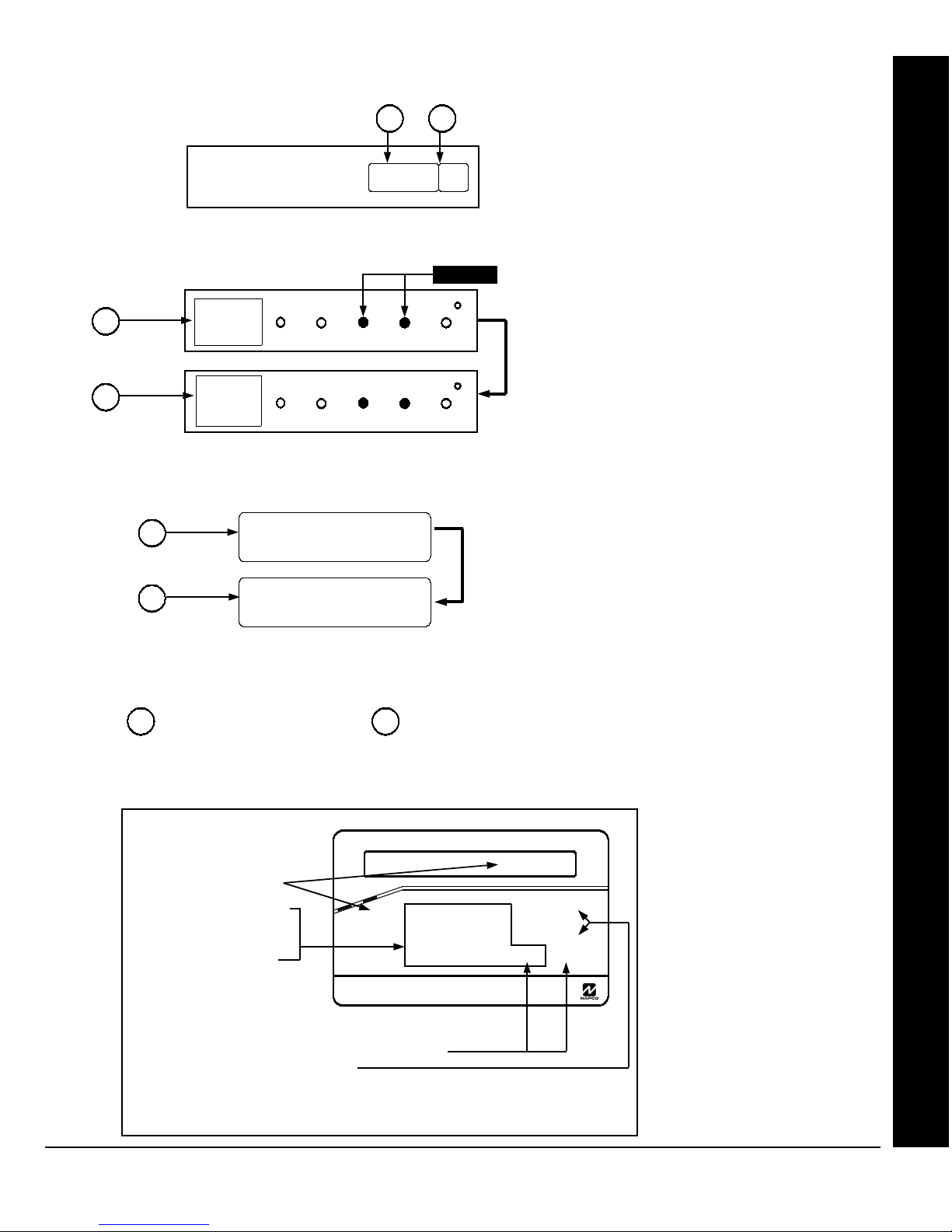
WI1387 7/05
KEYPAD ADDRESS PROGRAM MODE DISPLAY
1
2
1 2
00003C
GEM-RP2ASe2/GEM-K2AS Keypads
(Direct Entry)
3P
3C
GEM-RP3DGTL/GEM-K3DGTL Keypads
1
2
= ADDRESS LOCATION
P
3C
GEM-RP4RFC/GEM-K4RF Keypads
BYPASS FIRE/TBL SYS TBL CH IME
INTERIO R
BYPASS SYS TBL CHIME
INTERIO R
FIRE/TBL
1 2
Flashing
Press
address location, and (2) the corresponding
data shown.
Press R followed by (1) the 4 digit
address location, and (2) the corresponding
data shown.
when in Address Program Mode.
= DATA ENTRY LOCATION (Left and Right Digits)
followed by (1) the 4 digit
R
Note:
A long beep sounds
DIRECT ADDRESS PROGRAM MODE KEYPAD COMMANDS
A. GEM-K2AS (and GEM-RP2ASe2) Keypad
Page 21
Direct Address Program Mode
To access, press C in
Dealer Program Mode
1. Toggle Cursor to 4-digit address field using the
R
button.
2. Enter address Number directly
using number buttons (0-9).
3. Enter Data directly using number buttons.*
4. Press the
button to save.
U
To exit, press
Press
NOTE:
Select NEXT/PRIOR Address.
Press
.
C
button to clear character at cursor.
0
GP
to jump to next programming block.
through
G5
L
* Press
G0
NAPCO Security Systems
GEMINI
STATUS
ARMED
R
1 2
B 4 5 6
C 7 8 9 0
COMPUTERIZED SECURITY SYSTEM
for 10-15, respectively.
00003C
3
NEXT/YES
P
PRIOR/NO
U
Q
AREA
G
GEM-P1664EX Programming Instructions
X
Page 22
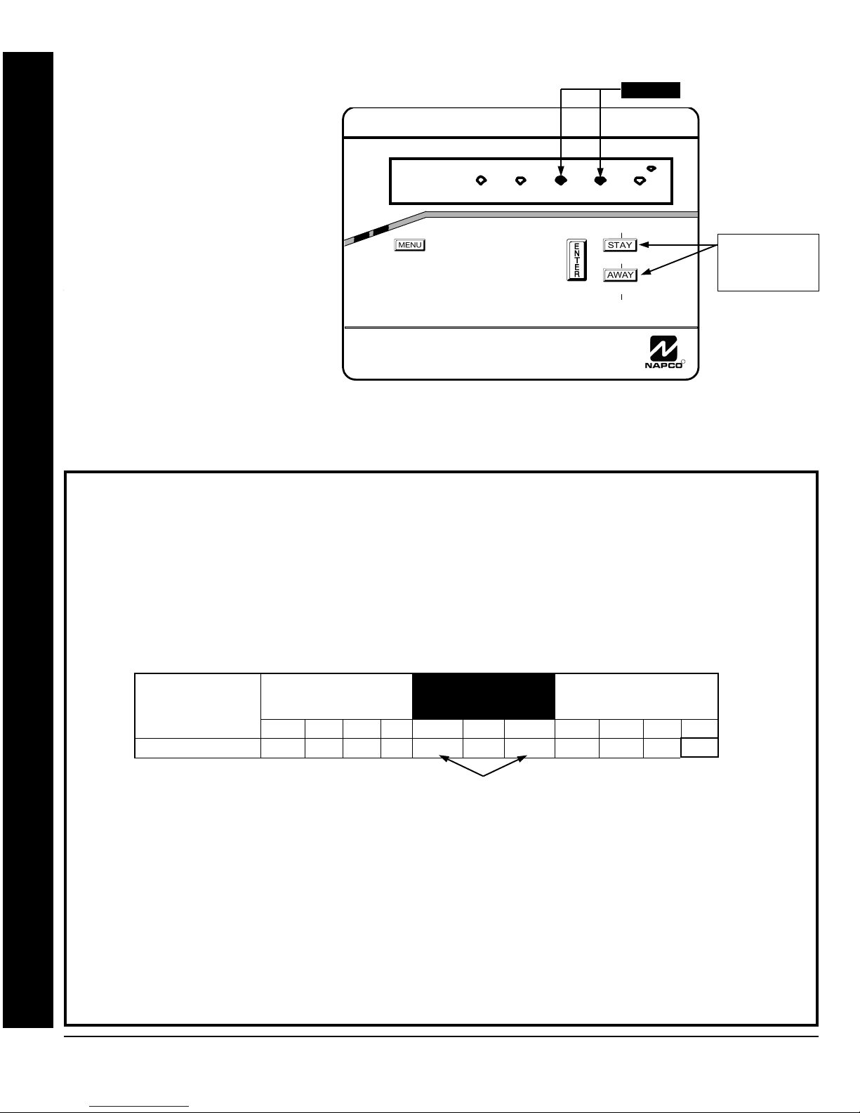
Page 22
R
COMPUTERIZED SECURITY SYSTEM
ARMED
STATUS
SYSTEM ARMED
01/01/97 12:00AM
12
4
3
56
7890
A
B
C
D
E
F
G
NEXT/YES
PRIOR/NO
AREA
GEMINI
ENT A1
3C
INT ERIOR
The displays shown on the previous page will appear after a brief delay.
B. GEM-K3DGTL/GEM-RP3DGTL Keypads
Use the the
To access Direct Address Program
Mode, press
Enter the address directly using the number buttons.
Menu Mode.
The contents of the address will be read automatically, and the cursor will advance to the data field. Enter the
required data directly using the number buttons.
1. Press
Press Jto save the contents of each address.
2. Enter the 4 digit Address location
EXIT DIRECT ADDRESS PROGRAM MODE: When done, press the
PROGRAMMING OVERVIEW
operation. The panel is now programmed with your program.
The Keypad Programming Worksheets in the back are provided as an address-programming reference to help the
installer modify his custom default program or to make minor field alterations to an existing panel program. It is
recommended that the panel be uploaded to Napco's Quickloader software following any keypad programming and that
the PCD3000's error-check feature be utilized to reduce the possibility of programming omissions or conflicts.
Note: Most of the addresses shown comprise two data entry locations, left and right digits. Program the left digits on the
left data-display segment, and the right digit on the right segment. For those addresses having only one programmable
nibble, program the right segment only; the left segment should display a blank (•).
directly using number buttons
(0-9).
3. Enter the 2 digit data directly
using number buttons (0-9).
4. Press U to save.
To exit, press
Keep the Keypad Programming Worksheets on file for future reference.
General Programming Steps
1. Contact the central station to ascertain receiver format, data format, event codes, subscriber numbers and
NOTE:
“F” =
NOTE:
Direct Address Program Mode
“A” =
telephone number(s).
G 5
2. Select the desired features by circling the respective “address” boxes. Refer to the Programming Options and
Worksheets for guidance in selecting the “data” (1,2,4,8) to be entered into those boxes.
Example: Direct Address Programming
3. Program the data entered in the boxes on the worksheets into the respective addresses. The display will show the
Program Zones 6, 7 and 8 as Exit/Entry Follower Zones.
entry numerically, but will display “0” for the number 10, and letters “B”, “C”, “D”, “E”, and “F” for the numbers 11
through 15, respectively. To program a 10, press
DETERMINE THE DATA ENTRIES
through
1. Referring to ZONE FEATURES in the Programming Worksheets that follow, Exit/Entry Follower for Zones 5
See the Direct Address Programming Example on the following page.
through 8 are located at address 0916, left digit. Circle
2. Add the data values for Zones 6, 7 and 8: 2+4+8=14. From Tables 1 and 2, “14” (E) is entered as press
G4. The right digit (for Zones 1 through 4, none of which are Exit/Entry Follower Zones) is entered as
a blank (•).
PROGRAM THE DATA ENTRIES
1. Enter the panel's Dealer Security Code, then press
2. Answer NO (
NOTE:
A
button to toggle the cursor between the 4-digit address field and the data entry locations.
C
R
C
G 0
G 5, respectively.
ZONE OPTION
EXIT/ENTRY FOLLOWER
F
in the Easy
.
.
; “B” =
. Press
G 1
0
for a zero or to clear.
LEFT DATA VALUES
SUM = 14 (CIRCLE
ZN08 ZN07 ZN06 ZN05
& "
) to all questions until “
ZONES
; “C” =
G 2
G 0. To program 11 through 15, press G 1
)
1
R
ACTIVATE PROGRAM Y/N
If you pass “ACTIVATE PROGRAM”, scroll backward using
Flashing
button to exit and resume normal keypad
C
DATA ENTRY SELECTIONS
(BINARY VALUE CIRCLED)
8 4 2 1 blank
8 4 2
8 4
; “D” =
8 4
8
"
8
"
8
"
8
"
4 2 1 8
&
the data values for Zones 5–8.
&
&
&
4 2
4
4
& "
& "
ADDRESS 0916
& "
L ADDR R
& "
E
BLANK (•) 8 4 2
0916
G 3
2 1 4
2
2 1 12
2
ENTRY
TOTAL
0
1
1 2
; “E” =
3
5
1 6
7
9
1 10
11
ZONES
13
RIGHT DATA VALUES
1 14
SUM = 0 (CIRCLE
ZN04 ZN03 ZN02 ZN01
15
1
2
G 4
3
4
5
6
7
8
9
G 0
G 1
G 2
G 3
G 4
G 5
Table 1. Determining data entry for a location (each
“nibble”). Numbers in parentheses indicate data for
ENTER DATA
selected zones or features. (See Programming
.
Worksheets that follow.)
” is displayed; then press the NEXT/YES button.
B.
WI1387 7/05
Press here to
Select NEXT/
PRIOR address
PRESS
N
)
1
KEYPAD
DISPLAYS
;
•
1
2
3
4
5
6
7
8
9
0
B
C
D
E
F
3. Press
4. Press
C
to enter the Address Program Mode. Address "0000" will display.
0916
advance to the data field.
5. Press
6. Press
7. Enter another 4-digit address to continue programming or press
X
G 4 to enter an “E” in the left digit and press 0 to enter a blank (•) in the right digit.
to save. Address 0916 is now programmed with “E •”.
U
GEM-P1664EX Programming Instructions
to access Address 0916. The data for both digits will display and the cursor will
C
to exit and resume normal keypad operation.
L
NAPCO Security Systems
Page 23
)
1
Page 23
KEYPAD
DISPLAYS
•
1
2
3
E
4
5
6
7
8
9
0
B
C
D
E
F
).
WI1387 7/05
The displays shown on the previous pages will appear after a brief delay.
Direct Address Programming Example
Use R to toggle the cursor between the 4-digit address field and the data entry locations.
Example: Program Zones 6, 7 and 8 as Exit/Entry Follower Zones.
Enter the address directly using the number buttons.
DETERMINE THE DATA ENTRIES
The contents of the address will be read automatically, along with the feature name and programming information.
1. Referring to ZONE FEATURES in the Programming Worksheets that follow, Exit/Entry Follower for Zones 5
The cursor will advance to the data field. Enter the required data directly using the number buttons.
through 8 are located at address 0506, left digit. Circle
Press U to save the contents of each address.
2. Add the data values for Zones 6, 7 and 8: 2+4+8=14. From Tables 1 and 2, “14” (E) is entered as press
G4
EXIT DIRECT ADDRESS PROGRAM MODE:
blank (•).
CONVENTIONS USED IN THIS MANUAL
The Keypad Programming Worksheets in the back are provided as an address-programming reference to help the
installer modify his custom default program or to make
minor field alterations to an existing panel program. It is
recommended that the panel be uploaded to NAPCO's
PROGRAM THE DATA ENTRIES
PCD-Windows software following any keypad
1. Enter the panel's Dealer Security Code (Address 0500), then press
programming and that the PCD-Windows error-check
feature be utilized to reduce the possibility of
the A button.
programming omissions or conflicts.
Note:
entry locations, left and right digits. Program the left
digits on the left data-display segment, and the right digit
on the right segment. For those addresses having only
Most of the addresses shown comprise two data
2. Answer NO (
NOTE: If you pass “ACTIVATE PROGRAM”, scroll backward using the the
3. Press the
. The right digit (for Zones 1 through 4, none of which are Exit/Entry Follower Zones) is entered as a
When done, press
ZONES
ZONE OPTION
EXIT/ENTRY FOLLOWER
F
) to all questions until “ACTIVATE PROGRAM Y/N” is displayed; then press YES (
button to enter the Address Program Mode. Address "0000" will display.
C
LEFT DATA VALUES
SUM = 14 (CIRCLE
ZN08 ZN07 ZN06 ZN05
& "
one programmable nibble, program the right segment
only; the left segment should display a blank (•).
3
Keep the Keypad Programming Worksheets on file for
future reference.
General Programming Steps
Address 1218 is now programmed with “E•”.
4. Press
cursor will advance to the data field.
5. Press G 4 to enter an “E” in the left digit and press 0 to enter a blank (•) in the right digit.
6. Press Jto save.
1. Contact the central station to ascertain receiver
format, data format, event codes, subscriber numbers
and telephone number(s).
7. Enter another 4-digit address to continue programming or press
2. Select the desired features by circling the
0506
to access Address 0506. The data for both digits will display and the
respective “address” boxes. Refer to the
Programming Options and Worksheets for guidance
in selecting the “data” (1,2,4,8) to be entered into
those boxes.
the data values for Zones 5–8.
C to exit and resume normal keypad operation.
ADDRESS
)
1
DATA ENTRY SELECTIONS
(BINARY VALUE CIRCLED)
8 4 2 1 blank
8 4 2
8 4
8 4
8
8
8
8
&
&
&
&
& "
& "
& "
0506
L ADDR R
E
ENTER DATA
BLANK (•) 8 4 2
0460
B
2 1 4
"
"
"
2
"
4 2 1 8
4 2
4
4
2 1 12
C to exit and resume normal keypad
2
& "
ZONES
RIGHT DATA VALUES
SUM = 0 (CIRCLE
ZN04 ZN03 ZN02 ZN01
ENTRY
TOTAL
1
1 2
3
button.
1 6
1 10
1 14
5
7
9
11
13
15
4
6
7
8
9
G 0
G 1
G 2
G 3
G 4
G 5
PRESS
N
0
1
2
3
5
Direct Address Program Mode
3. Program the data entered in the boxes on the
worksheets into the respective addresses. The
display will show the entry numerically, but will
display “0” for the number 10, and letters “B”, “C”,
“D”, “E”, and “F” for the numbers 11 through 15,
respectively. To program a 10, press
To program 11 through 15, press
through
G 5, respectively.
G 0.
G 1
NOTE: See the Direct Address Programming Example
on the previous page.
L
NAPCO Security Systems
Table 1 (above). Determining data entry for a location
(each “nibble”). Numbers in parentheses indicate data for
selected zones or features. (See Programming
Worksheets that follow).
GEM-P1664EX Programming Instructions
X
Page 24
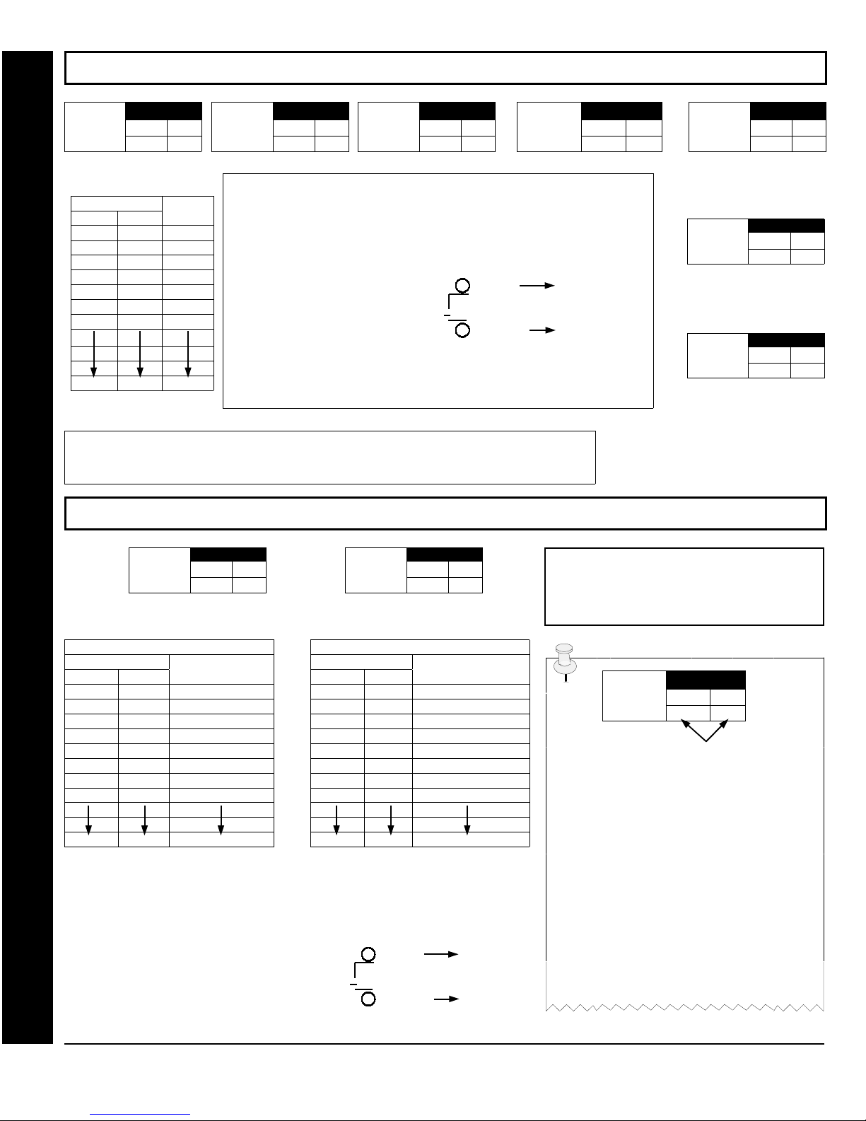
Page 24
WI1387 7/05
SYSTEM DELAYS & TIMEOUTS (ADDRESS 0000-0002, 1413, 1417, 2050 & 2055)
ADDRESS 0000
EXIT
DELAY
(sec.)
LEFT RIGHT
[Default = 3 C]
DATA ENTRIES
LEFT RIGHT
DELAY/
TIMEOUT
blank (•) blank (•) 0 sec.
blank (•) F 15 sec.
1 E 30 sec.
2 D 45 sec.
3 C 60 sec.
5 0 90 sec.
7 8 120 sec.
F F 255 min.
ENTRY
DELAY 1
(sec.)
ADDRESS 0001
LEFT RIGHT
[Default = 1 E]
1. Select delay/timeout (0-255 sec.) from the table shown.
2. Enter in corresponding address locations above (left and right digits).
3. For a desired delay/timeout not listed do the following:
A. Choose a desired delay/timeout, ex: 20 sec.
B. Divide it by 16
4. Press U or D to save.
EXIT/ENTRY DELAYS: Apply only to zones programmed with the following options “Exit/
Entry 1, Exit/Entry 2, Exit/Entry Follower”.
to above table, except in hours.
ENTRY
DELAY 2
(sec.)
ADDRESS 0002
LEFT RIGHT
[Default = 1 E]
PGM2 Output
Access C ntrl
Timeout (sec.)
[Default = blank (•) blank (•)]
1 Quotient Left Digit
16 20
16
4 Remainder Right Digit
Sensor Watch Time Options are similar
NOTE:
ADDRESS 1413
PROGRAMMING TIMEOUTS: Either use the tables provided or calculate your own timeout
using the steps indicated. WARNING:
Timers have uncertainty of +/-1sec, so a "time" of 1
second may actually timeout IMMEDIATELY.
SYSTEM DELAYS & TIMEOUTS (ADDRESS 1418 & 1419)
LEFT RIGHT
ABORT
DELAY
(sec.)
ADDRESS 1417
LEFT RIGHT
[Default = 1 E]
Time
(Hrs.)
ADDRESS 2050
LEFT RIGHT
Sensor Watch
[Default = 24 HRS = 1 8
(min.)
ADDRESS 2055
LEFT RIGHT
Report Cancel
Window
[Default = zero minutes =
blank (•) blank (•)]
CHIME
TIME
(¼sec.)
ADDRESS 1418
LEFT RIGHT
[Default = 2 sec. = blank (•) 8]
CHIME TIMEOUT OPTIONS
DATA ENTRIES
LEFT RIGHT
Direct Address Program Mode
blank (•) blank (•) (0) ¼sec. = 0 sec.
TIMEOUT
blank (•) 2 (2) ¼sec. = ½ sec.
blank (•) 3 (3) ¼sec. = ¾ sec.
blank (•) 4 (4) ¼sec. = 1 sec.
blank (•) 5 (5) ¼sec. = 1.25 sec.
blank (•) 6 (6) ¼sec. = 1.5 sec.
blank (•) 7 (7) ¼sec. = 1.75 sec.
blank (•) 8 (8) ¼sec. = 2 sec.
F F (255) ¼sec. = 63.25
1. Select delay/timeout from the table shown.
2. Enter in corresponding address locations above (left and right digits).
3. For a desired delay/timeout not listed do the following:
A. Choose a desired delay/timeout, ex: 20
B. Divide it by 16
4. Press U or D to save.
AC Fail
Report Delay
(min.)
ADDRESS 1419
LEFT RIGHT
[Default = 60 mins. = 3 C]
AC FAIL REPORT DELAY OPTIONS
DATA ENTRIES
LEFT RIGHT
TIMEOUT
blank (•) blank (•) blank (•)
blank (•) 1 1
blank (•) 2 2
blank (•) 3 3
blank (•) 4 4
blank (•) 5 5
blank (•) 6 6
blank (•) 7 7
F F 255 min. = 4 Hr., 30 min.
1 Quotient Left Digit
16 20
16
4 Remainder Right Digit
DEFAULTS: The defaults shown on this
page and on the following pages are
automatically set after exiting the Easy
Menu Driven Mode.
Program
Option
ADDRESS LOC.
LEFT RIGHT
ENTER DATA
PROGRAMMING STEPS:
1. Lookup desired Programming Option by
Address Location (highlighted in black).
2. Select the programming option data entry
from the tables shown.
3. Enter the selected data entry in the boxes
shown.
4. For more information on a programming
option refer to the Glossary at the end of
this manual.
GEM-P1664EX Programming Instructions
X
L
NAPCO Security Systems
Page 25
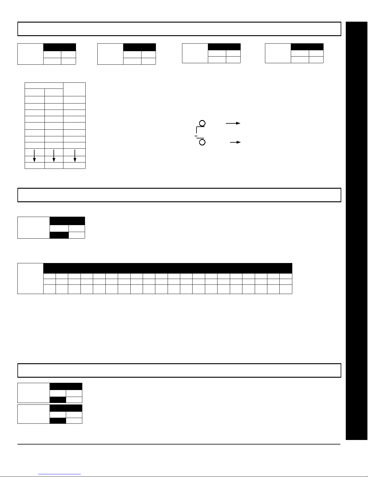
WI1387 7/05
SYSTEM OUTPUT TIMEOUTS (ADDRESS 1412 & 1414-1416)
Page 25
PGM2
Output
Timeout (min.)
[Default = blank (•) blank (•)]
ADDRESS 1412
LEFT RIGHT
DATA ENTRIES DELAY/
LEFT RIGHT
blank (•) blank (•) 0 min.
blank (•) 1 1 min.
blank (•) 2 2 min.
blank (•) 3 3 min.
blank (•) 4 4 min.
blank (•) 5 5 min.
blank (•) 6 6 min.
1 blank (•) 16 min.
F F 255 min.
TIMEOUT
DOWNLOAD/CALLBACK OPTIONS (ADDRESS 2059 & 0526-0545)
No. Rings
Before
Pickup
[Default = blank (•) blank (•)]
ADDRESS 2059
LEFT RIGHT
blank (•)
Alarm
Output
Timeout (min.)
[Default = 15 mins. = (blank) F]
1. Select delay/timeout (0-255 min.) from the table shown.
2. Enter in corresponding address locations above (left and right digits).
3. For a desired delay/timeout not listed do the following:
ADDRESS 1414
LEFT RIGHT
Pulse Alarm
Output
Timeout (min.)
[Default = 15 mins. = (blank) F]
ADDRESS 1415
LEFT RIGHT
PGM1
Output
Timeout (min.)
[Default = blank (•) blank (•)]
ADDRESS 1416
LEFT RIGHT
A. Choose a desired delay/timeout, ex: 20 min.
B. Divide it by 16
4. Press U or D to save.
1 Quotient Left Digit
16 20
16
4 Remainder Right Digit
OUTPUT TIMEOUTS: If a timeout of “0 min.” is selected, then the output will remain active (ON)
until the system is reset or disarmed.
NUMBER OF RINGS BEFORE PICKUP: Enter the number of rings before automatic pickup by the control
panel when downloading from a computer (see installation instructions WI1388 for more information).
1. Enter in right digit only (left digit is not used).
2. Valid entries are: 3-9, 0 = 10, B = 11, C = 12, D = 13, E = 14, F = 15
NOTE: Default is 15 Rings. Dark shaded data shows option not available.
Direct Address Program Mode
3. Press U or D to save.
CALLBACK
Telephone
Number
(Digits 1-20)
[Default = blank (•) for all digits 1-20]
0526 0527 0528 0529 0530 0531 0532 0533 0534 0535 0536 0537 0538 0539 0540 0541 0542 0543 0544 0545
R R R R R R R R R R R R R R R R R R R R
ADDRESS 0526-0545 (RIGHT DIGITS 1-20)
CALLBACK TELEPHONE NUMBER: Enter telephone number to be used when downloading from a computer (see installation instructions WI1388 for more information).
1. Enter in right digit only (left digit is not used).
2. Enter up to 20 digits from left to right. NOTE: Leave trailing boxes blank (•). For a zero, press G0.
3. Valid entries are: 1-9, B = *button, C = #button, D = 3 sec. pause, E = Wait for dial tone, F = ignore location.
4. Press U or D to save.
PAGER FORMAT OPTIONS (ADDRESS 0546 & 0547)
LEADING DIGITS FOR PAGER FORMAT: In Pager Format reporting, the message typically begins with “00”.
Leading Digits for
Pager Format
(1st Digit) blan k (•)
Leading Digits for
Pager Format
(2nd Digit) blank (•)
[Default = blank (•) blank (•)]
ADDRESS 0546
LEFT RIGHT
ADDRESS 0547
LEFT RIGHT
However, for some pager services, this will cause the Pager's Voice Mail feature to activate. This option allows you
to program these digits to any number desired. A typical Pager report is “003 22 1234”, where 3 is the Event, 22 is
the zone, and 1234 is the Subscriber ID number. For example, if the Leading Digits are programmed as “98”, the
Pager report will now appear as “983 22 1234”. NOTE: See CS Receiver Options to select Pager Format.
1. Enter in 1st and 2nd Leading Digits in right digit only (left digit is not used) as shown.
2. Valid entries are: 0-9.
3. Press U or D to save.
L
NAPCO Security Systems
GEM-P1664EX Programming Instructions
X
Page 26
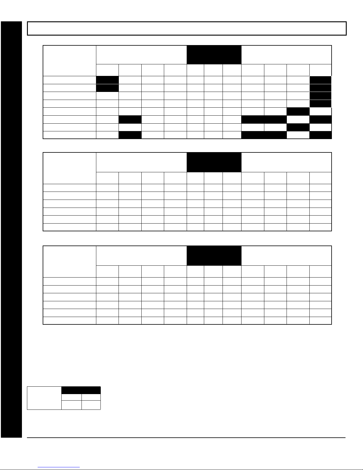
Page 26
WI1387 7/05
SYSTEM OPTIONS (ADDRESS 0836-0871 & 2045)
GLOBAL SYSTEM EVENT/TROUBLE
SYSTEM RESPONSE
ACTIVATED BY GLOBAL
EVENT/TROUBLE
Alarm Output 8 4 2 1
Pulsed Alarm Output 8 4 2 1
PGM1 Output 8 4 2 1
PGM2 Output 8 4 2 1
Report Event Telco 1 8 4 2 1
Report Restore Telco 1 8 4 2 1
Report Event Telco 3 8 4 2 1
Report Restore Telco 3 8 4 2 1
LEFT DATA VALUES (CIRCLE
Bell
Superv.
TAMPER
EZM
AC FAIL LOW
BATTERY
)
ADDRESS 0836-0843
LEFT ADDR RIGHT
0836
0837
0838
0839
0840
0841
0842
0843
8 4 2 1
8 4 2 1
8 4 2 1
8 4 2 1
8 4 2 1
8 4 2 1
8 4 2 1
8 4 2 1
GLOBAL SYSTEM EVENT/TROUBLE
RIGHT DATA VALUES (CIRCLE
MEMORY
FAILURE
RF RCVR.
TROUBLE
TELCO
FAILURE
[Default = blank (•) blank (•) from address 0836-0843] Note: If Test Timer is enabled (above), Digital Dialer Test is also enabled.
AREA 1 SYSTEM EVENT/TROUBLE
SYSTEM RESPONSE
ACTIVATED BY AREA 1
EVENT/TROUBLE
Pulsed Alarm Output 8 4 2 1
Alarm Output 8 4 2 1
PGM1 Output 8 4 2 1
PGM2 Output 8 4 2 1
Report Event Telco 1 8 4 2 1
Report Event Telco 3 8 4 2 1
LEFT DATA VALUES (CIRCLE
Keyfob
Low Batt.
FAIL TO
CLOSE
FAIL TO
OPEN
)
KEYPAD
TAMPER
[Default = blank (•) blank (•) from address 0856-0863]
ADDRESS 0856-0863
LEFT ADDR RIGHT
0856
0857
0858
0860
0861
0863
8 4 2 1
8 4 2 1
8 4 2 1
8 4 2 1
8 4 2 1
8 4 2 1
AREA 1 SYSTEM EVENT/TROUBLE
RIGHT DATA VALUES (CIRCLE
KEYPAD
AUX.
KEYPAD
FIRE
KEYPAD
PANIC
)
TEST
TIMER
)
AMBUSH
SYSTEM RESPONSE
ACTIVATED BY AREA 2
EVENT/TROUBLE
Pulsed Alarm Output 8 4 2 1
Direct Address Program Mode
Alarm Output 8 4 2 1
PGM1 Output 8 4 2 1
PGM2 Output 8 4 2 1
Report Event Telco 1 8 4 2 1
Report Event Telco 3 8 4 2 1
1. Select the desired option by circling the data values for each digit (left
and right).
2. Add the data values (ex: F=15=(1+2+4+8) from the selected options. See page 23).
3. Enter in address location (left and right digits). NOTE: Dark shaded data value box shows option not available.
4. Press U or D to save.
Global
Ambush Code
[Default = blank (•) blank (•)]
ADDRESS 2045
LEFT RIGHT
AREA 2 SYSTEM EVENT/TROUBLE
LEFT DATA VALUES (CIRCLE
Keyfob
Low Batt.
FAIL TO
CLOSE
FAIL TO
OPEN
)
KEYPAD
TAMPER
ADDRESS 0864-0871
LEFT ADDR RIGHT
0864
0865
0866
0868
0869
0871
[Default = blank (•) blank (•) from address 0864-0871]
GLOBAL AMBUSH CODE:
If “Enable Global Ambush Code” (Address 1422) is selected and Address 2045 is left blank (•), then
It is the 2-digits entered immediately prior to the regular disarm code.
AREA 2 SYSTEM EVENT/TROUBLE
RIGHT DATA VALUES (CIRCLE
KEYPAD
AUX.
KEYPAD
FIRE
8 4 2 1
8 4 2 1
8 4 2 1
8 4 2 1
8 4 2 1
8 4 2 1
KEYPAD
PANIC
AMBUSH
the 2-digit Global Ambush Code is “99”. If “Enable Global Ambush Code” is selected and Address
2045 is not left blank (•), then the 2-digit Global Ambush Code is the two digits entered in address
2045.
Enter in address location (both left and right digits) ; valid entries are 1-9.
Press U or D to save.
)
GEM-P1664EX Programming Instructions
X
L
NAPCO Security Systems
Page 27
WI1387 7/05
SYSTEM OPTIONS (ADDRESS 0872-0887)
Page 27
AREA 3 SYSTEM EVENT/TROUBLE
SYSTEM RESPONSE
ACTIVATED BY AREA 3
EVENT/TROUBLE
Pulsed Alarm Output 8 4 2 1
Alarm Output 8 4 2 1
PGM1 Output 8 4 2 1
PGM2 Output 8 4 2 1
Report Event Telco 1 8 4 2 1
Report Event Telco 3 8 4 2 1
LEFT DATA VALUES (CIRCLE
Keyfob
Low Batt.
FAIL TO
CLOSE
FAIL TO
OPEN
)
KEYPAD
TAMPER
[Default = blank (•) blank (•) from address 0872-0879]
AREA 4 SYSTEM EVENT/TROUBLE
SYSTEM RESPONSE
ACTIVATED BY AREA 4
EVENT/TROUBLE
Pulsed Alarm Output 8 4 2 1
Alarm Output 8 4 2 1
PGM1 Output 8 4 2 1
PGM2 Output 8 4 2 1
Report Event Telco 1 8 4 2 1
Report Event Telco 3 8 4 2 1
LEFT DATA VALUES (CIRCLE
Keyfob
Low Batt.
FAIL TO
CLOSE
FAIL TO
OPEN
)
KEYPAD
TAMPER
[Default = blank (•) blank (•) from address 0880-0887]
ADDRESS 0856-0863
LEFT ADDR RIGHT
0872
0873
0874
0876
0877
0879
ADDRESS 0864-0871
LEFT ADDR RIGHT
0864
0865
0866
0868
0869
0871
8 4 2 1
8 4 2 1
8 4 2 1
8 4 2 1
8 4 2 1
8 4 2 1
AREA 3 SYSTEM EVENT/TROUBLE
RIGHT DATA VALUES (CIRCLE
KEYPAD
AUX.
KEYPAD
AUX.
KEYPAD
FIRE
AREA 4 SYSTEM EVENT/TROUBLE
RIGHT DATA VALUES (CIRCLE
KEYPAD
FIRE
8 4 2 1
8 4 2 1
8 4 2 1
8 4 2 1
8 4 2 1
8 4 2 1
KEYPAD
PANIC
KEYPAD
PANIC
)
AMBUSH
)
AMBUSH
Direct Address Program Mode
1. Select the desired option by circling the data values for each digit (left and right).
2. Add the data values (ex: F=15=(1+2+4+8) from the selected options. See page 23).
3. Enter in address location (left and right digits). NOTE: Dark shaded data value box shows option not available.
4. Press U or D to save.
L
NAPCO Security Systems
GEM-P1664EX Programming Instructions
X
Page 28
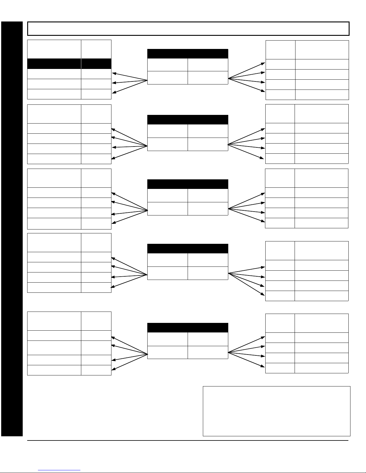
Page 28
WI1387 7/05
SYSTEM OPTIONS (ADDRESS 1420-1424)
SYSTEM OPTIONS
RESERVED
Enable AutoArm if not
closed at end of Window
Enable Keypad Time/
Date Display
Disable Zone Fault
Scrolling
SYSTEM OPTIONS
Access Control on
PGM2 Output
Maintained Keyswitch
Arming
Enable Manager's Mode
Disable Keypad Instant
Mode
SYSTEM OPTIONS
Disable Keypad Function
Mode Download
Disable Callback
Download
Chirp Output on Keyfob
Arm/Disarm
Change Pulse Output to
Temporal Output
SYSTEM OPTIONS
Line-Fault Test only
when Armed**
Enable Line-Fault Test**
Inhibit System Trouble
Audible at Keypad
Select Alarm Output for
Direct Address Program Mode
Keyfob Chirp
SYSTEM OPTIONS
Don't Clear PGM2 Output
with Disarm
Disable 2nd Call Ans.
Machine Override
Enable Loop Supervision
Disable Code Required
for EZ Bypass
§
LEFT DATA
VALUES
(CIRCLE
1
2
4
8
LEFT DATA
VALUES
(CIRCLE
1
2
4
8
LEFT DATA
VALUES
(CIRCLE
1
2
4
8
LEFT DATA
VALUES
(CIRCLE
1
2
4
8
LEFT DATA
VALUES
(CIRCLE
1
2
4
8
RIGHT DATA
)
LEFT DIGIT (SUM
OF DATA VALUES)
ADDRESS 1420
RIGHT DIGIT (SUM
OF DATA VALUES)
[Default = blank (•) blank (•)]
)
LEFT DIGIT (SUM
OF DATA VALUES)
ADDRESS 1421
RIGHT DIGIT (SUM
OF DATA VALUES)
[Default = blank (•) blank (•)]
)
LEFT DIGIT (SUM
OF DATA VALUES)
§
This feature must be programmed in Fire
Alarm applications.
)
LEFT DIGIT (SUM
OF DATA VALUES)
ADDRESS 1422
RIGHT DIGIT (SUM
OF DATA VALUES)
[Default = blank (•) blank (•)]
ADDRESS 1423
RIGHT DIGIT (SUM
OF DATA VALUES)
[Default = blank (•) blank (•)]
For Address 1423
Menu Question “
If yes, then [Default = •(blank) 1].
If no, then [Default = •(blank) •(blank)].
)
LEFT DIGIT (SUM
OF DATA VALUES)
: Default depends on Easy
EZ ZONE DOUBLING? Y/N
ADDRESS 1424
RIGHT DIGIT (SUM
OF DATA VALUES)
”.
[Default = blank (•) blank (•)]
VALUES
(CIRCLE
1
2
4
8
RIGHT DATA
VALUES
(CIRCLE
1
2
4
8
RIGHT DATA
VALUES
(CIRCLE
1
2
4
8
RIGHT DATA
VALUES
(CIRCLE
1
2
4
8
RIGHT DATA
VALUES
(CIRCLE
1
2
4
8
SYSTEM OPTIONS
)
Opening Report Only after
Alarm Report
Closing Report Only on
Conditional Close
Incl. Sel./Grp. Bypass in
Cond. Close /Status
Status Report
SYSTEM OPTIONS
)
Auto Bell Test
on Arming
Auto Reset after Burglary
Output Timeout
Suppress Bypass
Reminder when Armed
Enable Local Alarm on
First Zone AND Trip
SYSTEM OPTIONS
)
Interior Normally By-
passed
Enable Global Ambush
Code ***
Reset Day Zone with Arm/
Disarm Only
Enable Residential Fire
SYSTEM OPTIONS
)
Enable Zone Doubling
(Zones 9-16)
Wireless Trouble
Activates Telco 1
Wireless Trouble
Activates Telco 3
Enable Alarm Output on Telco
Fail only when Armed
SYSTEM OPTIONS
)
Automatic Interior Bypass/
Easy Exit
Veri-phone Zones Trip
PGM2 Output
Veri-phone Audio Priority
Over Alarms
Resound on Wireless
Smoke Low Battery
1. Select the desired option by circling the data values for
each digit (left and right).
2. Add the data values (ex: F=15=(1+2+4+8) from the selected
options. See page 23).
3. Enter in address location (left and right digits). NOTE: Dark
shaded data value box shows option not available.
4. Press U or D to save.
GEM-P1664EX Programming Instructions
X
*NOTE: Address 1423:
ZONE DOUBLING? Y/N
blank (•)].
**NOTE:
To select “Line-Fault Test only when Armed”, you must also
select “Enable Line-Fault Test” at address 1423.
***NOTE:
If “Enable Global Ambush Code” in Address 1422 is selected,
then program the 2-digit “Global Ambush Code” in Address 2045. If
Address 2045 is left blank (•), then, the 2-digit “Global Ambush Code”
will be “99”.
Default depends on Easy Menu Question :“
”. If yes, then [Default = 1]. If no, then [Default =
L
NAPCO Security Systems
EZ
Page 29
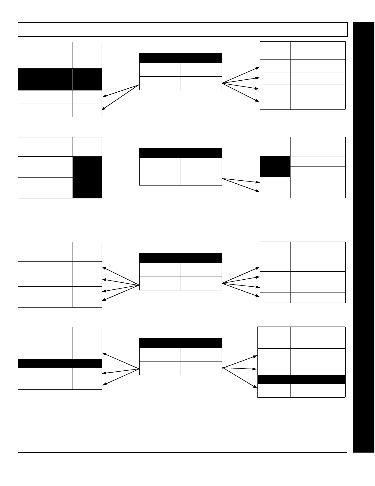
WI1387 7/05
SYSTEM OPTIONS (ADDRESS 2051-2054)
Page 29
SYSTEM OPTIONS LEFT DATA
RESERVED 1
RESERVED 2
Disable System Trouble
Audible Timeout
Enable "K Series" Style
††
NOTE:
SYSTEM OPTIONS
RESERVED 1
RESERVED
RESERVED
RESERVED 8
††
Keypads
This option is for reference only and cannot be changed.
E15 LUG/
VALUES
(CIRCLE
LEFT DATA
VALUES
(CIRCLE
RIGHT DATA
VALUES
ADDRESS 2051
)
4
8
)
2
4
LEFT DIGIT (SUM
OF DATA VALUES)
RIGHT DIGIT (SUM
OF DATA VALUES)
[Default = blank (•) blank (•)]
ADDRESS 2052
LEFT DIGIT (SUM
OF DATA VALUES)
RIGHT DIGIT (SUM
OF DATA VALUES)
[Default = blank (•) blank (•)]
(CIRCLE
1 Enable Keypad Set Time/
2 Enable Cancel Report to
4 Disable [ON/OFF] as Easy
8 Enable GEM-PRINT
RIGHT DATA
VALUES
(CIRCLE
1 RESERVED
2
4
8
SYSTEM OPTIONS
)
Date Message
Telco 3
Exit
Module
E15 LUG/
SYSTEM OPTIONS
)
RESERVED
Lug E15 Area 1 Armed
Away Only*
PGM on RF Transmitter
Tamper
Direct Address Program Mode
*Note: (Address 2052) If this feature is not selected, the E15 Lug
will, by default, activate when the system is armed (all areas).
SYSTEM OPTIONS
Digital Dialer Rpt Enter /
Exit Test Mode
Disable Call Waiting on
1st Attempt
Enable Keypad 1 Only
Programming
Enable CP-01 Egress
Tones Only
SYSTEM OPTIONS
Enable EN501 Grade 3
Operation
RESERVED 2
Enable 2-Count Swinger
Shutdown
Enable Keypad Blanking 8
1. Select the desired option by circling the data values for each digit (left and right).
2. Add the data values (ex: F=15=(1+2+4+8) from the selected options. See page 23).
3. Enter in address location (left and right digits).
4. Press U or D to save.
LEFT DATA
VALUES
(CIRCLE
1
2
4
8
LEFT DATA
VALUES
(CIRCLE
1
4
)
LEFT DIGIT (SUM
OF DATA VALUES)
ADDRESS 2053
RIGHT DIGIT (SUM
OF DATA VALUES)
[Default = blank (•) blank (•)]
)
LEFT DIGIT (SUM
OF DATA VALUES)
ADDRESS 2054
RIGHT DIGIT (SUM
OF DATA VALUES)
[Default = blank (•) blank (•)]
Dark shaded data value box shows option not available.
NOTE:
RIGHT DATA
VALUES
(CIRCLE
1
2
4
8
RIGHT DATA
VALUES
(CIRCLE
1 Enable TCP/IP Commu-
2 Enable EN501 User Code
4 RESERVED
8 Enable Display Time On
SYSTEM OPTIONS
)
Exit Time Restart
Sound Alarm On Exit Error
Rpt Exit Err/Recent Close
Enable CP-01 Limits
SYSTEM OPTIONS
)
nications
Access Level
Blanked Keypads
L
NAPCO Security Systems
GEM-P1664EX Programming Instructions
X
Page 30
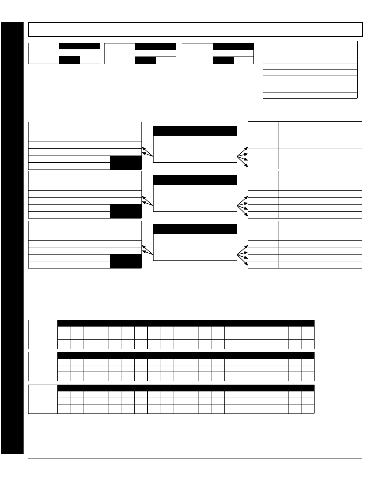
Page 30
WI1387 7/05
CS RECEIVER OPTIONS (ADDRESS 0460-0525)
CS Receiver 1
Format blank (•)
Default for CS Receiver 1 Format depends on Easy Menu Question “RCVR FORMAT”. [Default = •(blank) •
(blank)] for CS Receivers 2 and 3 Formats.
ADDRESS 0460
LEFT RIGHT
CS Receiver 2
Format blank (•)
ADDRESS 0482
LEFT RIGHT
CS Receiver 3
Format blank (•)
ADDRESS 0504
LEFT RIGHT
CS RECEIVER FORMATS: Up to 3 CS Formats may be programmed.
1. Select the desired CS Receiver Format from the table shown.
2. Enter in the corresponding right digit address location (left digit is not used) for each CS
Receiver.
3. Press U or D to save.
CS RECEIVER TELCO 1 OPTIONS
Sum Check
3/1 with Extended Restores
RESERVED
RESERVED
CS RECEIVER TELCO 2 OPTIONS
Sum Check
3/1 with Extended Restores
RESERVED
RESERVED
CS RECEIVER TELCO 3 OPTIONS
Sum Check
3/1 with Extended Restores
RESERVED
RESERVED
Dark shaded data value box shows option not available.
NOTE:
LEFT DATA
VALUES
)
(CIRCLE
LEFT DATA
VALUES
(CIRCLE
LEFT DATA
VALUES
(CIRCLE
1
2
4
8
1
2
4
8
1
2
4
8
LEFT DIGIT (SUM
OF DATA VALUES)
[Default = blank (•) blank (•)]
)
LEFT DIGIT (SUM
OF DATA VALUES)
[Default = blank (•) blank (•)]
)
LEFT DIGIT (SUM
OF DATA VALUES)
[Default = blank (•) blank (•)]
ADDRESS 0461
RIGHT DIGIT (SUM
OF DATA VALUES)
ADDRESS 0483
RIGHT DIGIT (SUM
OF DATA VALUES)
ADDRESS 0505
RIGHT DIGIT (SUM
OF DATA VALUES)
CS RECEIVER OPTIONS: Select options for any of the three CS Receivers.
1. Select the desired option by circling the data values for each digit (left and right).
2. Add the data values (ex: F=15=(1+2+4+8) from the selected options. See page 23).
Direct Address Program Mode
3. Enter in address location (left and right digits).
Dark shaded data value box shows option not available. Press U or D to save.
NOTE:
ENTRY
blank
RIGHT DATA
VALUES
(CIRCLE
1
2
4
8
RIGHT DATA
VALUES
(CIRCLE
1
2
4
8
RIGHT DATA
VALUES
(CIRCLE
1
2
4
8
DATA
2 Radionics Fast
3 Silent Knight Fast
4 Radionics, DCI, Franklin Slow
5 Universal High Speed
B SIA
C Ademco Point ID
E Pager *
CS RECEIVER 1 FORMAT
(•) Ademco Sl ow, Silent Knight Slow
*See Pager Format Options to program
Leading Digits for Pager Format.
CS RECEIVER TELCO 1 OPTIONS
)
1400Hz Handshake/Kissoff *
2300Hz Handshake/Kissoff *
Enable Zone Number on Pulse Alarm
Single Digit Only
CS RECEIVER TELCO 2 OPTIONS
)
1400Hz Handshake/Kissoff *
2300Hz Handshake/Kissoff *
Enable Zone Number on Pulse Alarm
Single Digit Only
CS RECEIVER TELCO 3 OPTIONS
)
1400Hz Handshake/Kissoff *
2300Hz Handshake/Kissoff *
Enable Zone Number on Pulse Alarm
Single Digit Only
* If both are selected,
NOTE:
1400Hz has priority over 2300Hz.
CS Receiver 1 ADDRESS 0462-0481 (RIGHT DIGITS 1-20)
Telephone
Number
(Digits 1-20)
CS Receiver 2 ADDRESS 0484-0503 (RIGHT DIGITS 1-20)
Telephone
Number
(Digits 1-20)
CS Receiver 3 ADDRESS 0506-0525 (RIGHT DIGITS 1-20)
Telephone
Number
(Digits 1-20)
0462 0463 0464 0465 0466 0467 0468 0469 0470 0471 0472 0473 0474 0475 0476 0477 0478 0479 0480 0481
R R R R R R R R R R R R R R R R R R R R
0484 0485 0486 0487 0488 0489 0490 0491 0492 0493 0494 0495 0496 0497 0498 0499 0500 0501 0502 0503
R R R R R R R R R R R R R R R R R R R R
0506 0507 0508 0509 0510 0511 0512 0513 0514 0515 0516 0517 0518 0519 0520 0521 0522 0523 0524 0525
R R R R R R R R R R R R R R R R R R R R
CS RECEIVER TELEPHONE NUMBERS: Enter telephone numbers for any of the three CS Receivers (Telco 1, 2 & 3).
1. Enter in right digit only (left digit is not used).
2. Enter up to 20 digits from left to right. NOTE: Leave trailing boxes blank (•). For a zero, press
3. Valid entries are: 1-9, B = *button, C = #button, D = 3 sec. pause, E = Wait for dial tone, F = ignore location. Press U or D to save.
GEM-P1664EX Programming Instructions
X
G0
L
Default for CS
Receiver 1
Telephone Number
depends on Easy
Menu Question
“CENTRAL PHONE
#”.
[Default = blank (•)]
across digits 1-20 for
CS Receiver
Telephone Numbers
2 and 3.
.
NAPCO Security Systems
Page 31
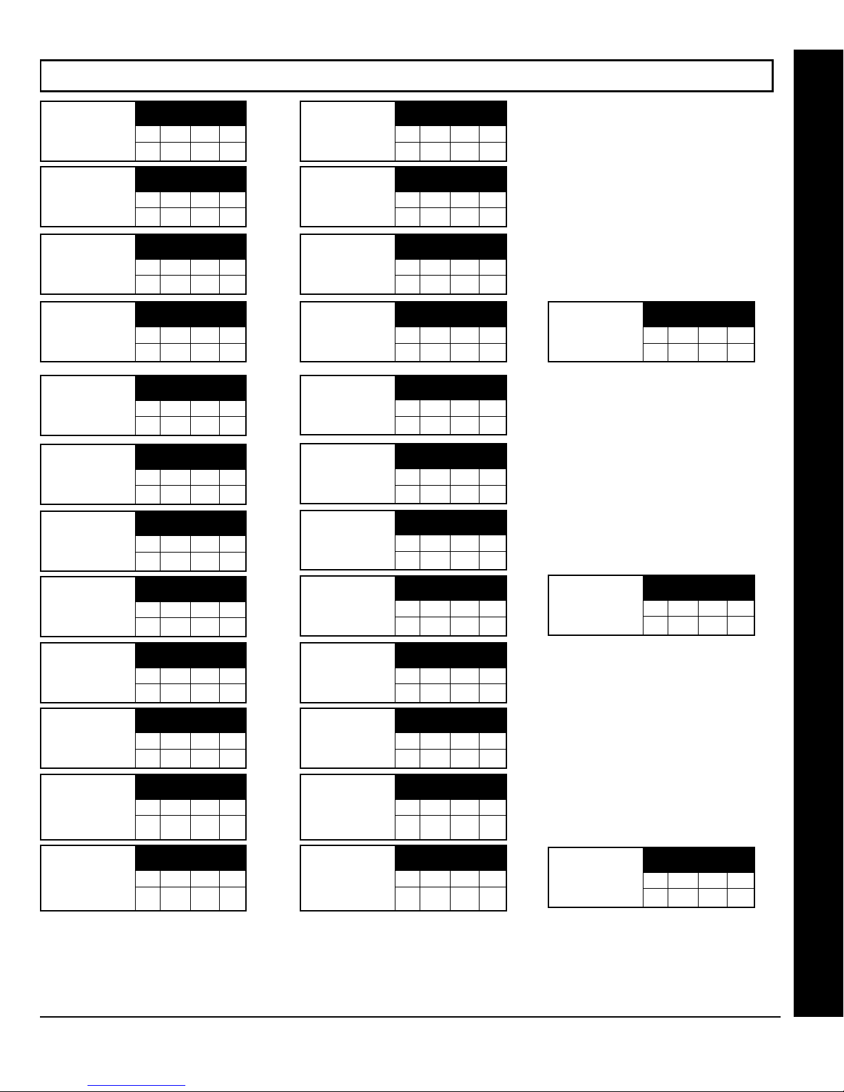
WI1387 7/05
CS SUBSCRIBER ID OPTIONS (ADDRESS 0560-0667)
Page 31
CS Telco 1 Sub-
scriber Opening/
Closing ID Number
(Area 1)
CS Telco 1 Sub-
scriber Opening/
Closing ID Number
(Area 3)
CS Telco 1 Subscriber Event ID
Number (Area 1)
CS Telco 1 Subscriber Event ID
Number (Area 3)
CS Telco 2 Sub-
scriber Opening/
Closing ID Number
(Area 1)
CS Telco 2 Sub-
scriber Opening/
Closing ID Number
(Area 3)
CS Telco 2 Subscriber Event ID
Number (Area 1)
ADDRESS 0560-0563
(RIGHT DIGITS 1-4)
0560 0561 0562 0563
ADDRESS 0568-0571
(RIGHT DIGITS 1-4)
0568 0569 0570 0571
ADDRESS 0576-0579
(RIGHT DIGITS 1-4)
0576 0577 0578 0579
ADDRESS 0584-0587
(RIGHT DIGITS 1-4)
0584 0585 0586 0587
ADDRESS 0596-0599
(RIGHT DIGITS 1-4)
0596 0597 0598 0599
ADDRESS 0604-0607
(RIGHT DIGITS 1-4)
0604 0605 0606 0607
ADDRESS 0612-0615
(RIGHT DIGITS 1-4)
0612 0613 0614 0615
Closing ID Number
Closing ID Number
Closing ID Number
Closing ID Number
CS Telco 1 Sub-
scriber Opening/
(Area 2)
CS Telco 1 Sub-
scriber Opening/
(Area 4)
CS Telco 1 Subscriber Event ID
Number (Area 2)
CS Telco 1 Subscriber Event ID
Number (Area 4)
CS Telco 2 Subscriber Opening/
(Area 2)
CS Telco 2 Subscriber Opening/
(Area 4)
CS Telco 2 Subscriber Event ID
Number (Area 2)
ADDRESS 0564-0567
(RIGHT DIGITS 1-4)
0564 0565 0566 0567
ADDRESS 0572-0575
(RIGHT DIGITS 1-4)
0572 0573 0574 0575
ADDRESS 0580-0583
(RIGHT DIGITS 1-4)
0580 0581 0582 0583
ADDRESS 0588-0591
(RIGHT DIGITS 1-4)
0588 0589 0590 0591
ADDRESS 0600-0603
(RIGHT DIGITS 1-4)
0600 0601 0602 0603
ADDRESS 0608-0611
(RIGHT DIGITS 1-4)
0608 0609 0610 0611
ADDRESS 0616-0619
(RIGHT DIGITS 1-4)
0616 0617 0618 0619
CS Telco 1 Subscriber Event ID
Number (System)
ADDRESS 0592-0595
(RIGHT DIGITS 1-4)
0592 0593 0594 0595
Direct Address Program Mode
CS Telco 2 Subscriber Event ID
Number (Area 3)
CS Telco 3 Sub-
scriber Opening/
Closing ID Number
CS Telco 3 Sub-
scriber Opening/
Closing ID Number
CS Telco 3 Subscriber Event ID
Number (Area 1)
CS Telco 3 Subscriber Event ID
Number (Area 3)
(Area 1)
(Area 3)
ADDRESS 0620-0623
(RIGHT DIGITS 1-4)
0620 0621 0622 0623
ADDRESS 0632-0635
(RIGHT DIGITS 1-4)
0632 0633 0634 0635
ADDRESS 0640-0643
(RIGHT DIGITS 1-4)
0640 0641 0642 0643
ADDRESS 0648-0651
(RIGHT DIGITS 1-4)
0648 0649 0650 0651
ADDRESS 0656-0659
(RIGHT DIGITS 1-4)
0656 0657 0658 0659
CS Telco 2 Subscriber Event ID
Number (Area 4)
CS Telco 3 Sub-
scriber Opening/
Closing ID Number
(Area 2)
CS Telco 3 Sub-
scriber Opening/
Closing ID Number
(Area 4)
CS Telco 3 Sub-
scriber Event ID
Number (Area 2)
CS Telco 3 Sub-
scriber Event ID
Number (Area 4)
ADDRESS 0624-0627
(RIGHT DIGITS 1-4)
0624 0625 0626 0627
ADDRESS 0636-0639
(RIGHT DIGITS 1-4)
0636 0637 0638 0639
ADDRESS 0644-0647
(RIGHT DIGITS 1-4)
0644 0645 0646 0647
ADDRESS 0652-0655
(RIGHT DIGITS 1-4)
0652 0653 0654 0655
ADDRESS 0660-0663
(RIGHT DIGITS 1-4)
0660 0661 0662 0663
CS Telco 2 Subscriber Event ID
Number (System)
CS Telco 3 Subscriber Event ID
Number (System)
ADDRESS 0628-0631
(RIGHT DIGITS 1-4)
0628 0629 0630 0631
ADDRESS 0664-0667
(RIGHT DIGITS 1-4)
0664 0665 0666 0667
Default for CS Telco 1 Subscriber Event ID Number (Area 1) depends on Easy Menu Question “ACCOUNT #”. [Default = blank (•) blank (•) blank (•) blank (•)] for all other ID Numbers.
CS TELCO SUBSCRIBER ID NUMBERS: Enter the Subscriber Opening/Closing and Event ID Numbers for any of the 3 CS Receivers.
1. Enter in corresponding right digit address location (left digit is not used).
2. Enter 3 or 4 digits (depending on the CS receiver format) for each subscriber number from left to right. NOTE: Leave trailing boxes blank
(•). For a zero, press G0. Valid entries are: 1-9, 0 and B-F.
A is not permitted. Press [Enter] or [ON/OFF] to save.
NOTE:
L
NAPCO Security Systems
GEM-P1664EX Programming Instructions
X
Page 32
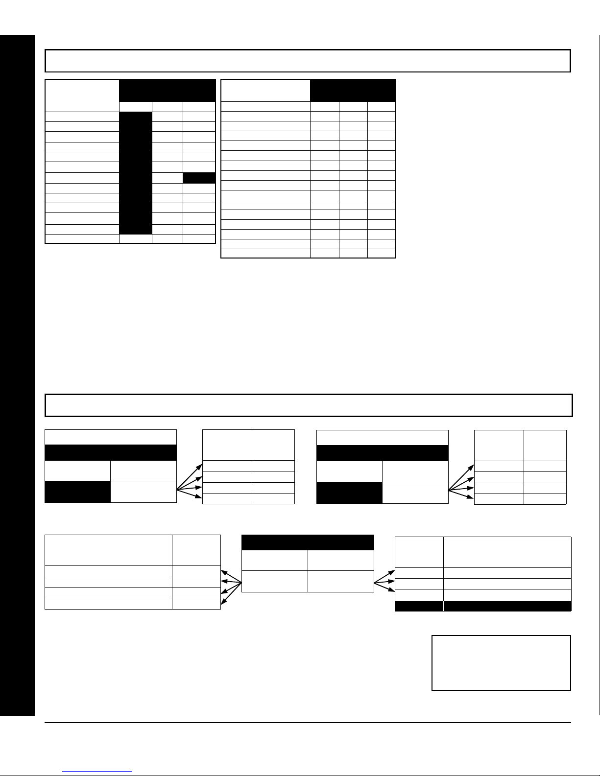
Page 32
WI1387 7/05
CS SYSTEM REPORTING OPTIONS (ADDRESS 0670-0705)
CS SYSTEM
REPORTING CODES
Xmitter Low Battery
Xmitter Supervision
Opening after Alarm
Conditional Close
[Default = blank (•) blank (•) from address 0670-0682]
[Default = blank (•) blank (•) from address 0683-0705]
Alarm Restore blank (•) 0670
Trouble
Trouble Restore
Xmitter Tamper
RESERVED
Opening
Closing
Cancel
Test Timer
ADDRESS 0670-0682
ADDR
blank (•) 0671
blank (•) 0672
blank (•) 0673
blank (•) 0674
blank (•) 0675
blank (•) 0676 blank (•)
blank (•) 0677
blank (•) 0678
blank (•) 0679
blank (•) 0680
blank (•) 0681
0682
CS SYSTEM
REPORTING CODES
Alarm Output Superv.
Keyfob Low Battery
ADDR
Telco Fail 0683
RF Rec. Troubl e
Memory Fail
Low Battery
Panel AC Fail
EZM Tamper
Ambush
Panic
Fire
Auxiliary
Tamper
Fail to Open
Fail to Close
ADDRESS 0683-0708
0684
0685
0686
0687
0688
0689 bl
0698
0699
0700
0701
0702
0703
0704
0705
CS SYSTEM REPORTING CODES:
1. Enter in corresponding address location
(left and right digits).
NOTE: Left digit is the first digit and
right digit is the second digit in a two
digit CS receiver format.
2. Valid entries are: 1-9, 0 and B-F.
NOTE:
A is not permitted.
3. To disable a code leave boxes blank
(•).
NOTE: Dark shaded data value box
shows option not available.
4. Press
or D to save.
U
CS AREA & SYSTEM REPORTING OPTIONS (ADDRESS 0785, 0786 & 0788)
DISABLE OPENING REPORTS
ADDRESS 0785
LEFT DIGIT RIGHT DIGIT (SUM
Direct Address Program Mode
blank (•)
OF DATA VALUES)
[Default = blank (•) blank (•)]
CS SYSTEM REPORT OPTIONS
(CIRCLE
Cancel Next Test Timer on any Report 1
Disable Wait for Silence (Pager Format)
Disable Wait for Handshake on Transmit
Disable Auto Dial Tone Detect 8
CS AREA & SYSTEM REPORTING OPTIONS:
1. Select the desired option by circling the data values for each digit (left and right).
2. Add the data values (ex: F=15=(1+2+4+8) from the selected options. See page 23).
3. Enter in address location (left and right digits).
NOTE: Dark shaded data value box shows option not available. Press
RIGHT DATA
(CIRCLE
LEFT DATA
VALUES
2
4
VALUES
1
2
4
8
)
AREA
)
AREA 1
AREA 2
AREA 3
AREA 4
ADDRESS 0788
LEFT DIGIT (SUM RIGHT DIGIT (SUM
[Default = blank (•) blank (•)]
DISABLE CLOSING REPORTS
ADDRESS 0786
LEFT DIGIT RIGHT DIGIT (SUM
blank (•)
OF DATA VALUES)
[Default = blank (•) blank (•)]
RIGHT DATA
VALUES
1 Backup Report on Telco 1 & 2
2 Touch-tone Dialing Only *
4 Touch-tone Dialing w/Rotary Backup *
8 RESERVED
or D to save.
U
(CIRCLE
RIGHT DATA
VALUES
(CIRCLE
1
2
4
8
CS SYSTEM REPORT OPTIONS
)
* NOTE:
If neither Touch-tone Dialing
)
AREA
AREA 1
AREA 2
AREA 3
AREA 4
nor Touch-tone w/Rotary Backup is
selected, then system defaults
automatically to Rotary Dialing. Leave
blank (•) to select Rotary Dialing.
GEM-P1664EX Programming Instructions
X
L
NAPCO Security Systems
Page 33
WI1387 7/05
Zone
ANDing
Time
Window
(seconds)
DATA ENTRIES
LEFT RIGHT
blank (•) blank (•) 0 sec.
blank (•) F 15 sec.
1 E 30 sec.
2 D 45 sec.
3 C 60 sec.
5 0 90 sec.
7 8 120 sec.
ADDRESS 2061
LEFT RIGHT
[Default = 3 C]
F F 255 min.
ZONE ANDING TIME WINDOW (ADDRESS 2061)
With Zone ANDing enabled, the system will go into alarm
:
1 Quotient Left Digit
16 20
16
4 Remainder Right Digit
DELAY/
TIMEOUT
ZONE ANDING TIME WINDOW
only if any two zones in a group are tripped within a specified period of time. With this address, this
time window is adjustable between 1 and 255 seconds. The factory default is 60 seconds. Note:
If the address is programmed to 0, the panel defaults to 60 seconds.
1. Select time window (0-255 sec.) from the table shown at left.
2. Enter in corresponding address locations above (left and right digits).
3. For a desired delay/timeout not listed do the following:
A. Choose a desired delay/timeout, ex: 20 sec.
B. Divide it by 16
4. Press U or D to save.
EXIT/ENTRY DELAYS: Apply only to zones programmed with the following options “Exit/Entry 1, Exit/Entry 2, Exit/
Entry Follower”.
tables provided or calculate your own timeout using the steps indicated. WARNING: Timers have
uncertainty of +/-1sec, so a "time" of 1 second may actually timeout IMMEDIATELY.
NOTE: Sensor Watch Time Options are similar to above table, except in hours. Either use the
Page 33
Direct Address Program Mode
KEYPAD UNBLANKING TIME WINDOW (ADDRESS 2060)
Keypad
Unblanking
Time
Window
(seconds)
[Default = 8 blank (•)]
CLOCK ADJUSTMENTS
ADDRESS 2060
LEFT RIGHT
RESERVED 1
RESERVED 2
RESERVED 4
RESERVED 8
If a keypad (RP1, RP2) is Blanked/System
KEYPAD BLANKING TIME WINDOW
event mode, enabling the keypad to normal requires a Set/Unset code + Enter (level2/3/4)
:
to come alive. The keypad will stay alive (Normal) for 128 seconds (default) or for a time in
a programmable in an EEProm location in seconds. This location, 2060, contains a 3 digit
decimal and is called Keypad Un-blanking Period. During exit/entry delay all keypads will
always come ALIVE (Normal).
See "Zone ANDing Time Window" (above) for programming procedure.
CLOCK ADJUSTMENTS (ADDRESS 2281)
LEFT DATA
VALUES
(CIRCLE
)
LEFT DIGIT (SUM
OF DATA VALUES)
*[Default = AC Source used]
**[Default = 60Hz]
ADDRESS 2281
RIGHT DIGIT (SUM
OF DATA VALUES)
RIGHT DATA
VALUES
(CIRCLE
1 Enable Daylight Saving Time
2 Clock Source (Internal Panel )*
4 Line Frequency--Enable 50Hz **
8 RESERVED
CLOCK ADJUSTMENTS
)
CLOCK ADJUSTMENTS:
1. Select the desired option by circling the data values for each digit (left and right).
2. Add the data values (ex: F=15=(1+2+4+8) from the selected options. See page 23).
3. Enter in address location (left and right digits).
NOTE: Dark shaded data value box shows option not available. Press
L
NAPCO Security Systems
or D to save.
U
GEM-P1664EX Programming Instructions
X
Page 34
Page 34
WI1387 7/05
CS ZONE REPORTING OPTIONS (ADDRESS 0720-0783)
ADDRESS 0720-0727
CONTROL PANEL ZONES REPORT CODE
ZONE 1 ZONE 2 ZONE 3 ZONE 4 ZONE 5 ZONE 6 ZONE 7 ZONE 8
0720 0721 0722 0723 0724 0725 0726
L R L R L R L R L R L R L R L R
ADDRESS 0736-0739
ZONES REPORT CODE
ZONE 17 ZONE 18 ZONE 19 ZONE 20
0736 0737 0738
L R L R L R L R
CONTROL PANEL ZONES REPORT CODE
ZONE 33 ZONE 34 ZONE 35 ZONE 36 ZONE 37 ZONE 38 ZONE 39 ZONE 40
0752 0753 0754 0755 0756 0757 0758
L R L R L R L R L R L R L R L R
ADDRESS 0768-0771
ZONES REPORT CODE
ZONE 49 ZONE 50 ZONE 51 ZONE 52
0768 0769 0770
L R L R L R L R
0739
ADDRESS 0752-0759
0771
ADDRESS 0740-0743
ZONES REPORT CODE
ZONE 21 ZONE 22 ZONE 23 ZONE 24
0740 0741 0742
L R L R L R L R
ADDRESS 0772-0775
ZONES REPORT CODE
ZONE 53 ZONE 54 ZONE 55 ZONE 56
0772 0773 0774
L R L R L R L R
0727
0743
0759
0775
ADDRESS 0728-0731
ZONES REPORT CODE
ZONE 9 ZONE 10 ZONE 11 ZONE 12
0728 0729 0730
L R L R L R L R
ADDRESS 0744-0747
ZONES REPORT CODE
ZONE 25 ZONE 26 ZONE 27 ZONE 28
0744 0745 0746
L R L R L R L R
ADDRESS 0760-0763
ZONES REPORT CODE
ZONE 41 ZONE 42 ZONE 43 ZONE 44
0760 0761 0762
L R L R L R L R
ADDRESS 0776-0779
ZONES REPORT CODE
ZONE 57 ZONE 58 ZONE 59 ZONE 60
0776 0777 0778
L R L R L R L R
0731
0747
0763
0779
ADDRESS 0732-0735
ZONES REPORT CODE
ZONE 13 ZONE 14 ZONE 15 ZONE 16
0732 0733 0734
L R L R L R L R
ADDRESS 0748-0751
ZONES REPORT CODE
ZONE 29 ZONE 30 ZONE 31 ZONE 32
0748 0749 0750
L R L R L R L R
ADDRESS 0764-0767
ZONES REPORT CODE
ZONE 45 ZONE 46 ZONE 47 ZONE 48
0764 0765 0766
L R L R L R L R
ADDRESS 0780-0783
ZONES REPORT CODE
ZONE 61 ZONE 62 ZONE 63 ZONE 64
0780 0781 0782
L R L R L R L R
0735
0751
0767
0783
ZONE REPORT
CODE OPTIONS
DATA ENTRIES
LEFT RIGHT
Direct Address Program Mode
DATA
ENTRIES MODEM CODE
LEFT
1 Fire
2 Panic
3 Burglary
4 Hold up
7 Gas Alarm
8 Heat Alarm
0 Auxiliary Alarm
B 24 Hour Auxiliary
Default for Group Zone Report Codes depends on Easy Menu Question “RCVR. FORMAT”.
NOTE: If “Zone Doubling” (Address 1423) is not enabled, then Zones 1-8 are included in the control panel and
Zones 9-64 are EZM Zones. If “Zone Doubling” is enabled, then Zones 1-16 are included in the control panel and
Zones 17-64 are EZM Zones. See Address 1455-1468 to enable “EZM Group Options”.
PULSE EVENT CODE
will be the first digit of the 2 digit reporting code. The second digit will be the
second digit of the reporting zone. For example, for zone 9 (address 0728), if the right digit is “3", then
the reporting code is ”39". For example, for zone 15 (address 0734), if the right digit is “4", then the reporting code is ”45".
MODEM CODES determine the zone types reported for the following formats: SIA and ADEMCO Point ID.
1. Select the desired Modem Code for each zone from the table shown.
2. Press U or D to save.
GEM-P1664EX Programming Instructions
X
L
NAPCO Security Systems
Page 35
WI1387 7/05
CS USER REPORTING OPTIONS (ADDRESS 0800-0817)
Page 35
LEFT DATA VALUE ADDRESS 0800
User Opening
Telco 1
User Opening
Telco 1
User Opening
Telco 1
User Opening
Telco 1
User Opening
Telco 1
User 8 User 7 User 6 User 5 LEFT RIGHT User 4 User 3 User 2 User
LEFT DATA VALUE ADDRESS 0802
LEFT DATA VALUES ADDRESS 0804
LEFT DATA VALUE ADDRESS 0806
ADDRESS 0808
8 4 2 1 8 4 2 1
User
User
User
User
24
23
22
8 4 2 1
User
User
39
User
55
User
38
User
54
40
8 4 2 1
User
56
8 4 2 1 8 4 2 1
LEFT RIGHT User
blank (•)
LEFT RIGHT User
21
User
LEFT RIGHT User
37
User
LEFT RIGHT User
53
RIGHT DATA VALUES
User
68
8 4 2 1
RIGHT DATA VALUES LEFT DATA VALUE ADDRESS 0801
RIGHT DATA VALUES LEFT DATA VALUES ADDRESS 0803
User
19
User
35
User
51
User
18
User
34
User
50
20
8 4 2 1
RIGHT DATA VALUES
36
8 4 2 1
RIGHT DATA VALUES LEFT DATA VALUES ADDRESS 0807
52
User 65 = Auto Arming/Disarming
67
User
66
User 66 = Quickloader Remote Arming/Disarming
User
65
User 67 = Easy Arming
User 68 = Keyswitch Arming
RIGHT DATA VALUES
User
User
User
User
1
16
15
14
8 4 2 1 8 4 2 1
User
User
User
17
32
8 4 2 1 8 4 2 1
LEFT DATA VALUE ADDRESS 0805
User
User
48
33
8 4 2 1 8 4 2 1
User
User
49
64
8 4 2 1
31
User
47
User
63
User
30
User
46
User
62
(Opening not applicable)
LEFT RIGHT User
13
User
LEFT RIGHT User
29
User
LEFT RIGHT User
45
User
LEFT RIGHT User
61
8 4 2 1
12
RIGHT DATA VALUES
28
RIGHT DATA VALUES
44
RIGHT DATA VALUES
60
These opening events will report
NOTE:
as the user number shown. Also, Keyfobs 1-8 (see Easy Menu Program Driven
Mode) will report as Users 57-64, respectively.
User
11
User
27
User
43
User
59
User
10
User
26
User
42
User
58
User
9
User
25
User
41
User
57
Direct Address Program Mode
LEFT DATA VALUE ADDRESS 0809
User Opening
Telco 1
LEFT DATA VALUE ADDRESS 0811
User Opening
Telco 1
LEFT DATA VALUES ADDRESS 0813
User Opening
Telco 1
LEFT DATA VALUE ADDRESS 0815
User Opening
Telco 1
User Opening
Telco 1
CS USER REPORTING OPTIONS:
1. Select the desired option by circling the data values for each digit (left and right).
2. Add the data values (ex: F=15=(1+2+4+8) from the selected options. See page 23).
3. Enter in address location (left and right digits). NOTE: Dark shaded data value box shows option not available.
4. Press U or D to save.
User 8 User 7 User 6 User 5 LEFT RIGHT User 4 User 3 User 2 User
8 4 2 1 8 4 2 1
User
User
User
User
24
23
22
8 4 2 1
User
User
39
User
55
User
38
User
54
40
8 4 2 1
User
56
8 4 2 1 8 4 2 1
ADDRESS 0817
LEFT RIGHT User
blank (•)
LEFT RIGHT User
21
8 4 2 1
User
LEFT RIGHT User
37
8 4 2 1
User
LEFT RIGHT User
53
RIGHT DATA VALUES
User
68
8 4 2 1
User
67
66
[Default = blank (•) blank (•) from address 0800-0817]
RIGHT DATA VALUES LEFT DATA VALUE ADDRESS 0810
User
User
User
User
1
16
15
14
8 4 2 1 8 4 2 1
RIGHT DATA VALUES LEFT DATA VALUES ADDRESS 0812
User
User
User
User
User
20
19
18
17
32
8 4 2 1 8 4 2 1
RIGHT DATA VALUES
User
35
User
51
User
34
User
50
36
RIGHT DATA VALUES LEFT DATA VALUES ADDRESS 0816
52
LEFT DATA VALUE ADDRESS 0814
User
User
48
33
8 4 2 1 8 4 2 1
User
User
49
64
8 4 2 1
31
User
47
User
63
User
30
User
46
User
62
LEFT RIGHT User
13
User
LEFT RIGHT User
29
User
LEFT RIGHT User
45
User
LEFT RIGHT User
61
User 65 = Auto Arming/Disarming
User 66 = Quickloader Remote Arming/Disarming
User
65
User 67 = Easy Arming
(Opening not applicable)
User 68 = Keyswitch Arming
RIGHT DATA VALUES
12
RIGHT DATA VALUES
28
RIGHT DATA VALUES
44
RIGHT DATA VALUES
60
8 4 2 1
These opening events will report
NOTE:
as the user number shown. Also, Keyfobs 1-8 (see Easy Menu Program Driven
Mode) will report as Users 57-64, respectively.
User
11
User
27
User
43
User
59
User
10
User
26
User
42
User
58
User
9
User
25
User
41
User
57
L
NAPCO Security Systems
GEM-P1664EX Programming Instructions
X
Page 36
Page 36
WI1387 7/05
CS USER REPORTING OPTIONS (ADDRESS 0818-0835)
LEFT DATA VALUE ADDRESS 0818
User Opening
Telco 3
LEFT DATA VALUE ADDRESS 0820
User Opening
Telco 3
LEFT DATA VALUES ADDRESS 0822
User Opening
Telco 3
LEFT DATA VALUE ADDRESS 0824
User Opening
Telco 3
User Opening
Telco 3
User 8 User 7 User 6 User 5 LEFT RIGHT User 4 User 3 User 2 User
8 4 2 1 8 4 2 1
User
User
User
24
23
8 4 2 1
User
User
40
39
8 4 2 1
User
User
56
55
8 4 2 1 8 4 2 1
ADDRESS 0826
LEFT RIGHT User
blank (•)
User
22
21
User
User
38
37
User
User
54
53
RIGHT DATA VALUES
User
68
8 4 2 1
RIGHT DATA VALUES LEFT DATA VALUE ADDRESS 0819
RIGHT DATA VALUES LEFT DATA VALUES ADDRESS 0821
LEFT RIGHT User
8 4 2 1
LEFT RIGHT User
8 4 2 1
LEFT RIGHT User
User
19
User
35
User
51
User
18
User
34
User
50
20
RIGHT DATA VALUES
36
RIGHT DATA VALUES LEFT DATA VALUES ADDRESS 0825
52
User 65 = Auto Arming/Disarming
67
User
66
User 66 = Quickloader Remote Arming/Disarming
User
65
User 67 = Easy Arming
User 68 = Keyswitch Arming
RIGHT DATA VALUES
User
User
User
User
1
16
15
14
8 4 2 1 8 4 2 1
User
User
User
17
32
8 4 2 1 8 4 2 1
LEFT DATA VALUE ADDRESS 0823
User
User
48
33
8 4 2 1 8 4 2 1
User
User
49
64
8 4 2 1
31
User
47
User
63
User
30
User
46
User
62
(Opening not applicable)
LEFT RIGHT User
13
User
LEFT RIGHT User
29
User
LEFT RIGHT User
45
User
LEFT RIGHT User
61
8 4 2 1
12
RIGHT DATA VALUES
28
RIGHT DATA VALUES
44
RIGHT DATA VALUES
60
These opening events will report
NOTE:
as the user number shown. Also, Keyfobs 1-8 (see Easy Menu Program Driven
Mode) will report as Users 57-64, respectively.
User
11
User
27
User
43
User
59
User
10
User
26
User
42
User
58
User
9
User
25
User
41
User
57
LEFT DATA VALUE ADDRESS 0827
User Opening
Telco 3
LEFT DATA VALUE ADDRESS 0829
User Opening
Telco 3
User 8 User 7 User 6 User 5 LEFT RIGHT User 4 User 3 User 2 User
8 4 2 1 8 4 2 1
User
User
User
User
24
23
22
8 4 2 1
LEFT RIGHT User
21
8 4 2 1
Direct Address Program Mode
LEFT DATA VALUES ADDRESS 0831
User Opening
Telco 3
LEFT DATA VALUE ADDRESS 0833
User Opening
Telco 3
User Opening
Telco 3
CS USER REPORTING OPTIONS:
1. Select the desired option by circling the data values for each digit (left and right).
2. Add the data values (ex: F=15=(1+2+4+8) from the selected options. See page 23).
3. Enter in address location (left and right digits).
4. Press U or D to save.
User
User
39
User
55
User
38
User
54
40
8 4 2 1
User
56
8 4 2 1 8 4 2 1
ADDRESS 0835
LEFT RIGHT User
blank (•)
User
LEFT RIGHT User
37
8 4 2 1
User
LEFT RIGHT User
53
RIGHT DATA VALUES
User
68
8 4 2 1
User
67
66
[Default = blank (•) blank (•) from address 0818-0835]
RIGHT DATA VALUES LEFT DATA VALUE ADDRESS 0828
User
1
RIGHT DATA VALUES LEFT DATA VALUES ADDRESS 0830
User
User
20
19
RIGHT DATA VALUES
User
36
35
RIGHT DATA VALUES LEFT DATA VALUES ADDRESS 0834
User
52
51
18
User
34
User
50
User
17
User
33
User
49
User
16
8 4 2 1 8 4 2 1
User
User
32
8 4 2 1 8 4 2 1
LEFT DATA VALUE ADDRESS 0832
User
48
8 4 2 1 8 4 2 1
User
User
64
8 4 2 1
User 65 = Auto Arming/Disarming
User 66 = Quickloader Remote Arming/Disarming
User
65
User 67 = Easy Arming
(Opening not applicable)
User 68 = Keyswitch Arming
Dark shaded data value box shows option not available.
NOTE:
15
31
User
47
63
User
14
User
30
User
46
User
62
User
LEFT RIGHT User
13
User
LEFT RIGHT User
29
User
LEFT RIGHT User
45
User
LEFT RIGHT User
61
8 4 2 1
RIGHT DATA VALUES
User
User
12
11
RIGHT DATA VALUES
User
28
27
RIGHT DATA VALUES
User
44
43
RIGHT DATA VALUES
User
60
59
These opening events will report
NOTE:
as the user number shown. Also, Keyfobs 1-8 (see Easy Menu Program Driven
Mode) will report as Users 57-64, respectively.
10
User
26
User
42
User
58
User
9
User
25
User
41
User
57
GEM-P1664EX Programming Instructions
X
L
NAPCO Security Systems
Page 37
WI1387 7/05
EZM GROUP OPTIONS (ADDRESS 1455-1468)
Page 37
EZM Group 1
ADDRESS 1455
LEFT RIGHT
blank
EZM Group 7
ADDRESS 1461
LEFT RIGHT
blank
EZM Group 13
ADDRESS 1467
LEFT RIGHT
blank
EZM Group 2
ADDRESS 1456
LEFT RIGHT
blank
EZM Group 8
ADDRESS 1462
LEFT RIGHT
blank
EZM Group 14
ADDRESS 1468
LEFT RIGHT
blank
EZM Group 3
ADDRESS 1457
LEFT RIGHT
blank
EZM Group 9
ADDRESS 1463
LEFT RIGHT
blank
EZM Group 4
ADDRESS 1458
LEFT RIGHT
blank
EZM Group 10
ADDRESS 1464
LEFT RIGHT
blank
EZM Group 5
ADDRESS 1459
LEFT RIGHT
blank
EZM Group 11
ADDRESS 1465
LEFT RIGHT
blank
EZM Group 6
ADDRESS 1460
LEFT RIGHT
blank
EZM Group 12
ADDRESS 1466
LEFT RIGHT
blank
Default depends on Easy Menu Question “# OF ZNS IN AREA 1 ENTER # ZONES” and “EZ ZONE DOUBLING? Y/N”. For example, if
64 Zones are used and Zone Doubling is not enabled, then all 14 Groups will be automatically enabled. If 64 Zones are
used and Zone Doubling is enabled, then only Groups 1-12 will be automatically enabled.
NOTE: If “Zone Doubling” (Address 1423, option 1) is not enabled, then Zones 1-8 are included in the control panel
and Zones 9-64 (Groups 1-14) are EZM Zones. If “Zone Doubling” is enabled, then Zones 1-16 are included in the
control panel and Zones 17-64 (Groups 1-12) are EZM Zones (and Groups 13 and 14 must not be used).
Direct Address Program Mode
EZM TYPE
DATA
ENTRIES OPTION
1
Not used
(No EZM
present)
4-Zone EZM
blank (•)
EZM
GROUP NORMAL DOUBLED
1 9-12 17-20
2 13-16 21-24
3 17-20 25-28
4 21-24 29-32
5 25-28 33-36
6 29-32 37-40
7 33-36 41-44
8 37-40 45-48
9 41-44 49-52
10 45-48 53-56
11 49-52 57-60
12 53-56 61-64
13 57-60
14 61-64
ZONES COVERED
EZM GROUP OPTIONS:
Up to 14 Groups of 4 Zones each may be programmed depending on the number of Zones used and which EZM modules are connected. Each Group represents 4 Zones.
1. Select EZM type from the table shown.
2. Enter either blank (•) or "1" in corresponding address locations
above.
NOTE: Dark shaded data value box shows option not available.
3. Press U or D to save.
L
NAPCO Security Systems
GEM-P1664EX Programming Instructions
X
Page 38
Page 38
AREA BELL CONTROL OPTIONS (ADDRESS 1473-1476)
Burglary Output Turns Off upon Disarm
WI1387 7/05
RESERVED
RESERVED
RESERVED
RESERVED
RESERVED
RESERVED
RESERVED
RESERVED
RESERVED
RESERVED
RESERVED
RESERVED
RESERVED
RESERVED
RESERVED
RESERVED
RESERVED
RESERVED
RESERVED
RESERVED
LEFT DATA
VALUES
(CIRCLE
1
2
4
8
LEFT DATA
VALUES
(CIRCLE
1
2
4
8
LEFT DATA
VALUES
(CIRCLE
1
2
4
8
LEFT DATA
VALUES
(CIRCLE
1
2
4
8
Burglary Output Turns Off upon Disarm
)
OF DATA VALUES)
LEFT DIGIT (SUM
ADDRESS 1473
•
[Default = blank (•) one (1)]
Burglary Output Turns Off upon Disarm
)
OF DATA VALUES)
LEFT DIGIT (SUM
ADDRESS 1474
•
[Default = blank (•) one (1)]
Burglary Output Turns Off upon Disarm
)
OF DATA VALUES)
LEFT DIGIT (SUM
ADDRESS 1475
•
[Default = blank (•) one (1)]
Burglary Output Turns Off upon Disarm
)
OF DATA VALUES)
LEFT DIGIT (SUM
ADDRESS 1476
•
[Default = blank (•) one (1)]
RIGHT DIGIT (SUM
OF DATA VALUES)
(1)
RIGHT DIGIT (SUM
OF DATA VALUES)
(1)
RIGHT DIGIT (SUM
OF DATA VALUES)
(1)
RIGHT DIGIT (SUM
OF DATA VALUES)
(1)
RIGHT DATA
VALUES
(CIRCLE
(CIRCLE
(CIRCLE
(CIRCLE
1
2
4
8
RIGHT DATA
VALUES
1
2
4
8
RIGHT DATA
VALUES
1
2
4
8
RIGHT DATA
VALUES
1
2
4
8
Disarming Area 1
)
Area 1 Burg Output Silenced
Area 2 Burg Output Silenced
Area 3 Burg Output Silenced
Area 4 Burg Output Silenced
Disarming Area 2
)
Area 1 Burg Output Silenced
Area 2 Burg Output Silenced
Area 3 Burg Output Silenced
Area 4 Burg Output Silenced
Disarming Area 3
)
Area 1 Burg Output Silenced
Area 2 Burg Output Silenced
Area 3 Burg Output Silenced
Area 4 Burg Output Silenced
Disarming Area 4
)
Area 1 Burg Output Silenced
Area 2 Burg Output Silenced
Area 3 Burg Output Silenced
Area 4 Burg Output Silenced
OUTPUT TURNS OFF UPON DISARM: Select options for any of the 4 Outputs.
Direct Address Program Mode
1. Select the desired option by circling the data values for right digit only (left is not used).
2. Add the data values (ex: F=15=(1+2+4+8) from the selected options. See page 23).
3. Enter in right digit address location. NOTE: Dark shaded data value box shows option not available.
4. Press U or D to save.
OUTPUT TURNS OFF UPON DISARM:
Select options for any of the 4 Outputs. By default, the ability to turn off an output upon disarm is not allowed. For example, the
ability to silence an Area 1 through Area 4 output via an Area 1 keypad is not enabled by default. To enable selected area output
control, enter the number (1,2,3,4) accordingly. For example, if you wish to grant an Area 1 keypad the ability to turn off an Area 2
PGM2 output, enter "2" in Address 1485.
Enter digit in address location. NOTE: Dark shaded data value box shows option not available. Press U or D to save.
GEM-P1664EX Programming Instructions
X
L
NAPCO Security Systems
Page 39
WI1387 7/05
AREA BELL CONTROL OPTIONS (ADDRESS 1477-1480)
Pulsed Burg Output Turns Off upon Disarm
Page 39
RESERVED
RESERVED
RESERVED
RESERVED
RESERVED
RESERVED
RESERVED
RESERVED
RESERVED
RESERVED
RESERVED
RESERVED
RESERVED
RESERVED
RESERVED
RESERVED
RESERVED
RESERVED
RESERVED
RESERVED
LEFT DATA
VALUES
(CIRCLE
1
2
4
8
LEFT DATA
VALUES
(CIRCLE
1
2
4
8
LEFT DATA
VALUES
(CIRCLE
1
2
4
8
LEFT DATA
VALUES
(CIRCLE
1
2
4
8
)
)
)
)
LEFT DIGIT (SUM
OF DATA VALUES)
LEFT DIGIT (SUM
OF DATA VALUES)
LEFT DIGIT (SUM
OF DATA VALUES)
LEFT DIGIT (SUM
OF DATA VALUES)
Pulsed Burg Output
Turns Off upon Disarm
ADDRESS 1477
RIGHT DIGIT (SUM
OF DATA VALUES)
•
[Default = blank (•) one (1)]
Pulsed Burg Output
Turns Off upon Disarm
ADDRESS 1478
•
[Default = blank (•) one (1)]
Pulsed Burg Output
Turns Off upon Disarm
ADDRESS 1479
•
[Default = blank (•) one (1)]
Pulsed Burg Output
Turns Off upon Disarm
ADDRESS 1480
•
[Default = blank (•) one (1)]
(1)
RIGHT DIGIT (SUM
OF DATA VALUES)
(1)
RIGHT DIGIT (SUM
OF DATA VALUES)
(1)
RIGHT DIGIT (SUM
OF DATA VALUES)
(1)
OUTPUT TURNS OFF UPON DISARM: Select options for any of the 4 Outputs.
1. Select the desired option by circling the data values for right digit only (left is not used).
RIGHT DATA
VALUES
(CIRCLE
(CIRCLE
(CIRCLE
(CIRCLE
1
2
4
8
RIGHT DATA
VALUES
1
2
4
8
RIGHT DATA
VALUES
1
2
4
8
RIGHT DATA
VALUES
1
2
4
8
Disarming Area 1
)
Area 1 Pulsed Burg Output
Area 2 Pulsed Burg Output
Area 3 Pulsed Burg Output
Area 4 Pulsed Burg Output
)
Area 1 Pulsed Burg Output
Area 2 Pulsed Burg Output
Area 3 Pulsed Burg Output
Area 4 Pulsed Burg Output
)
Area 1 Pulsed Burg Output
Area 2 Pulsed Burg Output
Area 3 Pulsed Burg Output
Area 4 Pulsed Burg Output
)
Area 1 Pulsed Burg Output
Area 2 Pulsed Burg Output
Area 3 Pulsed Burg Output
Area 4 Pulsed Burg Output
Silenced
Silenced
Silenced
Silenced
Disarming Area 2
Silenced
Silenced
Silenced
Silenced
Disarming Area 3
Silenced
Silenced
Silenced
Silenced
Disarming Area 4
Silenced
Silenced
Silenced
Silenced
Direct Address Program Mode
2. Add the data values (ex: F=15=(1+2+4+8) from the selected options. See page 23).
3. Enter in right digit address location. NOTE: Dark shaded data value box shows option not available.
4. Press U or D to save.
OUTPUT TURNS OFF UPON DISARM:
Select options for any of the 4 Outputs. By default, the ability to turn off an output upon disarm is not allowed. For example, the ability to silence an Area 1 through Area 4 output via an Area 1 keypad is not enabled by default. To enable selected area output control, enter the number (1,2,3,4) accordingly. For example, if you wish to grant an Area 1 keypad the ability to turn off an Area 2
PGM2 output, enter "2" in Address 1485.
Enter digit in address location.
L
NAPCO Security Systems
Dark shaded data value box shows option not available. Press U or D to save.
NOTE:
GEM-P1664EX Programming Instructions
X
Page 40
Page 40
AREA BELL CONTROL OPTIONS (ADDRESS 1481-1484)
PGM1 Output Turns Off upon Disarm
WI1387 7/05
RESERVED
RESERVED
RESERVED
RESERVED
RESERVED
RESERVED
RESERVED
RESERVED
RESERVED
RESERVED
RESERVED
RESERVED
RESERVED
RESERVED
RESERVED
RESERVED
RESERVED
RESERVED
RESERVED
RESERVED
LEFT DATA
VALUES
(CIRCLE
1
2
4
8
LEFT DATA
VALUES
(CIRCLE
1
2
4
8
LEFT DATA
VALUES
(CIRCLE
1
2
4
8
LEFT DATA
VALUES
(CIRCLE
1
2
4
8
)
)
)
)
PGM1 Output Turns Off upon Disarm
ADDRESS 1481
LEFT DIGIT (SUM
OF DATA VALUES)
•
[Default = blank (•) one (1)]
PGM1 Output Turns Off upon Disarm
LEFT DIGIT (SUM
OF DATA VALUES)
•
[Default = blank (•) one (1)]
PGM1 Output Turns Off upon Disarm
LEFT DIGIT (SUM
OF DATA VALUES)
•
[Default = blank (•) one (1)]
PGM1 Output Turns Off upon Disarm
LEFT DIGIT (SUM
OF DATA VALUES)
•
[Default = blank (•) one (1)]
RIGHT DIGIT (SUM
OF DATA VALUES)
ADDRESS 1482
RIGHT DIGIT (SUM
OF DATA VALUES)
ADDRESS 1483
RIGHT DIGIT (SUM
OF DATA VALUES)
ADDRESS 1484
RIGHT DIGIT (SUM
OF DATA VALUES)
(1)
(1)
(1)
(1)
RIGHT DATA
VALUES
(CIRCLE
1
2
4
8
RIGHT DATA
VALUES
(CIRCLE
1
2
4
8
RIGHT DATA
VALUES
(CIRCLE
1
2
4
8
RIGHT DATA
VALUES
(CIRCLE
1
2
4
8
Disarming Area 1
)
Area 1 PGM1 Output Silenced
Area 2 PGM1 Output Silenced
Area 3 PGM1 Output Silenced
Area 4 PGM1 Output Silenced
Disarming Area 2
)
Area 1 PGM1 Output Silenced
Area 2 PGM1 Output Silenced
Area 3 PGM1 Output Silenced
Area 4 PGM1 Output Silenced
Disarming Area 3
)
Area 1 PGM1 Output Silenced
Area 2 PGM1 Output Silenced
Area 3 PGM1 Output Silenced
Area 4 PGM1 Output Silenced
Disarming Area 4
)
Area 1 PGM1 Output Silenced
Area 2 PGM1 Output Silenced
Area 3 PGM1 Output Silenced
Area 4 PGM1 Output Silenced
OUTPUT TURNS OFF UPON DISARM: Select options for any of the 4 Outputs.
Direct Address Program Mode
1. Select the desired option by circling the data values for right digit only (left is not used).
2. Add the data values (ex: F=15=(1+2+4+8) from the selected options. See page 23).
3. Enter in right digit address location. NOTE: Dark shaded data value box shows option not available.
4. Press U or D to save.
OUTPUT TURNS OFF UPON DISARM:
Select options for any of the 4 Outputs. By default, the ability to turn off an output upon disarm is not allowed. For example, the ability to silence an Area 1 through Area 4 output via an Area 1 keypad is not enabled by default. To enable selected area output control, enter the number (1,2,3,4) accordingly. For example, if you wish to grant an Area 1 keypad the ability to turn off an Area 2
PGM2 output, enter "2" in Address 1485.
Enter digit in address location.
GEM-P1664EX Programming Instructions
X
Dark shaded data value box shows option not available. Press U or D to save.
NOTE:
L
NAPCO Security Systems
Page 41
WI1387 7/05
AREA BELL CONTROL OPTIONS (ADDRESS 1485-1488)
PGM2 Output Turns Off upon Disarm
Page 41
RESERVED
RESERVED
RESERVED
RESERVED
RESERVED
RESERVED
RESERVED
RESERVED
RESERVED
RESERVED
RESERVED
RESERVED
RESERVED
RESERVED
RESERVED
LEFT DATA
VALUES
(CIRCLE
1
2
4
8
LEFT DATA
VALUES
(CIRCLE
1
2
4
8
LEFT DATA
VALUES
(CIRCLE
1
2
4
8
)
)
)
PGM2 Output
Turns Off upon Disarm
ADDRESS 1485
LEFT DIGIT (SUM
OF DATA VALUES)
RIGHT DIGIT (SUM
OF DATA VALUES)
•
[Default = blank (•) one (1)]
PGM2 Output
Turns Off upon Disarm
ADDRESS 1486
LEFT DIGIT (SUM
OF DATA VALUES)
RIGHT DIGIT (SUM
OF DATA VALUES)
•
[Default = blank (•) one (1)]
PGM2 Output
Turns Off upon Disarm
ADDRESS 1487
LEFT DIGIT (SUM
OF DATA VALUES)
RIGHT DIGIT (SUM
OF DATA VALUES)
•
[Default = blank (•) one (1)]
(1)
(1)
(1)
RIGHT DATA
VALUES
(CIRCLE
(CIRCLE
(CIRCLE
1
2
4
8
RIGHT DATA
VALUES
1
2
4
8
RIGHT DATA
VALUES
1
2
4
8
Disarming Area 1
)
Area 1 PGM2 Burg Output
Silenced
Area 2 PGM2 Burg Output
Silenced
Area 3 PGM2 Burg Output
Silenced
Area 4 PGM2 Burg Output
Silenced
Disarming Area 2
)
Area 1 PGM2 Burg Output
Silenced
Area 2 PGM2 Burg Output
Silenced
Area 3 PGM2 Burg Output
Silenced
Area 4 PGM2 Burg Output
Silenced
Disarming Area 3
)
Area 1 PGM2 Burg Output
Silenced
Area 2 PGM2 Burg Output
Silenced
Area 3 PGM2 Burg Output
Silenced
Area 4 PGM2 Burg Output
Silenced
Direct Address Program Mode
RESERVED
RESERVED
RESERVED
RESERVED
RESERVED
LEFT DATA
VALUES
(CIRCLE
1
2
4
8
)
PGM2 Output
Turns Off upon Disarm
ADDRESS 1488
LEFT DIGIT (SUM
OF DATA VALUES)
RIGHT DIGIT (SUM
OF DATA VALUES)
•
[Default = blank (•) one (1)]
(1)
RIGHT DATA
VALUES
(CIRCLE
1
2
4
8
Disarming Area 4
)
Area 1 PGM2 Burg Output
Silenced
Area 2 PGM2 Burg Output
Silenced
Area 3 PGM2 Burg Output
Silenced
Area 4 PGM2 Burg Output
Silenced
OUTPUT TURNS OFF UPON DISARM: Select options for any of the 4 Outputs.
1. Select the desired option by circling the data values for right digit only (left is not used).
2. Add the data values (ex: F=15=(1+2+4+8) from the selected options. See page 23).
3. Enter in right digit address location. NOTE: Dark shaded data value box shows option not available.
4. Press U or D to save.
OUTPUT TURNS OFF UPON DISARM:
Select options for any of the 4 Outputs. By default, the ability to turn off an output upon disarm is not allowed. For example, the ability to silence an Area 1 through Area 4 output via an Area 1 keypad is not enabled by default. To enable selected area output control, enter the number (1,2,3,4) accordingly. For example, if you wish to grant an Area 1 keypad the ability to turn off an Area 2
PGM2 output, enter "2" in Address 1485.
Enter digit in address location.
Dark shaded data value box shows option not available. Press U or D to save.
NOTE:
L
NAPCO Security Systems
GEM-P1664EX Programming Instructions
X
Page 42
Page 42
KEYPAD OPTIONS (ADDRESS 0723-0736 & 1055-1058)
KEYPAD OPTIONS (ADDRESS 1425-1431, 1440-1446)
WI1387 7/05
Keypad 1 Type
ADDRESS 1425
LEFT RIGHT
Keypad 2 Type
ADDRESS 1426
LEFT RIGHT
Keypad 3 Type
ADDRESS 1427
LEFT RIGHT
[Default = blank (•) blank (•)] [Default = blank (•) blank (•)]
Keypad 5 Type
ADDRESS 1429
LEFT RIGHT
Keypad 6 Type
ADDRESS 1430
LEFT RIGHT
Keypad 7 Type
[Default = blank (•) blank (•)]
ADDRESS 1431
LEFT RIGHT
[Default = blank (•) blank (•)] [Default = blank (•) blank (•)] [Default = blank (•) blank (•)]
KEYPAD TYPE
LEFT OPTION
blank
Burg Keypad
(•)
Wizard Keypad
2
KEYPAD
NO.
1 8 4 2 1
2 8 4 2 1
3 8 4 2 1
4 8 4 2 1
5 8 4 2 1
6 8 4 2 1
7 8 4 2 1
LEFT DATA VALUES (CIRCLE
RSRVD
KEYPAD
ASSIGNMENT
RIGHT OPTION
blank (•) Disabled
Active
1
Keypad
KEYPAD OPTIONS
PANEL
ACCESS
EASY
ARMING
KEYPAD TYPE: Up to 7 keypads may be programmed, if they are connected.
NOTE: See Keypad Configuration Mode.
1. Select keypad type for each keypad from the tables shown.
2. Enter in corresponding right and left digit address locations above.
3. Press U or D to save.
ADDRESS 1440-1446
)
AMBUSH LEFT ADDR RIGHT RSRVD
1440
1441
1442
1443
1444
1445
1446
[Default = blank (•) blank (•) from address 1440-1446]
KEYPAD OPTIONS
RIGHT DATA VALUES (CIRCLE
KEYPAD
PANIC
8 4 2 1
8 4 2 1
8 4 2 1
8 4 2 1
8 4 2 1
8 4 2 1
8 4 2 1
KEYPAD
AUX.
Keypad 4 Type
ADDRESS 1428
LEFT RIGHT
[Default = blank (•) blank (•)] [Default = blank (•) blank (•)]
)
KEYPAD
FIRE
Direct Address Program Mode
KEYPAD OPTIONS:
1. Select the desired option entering the option number (1-8) for each digit.
2. Enter corresponding option number in address location.
Select options for any of the 7 keypads.
NOTE: Dark shaded data value box shows option not available.
3. Press U or D to save.
GEM-P1664EX Programming Instructions
X
L
NAPCO Security Systems
Page 43
WI1387 7/05
TEMPERATURE DISPLAY AT KEYPAD (ADDRESS 1666-1668)
--ZONE 6 TEMPERATURE SENSOR--
Page 43
Temperature Lower Limit
Binary Temperature Value 16°
Binary Temperature Value 32°
Binary Temperature Value 64°
Enable for Negative
Temperature Value
Temperature Upper Limit
Binary Temperature Value 16°
Binary Temperature Value 32°
Binary Temperature Value 64°
Enable for Negative Tempera-
Enable Temperature Options
ture Value
Reserved
Reserved
Reserved
Reserved
LEFT DATA
VALUES
(CIRCLE
1
2
4
8
LEFT DATA
VALUES
(CIRCLE
1
2
4
8
LEFT DATA
VALUES
(CIRCLE
1
2
4
8
RIGHT DATA
)
LEFT DIGIT (SUM
OF DATA VALUES)
)
LEFT DIGIT (SUM
OF DATA VALUES)
)
LEFT DIGIT (SUM
OF DATA VALUES)
ADDRESS 1666
RIGHT DIGIT (SUM
OF DATA VALUES)
[Default = blank (•) blank (•)]
ADDRESS 1667
RIGHT DIGIT (SUM
OF DATA VALUES)
[Default = blank (•) blank (•)]
ADDRESS 1668
RIGHT DIGIT (SUM
OF DATA VALUES)
[Default = blank (•) blank (•)]
VALUES
(CIRCLE
1 Binary Temperature Value 1°
2 Binary Temperature Value 2°
4 Binary Temperature Value 4°
8 Binary Temperature Value 8°
RIGHT DATA
VALUES
(CIRCLE
1 Binary Temperature Value 1°
2 Binary Temperature Value 2°
4 Binary Temperature Value 4°
8 Binary Temperature Value 8°
RIGHT DATA
VALUES
(CIRCLE
1 Enable Temperature
2 Select Degrees Celsius
4 Report Temperature Al arm
8 Reserved
Temperature Lower Limit
)
Temperature Upper Limit
)
Enable Temperature Options
)
Direct Address Program Mode
Display Option
(Zone 6)
Temperature Display at the Keypad
The temperature is displayed instead of the date on line 2 of the GEM-RP1CAe2 and GEM-K1CA keypads only. The keypads listed
on the cover of this manual are able to program, but not display, this Temperature Display feature.
The GEM-RP1CAe2 / GEM-K1CA keypad will display from –22F to 140F (or -30C to 60C). Fahrenheit is the default setting, select
Celsius by enabling address 1668 option 2 (right nibble). When this Temperature Display Option is enabled, Zone 6 becomes the
input for the GEM-TEMP64 Temperature Sensor module and Zone 6 of the panel becomes inoperative; if Zone Doubling is selected, zones 6, 14 will be inoperative.
Address 1668 option 3 (right nibble) enables Zone 6 to report a temperature problem. Address 1666 (options 1-7) set the lower limit
temperature value and address 1667 (options 1-7) sets the upper limit temperature value (both values are set in binary). If the temperature detected by the panel is above or below these set limits, the panel will report an alarm on Zone 6. To function and report
properly, Zone 6 must be selected as a reporting zone, 24hr zone in area 1 and auto-resetable. At both 1666 and 1667 addresses,
option 8 sets positive or negative temperature. If the temperature of 0 degrees is required, "negative zero" (-0) degrees must be
used (+0 or an empty location is not a valid temperature). To simulate the sensor module, a power supply can be connected to
Zone 6 and set from .55v to 3.05v to display the whole temperature range. Temperature values are read and updated every 5 seconds. To report an outer limit temperature, the temperature must be out of limits for 2 seconds. To avoid false alarm reports, the
limits have a threshold of 5 degrees in the software. Two new logs have been created for temperature out of limits and restore. If
the
In addition, three addresses must be enabled (either via Quickloader or via direct address programming) in order for the
ture Display at Keypad feature to operate.
The following features must be enabled In Quickloader (or in direct address programming):
Note: If these three addresses are set and power (AC and battery) are subsequently removed, they keypad will indicate that the
time and date are lost and will need to be reset. See WI1425 for more information.
key is depressed and held down for 2 seconds, the date will display for 5 seconds.
G
1.
Keypad Assignment, Temperature Settings
tab,
Enable Temperature Display
(Address 1668, option 1)
2. Keypad Assignment, Keypad Features tab, Enable Keypad Time/Date Display (Address 1420, option 7)
3. Keypad Assignment, Keypad Features tab, Enable Set Time/Date Message (Address 2051, option 1)
Tempera-
L
NAPCO Security Systems
GEM-P1664EX Programming Instructions
X
Page 44
Page 44
WI1387 7/05
AREA ARMING OPTIONS (ADDRESS 1469-1472)
Priority ADDRESS 1469
Arming
Area 1 blank (•)
[Default = blank (•) blank (•)]
PRIORITY ARMING/AREA 1
DATA ENTRIES
LEFT RIGHT
blank (•) blank (•) Not Use d
blank (•) 1 Enabled
LEFT RIGHT
OPTION
PRIORITY AREA ARMING:
1. Select option from the table shown.
2. Enter in corresponding right digit address location (left digit is not used).
NOTE: Dark shaded data value box shows option not available.
3. Press U or D to save.
Zone
Integration
Time (x 10ms)
[Default = 075 x 10ms = 750ms]
ADDRESS 2280
LEFT RIGHT
Priority ADDRESS 1470
Arming
Area 2 blank (•)
[Default = blank (•) blank (•)]
PRIORITY ARMING/AREA 2
DATA ENTRIES
LEFT RIGHT
blank (•) blank (•) Not Used
blank (•) 1 Enabled
LEFT RIGHT
OPTION
Priority ADDRESS 1471
Arming
Area 3 blank (•)
[Default = blank (•) blank (•)]
PRIORITY ARMING/AREA 1
DATA ENTRIES
LEFT RIGHT
blank (•) blank (•) Not Used
blank (•) 1 Enabled
LEFT RIGHT
ZONE INTEGRATION TIME (ADDRESS 2062)
:
new global value. Address 2062 accepts three decimal digits which are multiplied by 10 milliseconds to get a new value that replaces the default value of 750ms. If the location is set to
000, the system will default to 750ms internally. The maximum value is 255. If a value above
255 is entered the system will display 000 to request a re-entry.
Note: Only the panel zones’ integration times are programmable. EZM’s will continue to use
either 50 or 750 ms as selected by jumpers on the EZM. In addition, zone responses are enabled only when armed.
Zone Integration Time
The panel Zone Integration (Response) time can be adjusted to a
OPTION
Priority ADDRESS 1472
Arming
Area 4 blank (•)
[Default = blank (•) blank (•)]
PRIORITY ARMING/AREA 2
DATA ENTRIES
LEFT RIGHT
blank (•) blank (•) Not Used
blank (•) 1 Enabled
LEFT RIGHT
OPTION
Direct Address Program Mode
blank (•) blank (•)
blank (•) 2
blank (•) 3
blank (•) 4
blank (•) 5
blank (•) 6
blank (•) 7
blank (•) 8
X
ZONE INTEGRATION TIME
DATA ENTRIES
LEFT RIGHT
(0) 1/100 sec. = 0 will
default to 750ms.
(2) 1/100 sec. = 20ms.
(3) 1/100 sec. = 30ms.
(4) 1/100 sec. = 40ms.
(5) 1/100 sec. = 50ms.
(6) 1/100 sec. = 60ms.
(7) 1/100 sec. = 70ms.
(8) 1/100 sec. = 80ms.
F F
(255) 1/100 sec. = 2.55
sec.
TIMEOUT
1. Select delay/timeout from the table shown at left.
2. Enter in corresponding address locations above (left and right digits).
3. For a desired delay/timeout not listed do the following:
A. Choose a desired delay/timeout, ex: 20
B. Divide it by 16
4. Press U or D to save.
GEM-P1664EX Programming Instructions
1 Quotient Left Digit
16 20
16
4 Remainder Right Digit
L
NAPCO Security Systems
Page 45
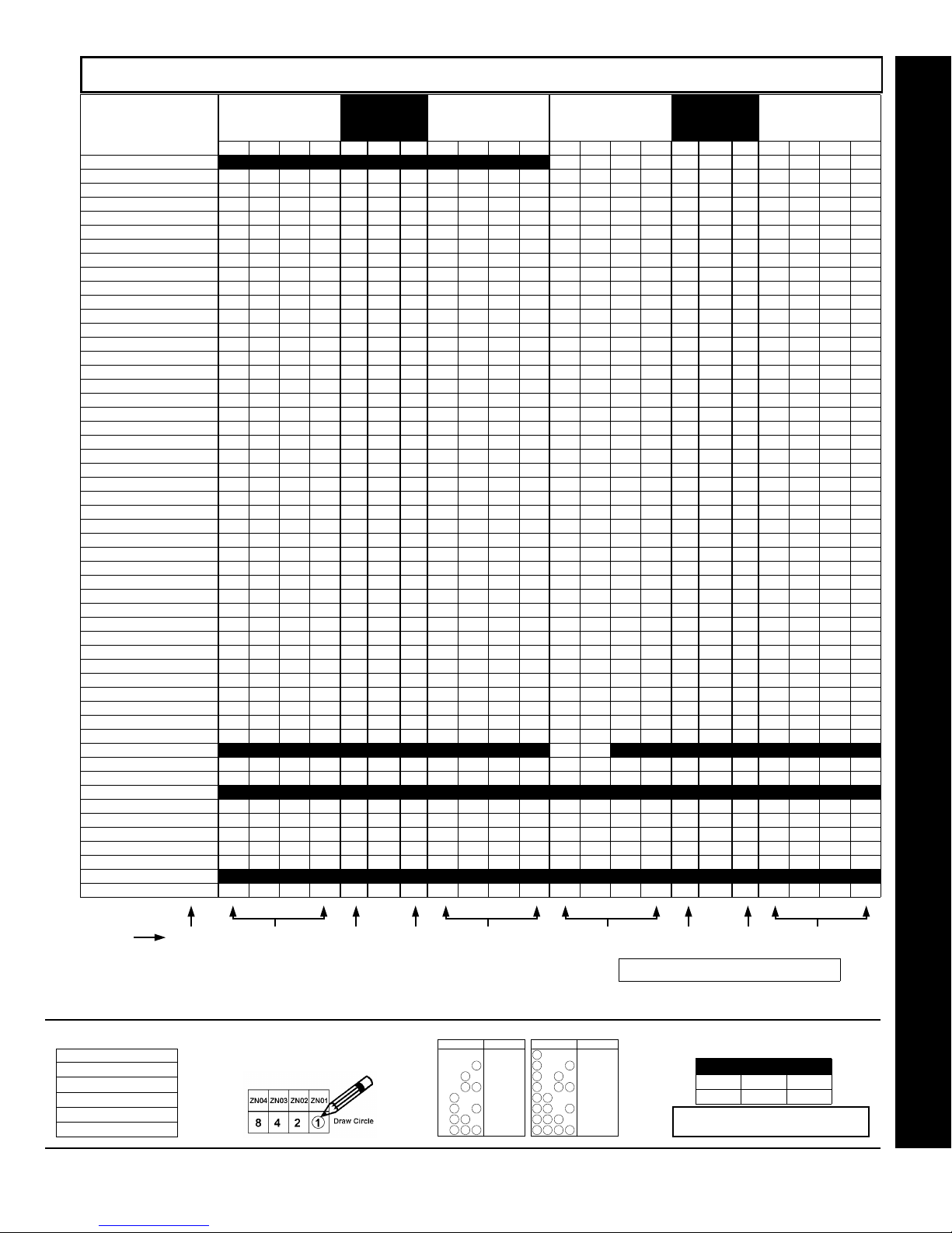
WI1387 7/05
ZONE OPTIONS - ZONES 1 TO 16 (ADDRESS 0900-1016)
See steps listed at
bottom of page
When the Easy Program Menu is used, these features are enabled by default.
Enabled when "Enable SIA CP-01 Features?" is activated (Answer "Yes" in the EZ Programming Menu).
Disabled when "Enable SIA CP-01 Features?" is activated (Answer "Yes" in the EZ Programming Menu). Disable Auto-Reset on non-fire zones for SIA CP-01 installations.
NOTE:
ZONE OPTIONS ZONES 13-16
LEFT DATA VALUES
50ms Loop Response
Priority 8 4 2 1 0965 8 4 2 1 8 4 2 1 0901 8 4 2 1
Priority with Bypass 8 4 2 1 0966 8 4 2 1 8 4 2 1 0902 8 4 2 1
Auto-Bypass 8 4 2 1 0967 8 4 2 1 8 4 2 1 0903 8 4 2 1
Selective Bypass 8 4 2 1 0968 8 4 2 1 8 4 2 1 0904 8 4 2 1
Keyswitch Arming 8 4 2 1 0969 8 4 2 1 8 4 2 1 0905 8 4 2 1
Auto-Bypass Re-entry 8 4 2 1 0970 8 4 2 1 8 4 2 1 0906 8 4 2 1
Pre-Alarm Warning 8 4 2 1 0971 8 4 2 1 8 4 2 1 0907 8 4 2 1
Never Arm 8 4 2 1 0972 8 4 2 1 8 4 2 1 0908 8 4 2 1
24-Hour Zone 8 4 2 1 0973 8 4 2 1 8 4 2 1 0909 8 4 2 1
Alarm Output 8 4 2 1 0974 8 4 2 1 8 4 2 1 0910 8 4 2 1
Pulsed Alarm Output 8 4 2 1 0975 8 4 2 1 8 4 2 1 0911 8 4 2 1
PGM1 Output 8 4 2 1 0976 8 4 2 1 8 4 2 1 0912 8 4 2 1
PGM2 Output 8 4 2 1 0977 8 4 2 1 8 4 2 1 0913 8 4 2 1
Entry/Exit 1 8 4 2 1 0978 8 4 2 1 8 4 2 1 0914 8 4 2 1
Entry/Exit 2 8 4 2 1 0979 8 4 2 1 8 4 2 1 0915 8 4 2 1
Exit/Entry Follower 8 4 2 1 0980 8 4 2 1 8 4 2 1 0916 8 4 2 1
Auto Reset 8 4 2 1 0981 8 4 2 1 8 4 2 1 0917 8 4 2 1
Swinger Shutdown 8 4 2 1 0982 8 4 2 1 8 4 2 1 0918 8 4 2 1
Chime 8 4 2 1 0983 8 4 2 1 8 4 2 1 0919 8 4 2 1
Abort Delay 8 4 2 1 0984 8 4 2 1 8 4 2 1 0920 8 4 2 1
Power-up Delay 8 4 2 1 0985 8 4 2 1 8 4 2 1 0921 8 4 2 1
Day Zone Open 8 4 2 1 0986 8 4 2 1 8 4 2 1 0922 8 4 2 1
Day Zone Short 8 4 2 1 0987 8 4 2 1 8 4 2 1 0923 8 4 2 1
Alarm on Day Zone 8 4 2 1 0988 8 4 2 1 8 4 2 1 0924 8 4 2 1
Alarm Telco 1 8 4 2 1 0989 8 4 2 1 8 4 2 1 0925 8 4 2 1
Alarm Restore 1 8 4 2 1 0990 8 4 2 1 8 4 2 1 0926 8 4 2 1
Trouble Telco 1 8 4 2 1 0991 8 4 2 1 8 4 2 1 0927 8 4 2 1
Trouble Restore 1 8 4 2 1 0992 8 4 2 1 8 4 2 1 0928 8 4 2 1
Alarm Telco 3 8 4 2 1 0993 8 4 2 1 8 4 2 1 0929 8 4 2 1
Alarm Restore 3 8 4 2 1 0994 8 4 2 1 8 4 2 1 0930 8 4 2 1
Trouble Telco 3 8 4 2 1 0995 8 4 2 1 8 4 2 1 0931 8 4 2 1
Trouble Restore 3 8 4 2 1 0996 8 4 2 1 8 4 2 1 0932 8 4 2 1
No EOL Resistor 8 4 2 1 0997 8 4 2 1 8 4 2 1 0933 8 4 2 1
Trouble on Open 8 4 2 1 0998 8 4 2 1 8 4 2 1 0934 8 4 2 1
Trouble on Short 8 4 2 1 0999 8 4 2 1 8 4 2 1 0935 8 4 2 1
Zone Area 1 8 4 2 1 1000 8 4 2 1 8 4 2 1 0936 8 4 2 1
Zone Area 2 8 4 2 1 1001 8 4 2 1 8 4 2 1 0937 8 4 2 1
Zone Area 3 8 4 2 1 1002 8 4 2 1 8 4 2 1 0938 8 4 2 1
Zone Area 4 8 4 2 1 1003 8 4 2 1 8 4 2 1 0939 8 4 2 1
Interior (Stay) Bypass 8 4 2 1 1004 8 4 2 1 8 4 2 1 0940 8 4 2 1
Keypad Sounder on Alarm 8 4 2 1 1005 8 4 2 1 8 4 2 1 0941 8 4 2 1
2-Wire Smoke Detectors
Fire (C) 8 4 2 1 1007 8 4 2 1 8 4 2 1 0943 8 4 2 1
Fire Alarm Verification
RESERVED 8 4 2 1 (•) 1009 (•) 8 4 2 1 8 4 2 1 (•) 0945 (•) 8 4 2 1
Zone ANDing Group 1 8 4 2 1 1010 8 4 2 1 8 4 2 1 0946 8 4 2 1
Zone ANDing Group 2 8 4 2 1 1011 8 4 2 1 8 4 2 1 0947 8 4 2 1
Zone ANDing Group 3 8 4 2 1 1012 8 4 2 1 8 4 2 1 0948 8 4 2 1
Zone ANDing Group 4 8 4 2 1 1013 8 4 2 1 8 4 2 1 0949 8 4 2 1
Sensor Watch 8 4 2 1 1014 8 4 2 1 8 4 2 1 0950 8 4 2 1
RESERVED 8 4 2 1 1015 8 4 2 1 8 4 2 1 0951 8 4 2 1
Chime 2 8 4 2 1 1016 8 4 2 1 8 4 2 1 0952 8 4 2 1
ZN16 ZN15 ZN14 ZN13 L ADDR R ZN12 ZN11 ZN10 ZN9 ZN8 ZN7 ZN6 ZN5 L ADDR R ZN4 ZN3 ZN2 ZN1
(A)
8 4 2 1 0964 8 4 2 1 8 4 2 1 0900 8 4 2 1
(B)
8 4 2 1 (•) 1006 (•) 8 4 2 1 8 4 2 1 0942 (•) 8 4 2 1
(C)
8 4 2 1 1008 8 4 2 1 8 4 2 1 0944 8 4 2 1
(CIRCLE
)
ADDRESS
ZONES 9-12
RIGHT DATA VALUES
(CIRCLE
)
ZONES 5-8
LEFT DATA VALUES
(CIRCLE
)
ADDRESS
RIGHT DATA VALUES
(CIRCLE
Step 1 Step 4 Step 4 Step 4 Step 4 Step 2 Step 2 Step 2 Step 2
For notes (A), (B) and (C), see next page.
(Address Location 0942 can only be programmed as “blank (•) blank (•)”, “4 blank (•)”, “8 blank (•)” or “C blank (•)”.
Page 45
ZONES 1-4
)
Direct Address Program Mode
1. Select the desired zone option.
ZONE OPTIONS
50ms Loop Response
Priority
2. Enable desired options for each zone
by drawing a circle around its
corresponding binary data value. NOTE:
s
No circle = feature disabled.
Priority with Bypass
Auto-Bypass
Selective Bypass
L
NAPCO Security Systems
3. Search table below for data entry. 4. Enter data in address locations (left and right
DIGIT VALUE DATA ENTRY
4821
4821
4821
8124
4821
4821
4821
4821
Blank (.)
1
2
3
4
5
6
7
X
DIGIT VALUE DATA ENTRY
8
421
421
8
8
421
8
8
4 21
8
4 21
8
4 2 1
8
4 2 1
8
9
0
B
124
C
D
E
F
digits). Press [Enter] or [ON/OFF] to save.
ADDRESS LOCATION
L ADDR R
blank (•) 0490 1
NOTE: Dark shaded boxes = option not available.
See Direct Address Programming Example page 22.
GEM-P1664EX Programming Instructions
Page 46
Page 46
ZONE OPTIONS - ZONES 17 TO 32 (ADDRESS 1029-1144)
Direct Address Program Mode
See Steps listed at
bottom of page 44
When the Easy Program Menu is used, these features are enabled by default.
Enabled when "Enable SIA CP-01 Features?" is activated (Answer "Yes" in the EZ Programming Menu).
Disabled when "Enable SIA CP-01 Features?" is activated (Answer "Yes" in the EZ Programming Menu). Disable Auto-Reset on non-fire zones for SIA CP-01 installations.
ZONE OPTIONS ZONES 29-32
Priority 8 4 2 1 1093 8 4 2 1 8 4 2 1 1029 8 4 2 1
Priority with Bypass 8 4 2 1 1094 8 4 2 1 8 4 2 1 1030 8 4 2 1
Auto-Bypass 8 4 2 1 1095 8 4 2 1 8 4 2 1 1031 8 4 2 1
Selective Bypass 8 4 2 1 1096 8 4 2 1 8 4 2 1 1032 8 4 2 1
Keyswitch Arming 8 4 2 1 1097 8 4 2 1 8 4 2 1 1033 8 4 2 1
Auto-Bypass Re-entry 8 4 2 1 1098 8 4 2 1 8 4 2 1 1034 8 4 2 1
Pre-Alarm Warning 8 4 2 1 1099 8 4 2 1 8 4 2 1 1035 8 4 2 1
Never Arm 8 4 2 1 1100 8 4 2 1 8 4 2 1 1036 8 4 2 1
24-Hour Zone 8 4 2 1 1101 8 4 2 1 8 4 2 1 1037 8 4 2 1
Alarm Output 8 4 2 1 1102 8 4 2 1 8 4 2 1 1038 8 4 2 1
Pulsed Alarm Output 8 4 2 1 1103 8 4 2 1 8 4 2 1 1039 8 4 2 1
PGM1 Output 8 4 2 1 1104 8 4 2 1 8 4 2 1 1040 8 4 2 1
PGM2 Output 8 4 2 1 1105 8 4 2 1 8 4 2 1 1041 8 4 2 1
Entry/Exit 1 8 4 2 1 1106 8 4 2 1 8 4 2 1 1042 8 4 2 1
Entry/Exit 2 8 4 2 1 1107 8 4 2 1 8 4 2 1 1043 8 4 2 1
Exit/Entry Follower 8 4 2 1 1108 8 4 2 1 8 4 2 1 1044 8 4 2 1
Auto Reset 8 4 2 1 1109 8 4 2 1 8 4 2 1 1045 8 4 2 1
Swinger Shutdown 8 4 2 1 1110 8 4 2 1 8 4 2 1 1046 8 4 2 1
Chime 8 4 2 1 1111 8 4 2 1 8 4 2 1 1047 8 4 2 1
Abort Delay 8 4 2 1 1112 8 4 2 1 8 4 2 1 1048 8 4 2 1
Power-up Delay 8 4 2 1 1113 8 4 2 1 8 4 2 1 1049 8 4 2 1
Day Zone Open 8 4 2 1 1114 8 4 2 1 8 4 2 1 1050 8 4 2 1
Day Zone Short 8 4 2 1 1115 8 4 2 1 8 4 2 1 1051 8 4 2 1
Alarm on Day Zone 8 4 2 1 1116 8 4 2 1 8 4 2 1 1052 8 4 2 1
Alarm Telco 1 8 4 2 1 1117 8 4 2 1 8 4 2 1 1053 8 4 2 1
Alarm Restore 1 8 4 2 1 1118 8 4 2 1 8 4 2 1 1054 8 4 2 1
Trouble Telco 1 8 4 2 1 1119 8 4 2 1 8 4 2 1 1055 8 4 2 1
Trouble Restore 1 8 4 2 1 1120 8 4 2 1 8 4 2 1 1056 8 4 2 1
Alarm Telco 3 8 4 2 1 1121 8 4 2 1 8 4 2 1 1057 8 4 2 1
Alarm Restore 3 8 4 2 1 1122 8 4 2 1 8 4 2 1 1058 8 4 2 1
Trouble Telco 3 8 4 2 1 1123 8 4 2 1 8 4 2 1 1059 8 4 2 1
Trouble Restore 3 8 4 2 1 1124 8 4 2 1 8 4 2 1 1060 8 4 2 1
No EOL Resistor 8 4 2 1 1125 8 4 2 1 8 4 2 1 1061 8 4 2 1
Trouble on Open 8 4 2 1 1126 8 4 2 1 8 4 2 1 1062 8 4 2 1
Trouble on Short 8 4 2 1 1127 8 4 2 1 8 4 2 1 1063 8 4 2 1
Zone Area 1 8 4 2 1 1128 8 4 2 1 8 4 2 1 1064 8 4 2 1
Zone Area 2 8 4 2 1 1129 8 4 2 1 8 4 2 1 1065 8 4 2 1
Zone Area 3 8 4 2 1 1130 8 4 2 1 8 4 2 1 1066 8 4 2 1
Zone Area 4 8 4 2 1 1131 8 4 2 1 8 4 2 1 1067 8 4 2 1
Interior (Stay) Bypass 8 4 2 1 1132 8 4 2 1 8 4 2 1 1068 8 4 2 1
Keypad Sounder on Alarm 8 4 2 1 1133 8 4 2 1 8 4 2 1 1069 8 4 2 1
Fire (C) 8 4 2 1 1135 8 4 2 1 8 4 2 1 1071 8 4 2 1
Fire Alarm Verification
Zone ANDing Group 1 8 4 2 1 1138 8 4 2 1 8 4 2 1 1074 8 4 2 1
Zone ANDing Group 2 8 4 2 1 1139 8 4 2 1 8 4 2 1 1075 8 4 2 1
Zone ANDing Group 3 8 4 2 1 1140 8 4 2 1 8 4 2 1 1076 8 4 2 1
Zone ANDing Group 4 8 4 2 1 1141 8 4 2 1 8 4 2 1 1077 8 4 2 1
Sensor Watch 8 4 2 1 1142 8 4 2 1 8 4 2 1 1078 8 4 2 1
RESERVED 8 4 2 1 1143 8 4 2 1 8 4 2 1 1079 8 4 2 1
Chime 2 8 4 2 1 1144 8 4 2 1 8 4 2 1 1080 8 4 2 1
LEFT DATA VALUES
(CIRCLE
)
ZN32 ZN31 ZN30 ZN29 L ADDR R ZN28 ZN27 ZN26 ZN25 ZN24 ZN23 ZN22 ZN21 L ADDR R ZN20 ZN19 ZN18 ZN17
(C)
8 4 2 1 1136 8 4 2 1 8 4 2 1 1072 8 4 2 1
ADDRESS
ZONES 25-28
RIGHT DATA VALUES
(CIRCLE
)
ZONES 21-24
LEFT DATA VALUES
(CIRCLE
)
ADDRESS
Step 1 Step 4 Step 4 Step 4 Step 4 Step 2 Step 2 Step 2 Step 2
WI1387 7/05
ZONES 17-20
RIGHT DATA VALUES
(CIRCLE
)
(A) 50ms Loop Response only available for zones 1-8.
NOTES:
(B) 2-wire Smoke Detectors only available for zones 7 & 8, and
(C) If Fire Alarm Verification is selected, then Fire must also be selected.
DEFAULTS:
The zone options indicated are automatically set after exiting the Easy Menu Driven Mode.
--Priority, Selective Bypass, Alarm Output, Auto Reset, Swinger Shutdown and Zone Area 1 are enabled for the total number of zones entered in “
--Alarm Telco 1 is enabled for the zone number(s) entered in “
--Entry/Exit 1 and Chime are enabled for the zone number(s) entered in “
--Exit/Entry Follow er and Interior Bypass are enabled for the zone number(s) entered in “
--Pulse Alarm Output is enabled for the zone number(s) entered in “
--Fire is enabled for the zone number(s) entered in “
--2-Wire Smoke Detector is enabled for the zone number(s) entered in “
GEM-P1664EX Programming Instructions
X
REPORT ALL ZONES TO CENTRAL ZONES? Y/N
FIRE ZONES ENTER ZONE #
FIRE ZONES ENTER ZONE #
must also be selected.
Fire
ENTRY/EXIT ZONES ENTER ZONE #
INTERIOR ZONES ENTER ZONE #
” or “
2-WIRE FIRE ZNS ENTER ZONE #
”.
2-WIRE FIRE ZNS ENTER ZONE #
”.
# OF ZONES IN AREA1 ENTER # ZONES
”.
”.
”.
”.
”.
L
NAPCO Security Systems
Page 47
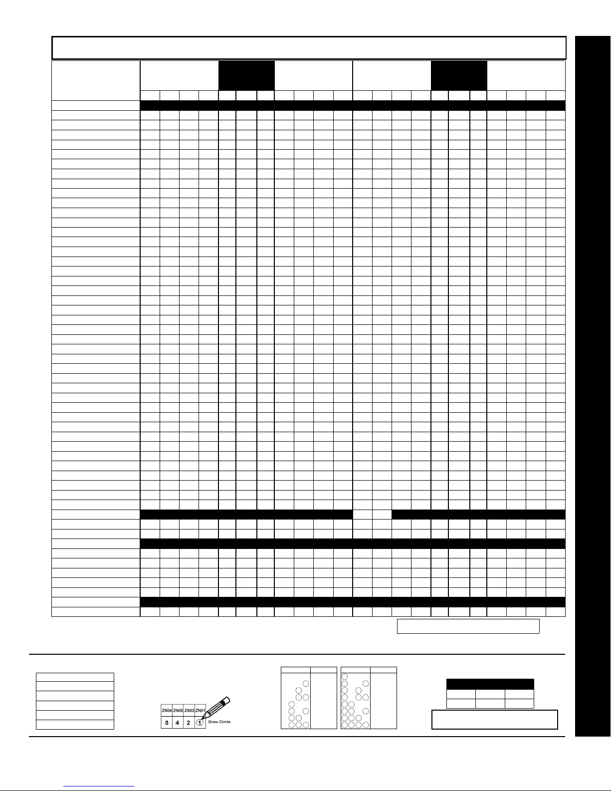
WI1387 7/05
ZONE OPTIONS - ZONES 33 TO 48 (ADDRESS 1157-1272)
When the Easy Program Menu is used, these features are enabled by default.
Enabled when "Enable SIA CP-01 Features?" is activated (Answer "Yes" in the EZ Programming Menu).
Disabled when "Enable SIA CP-01 Features?" is activated (Answer "Yes" in the EZ Programming Menu). Disable Auto-Reset on non-fire zones for SIA CP-01 installations.
1. Select the desired zone option.
50ms Loop Response
Priority
Priority with Bypass
Auto-Bypass
Selective Bypass
ZONE OPTIONS ZONES 45-48
LEFT DATA VALUES
50ms Loop Response
Priority 8 4 2 1 1221 8 4 2 1 8 4 2 1 1157 8 4 2 1
Priority with Bypass 8 4 2 1 1222 8 4 2 1 8 4 2 1 1158 8 4 2 1
Auto-Bypass 8 4 2 1 1223 8 4 2 1 8 4 2 1 1159 8 4 2 1
Selective Bypass 8 4 2 1 1224 8 4 2 1 8 4 2 1 1160 8 4 2 1
Keyswitch Arming 8 4 2 1 1225 8 4 2 1 8 4 2 1 1161 8 4 2 1
Auto-Bypass Re-entry 8 4 2 1 1226 8 4 2 1 8 4 2 1 1162 8 4 2 1
Pre-Alarm Warning 8 4 2 1 1227 8 4 2 1 8 4 2 1 1163 8 4 2 1
Never Arm 8 4 2 1 1228 8 4 2 1 8 4 2 1 1164 8 4 2 1
24-Hour Zone 8 4 2 1 1229 8 4 2 1 8 4 2 1 1165 8 4 2 1
Alarm Output 8 4 2 1 1230 8 4 2 1 8 4 2 1 1166 8 4 2 1
Pulsed Alarm Output 8 4 2 1 1231 8 4 2 1 8 4 2 1 1167 8 4 2 1
PGM1 Output 8 4 2 1 1232 8 4 2 1 8 4 2 1 1168 8 4 2 1
PGM2 Output 8 4 2 1 1233 8 4 2 1 8 4 2 1 1169 8 4 2 1
Entry/Exit 1 8 4 2 1 1234 8 4 2 1 8 4 2 1 1170 8 4 2 1
Entry/Exit 2 8 4 2 1 1235 8 4 2 1 8 4 2 1 1171 8 4 2 1
Exit/Entry Follower 8 4 2 1 1236 8 4 2 1 8 4 2 1 1172 8 4 2 1
Auto Reset 8 4 2 1 1237 8 4 2 1 8 4 2 1 1173 8 4 2 1
Swinger Shutdown 8 4 2 1 1238 8 4 2 1 8 4 2 1 1174 8 4 2 1
Chime 8 4 2 1 1239 8 4 2 1 8 4 2 1 1175 8 4 2 1
Abort Delay 8 4 2 1 1240 8 4 2 1 8 4 2 1 1176 8 4 2 1
Power-up Delay 8 4 2 1 1241 8 4 2 1 8 4 2 1 1177 8 4 2 1
Day Zone Open 8 4 2 1 1242 8 4 2 1 8 4 2 1 1178 8 4 2 1
Day Zone Short 8 4 2 1 1243 8 4 2 1 8 4 2 1 1179 8 4 2 1
Alarm on Day Zone 8 4 2 1 1244 8 4 2 1 8 4 2 1 1180 8 4 2 1
Alarm Telco 1 8 4 2 1 1245 8 4 2 1 8 4 2 1 1181 8 4 2 1
Alarm Restore 1 8 4 2 1 1246 8 4 2 1 8 4 2 1 1182 8 4 2 1
Trouble Telco 1 8 4 2 1 1247 8 4 2 1 8 4 2 1 1183 8 4 2 1
Trouble Restore 1 8 4 2 1 1248 8 4 2 1 8 4 2 1 1184 8 4 2 1
Alarm Telco 3 8 4 2 1 1249 8 4 2 1 8 4 2 1 1185 8 4 2 1
Alarm Restore 3 8 4 2 1 1250 8 4 2 1 8 4 2 1 1186 8 4 2 1
Trouble Telco 3 8 4 2 1 1251 8 4 2 1 8 4 2 1 1187 8 4 2 1
Trouble Restore 3 8 4 2 1 1252 8 4 2 1 8 4 2 1 1188 8 4 2 1
No EOL Resistor 8 4 2 1 1253 8 4 2 1 8 4 2 1 1189 8 4 2 1
Trouble on Open 8 4 2 1 1254 8 4 2 1 8 4 2 1 1190 8 4 2 1
Trouble on Short 8 4 2 1 1255 8 4 2 1 8 4 2 1 1191 8 4 2 1
Zone Area 1 8 4 2 1 1256 8 4 2 1 8 4 2 1 1192 8 4 2 1
Zone Area 2 8 4 2 1 1257 8 4 2 1 8 4 2 1 1193 8 4 2 1
Zone Area 3 8 4 2 1 1258 8 4 2 1 8 4 2 1 1194 8 4 2 1
Zone Area 4 8 4 2 1 1259 8 4 2 1 8 4 2 1 1195 8 4 2 1
Interior (Stay) Bypass 8 4 2 1 1260 8 4 2 1 8 4 2 1 1196 8 4 2 1
Keypad Sounder on Alarm 8 4 2 1 1261 8 4 2 1 8 4 2 1 1197 8 4 2 1
2-Wire Smoke Detectors
Fire (C) 8 4 2 1 1263 8 4 2 1 8 4 2 1 1199 8 4 2 1
Fire Alarm Verification
RESERVED 8 4 2 1 (•) 1265 (•) 8 4 2 1 8 4 2 1 (•) 1201 (•) 8 4 2 1
Zone ANDing Group 1 8 4 2 1 1266 8 4 2 1 8 4 2 1 1202 8 4 2 1
Zone ANDing Group 2 8 4 2 1 1267 8 4 2 1 8 4 2 1 1203 8 4 2 1
Zone ANDing Group 3 8 4 2 1 1268 8 4 2 1 8 4 2 1 1204 8 4 2 1
Zone ANDing Group 4 8 4 2 1 1269 8 4 2 1 8 4 2 1 1205 8 4 2 1
Sensor Watch 8 4 2 1 1270 8 4 2 1 8 4 2 1 1206 8 4 2 1
RESERVED 8 4 2 1 1271 8 4 2 1 8 4 2 1 1207 8 4 2 1
Chime 2 8 4 2 1 1272 8 4 2 1 8 4 2 1 1208 8 4 2 1
ZN48 ZN47 ZN46 ZN45 L ADDR R ZN44 ZN43 ZN42 ZN41 ZN40 ZN39 ZN38 ZN37 L ADDR R ZN36 ZN35 ZN34 ZN33
(A)
8 4 2 1 8 4 2 1 8 4 2 1 8 4 2 1
(B)
8 4 2 1 (•) 1262 (•) 8 4 2 1 8 4 2 1 1198 (•) 8 4 2 1
(C)
8 4 2 1 1264 8 4 2 1 8 4 2 1 1200 8 4 2 1
(CIRCLE
)
ADDRESS
ZONES 41-44
RIGHT DATA VALUES
(CIRCLE
)
ZONES 37-40
LEFT DATA VALUES
(CIRCLE
)
ADDRESS
ZONES 33-36
RIGHT DATA VALUES
(CIRCLE
For notes (A), (B) and (C), see next page.
3. Search table below for data entry. 4. Enter data in address locations (left and right
DIGIT VALUE DATA ENTRY
4821
4821
4821
8124
4821
4821
4821
4821
Blank (.)
1
2
3
4
5
6
7
DIGIT VALUE DATA ENTRY
8
421
421
8
8
421
8
8
4 21
8
4 21
8
4 2 1
8
4 2 1
8
9
0
B
124
C
D
E
F
digits). Press [Enter] or [ON/OFF] to save.
ADDRESS LOCATION
L ADDR R
blank (•) 0490 1
NOTE: Dark shaded boxes = option not available.
See Direct Address Programming Example page 22.
ZONE OPTIONS
2. Enable desired options for each zone
by drawing a circle around its
corresponding binary data value. NOTE:
s
No circle = feature disabled.
Page 47
)
Direct Address Program Mode
L
NAPCO Security Systems
GEM-P1664EX Programming Instructions
X
Page 48
Page 48
ZONE OPTIONS - ZONES 49 TO 64 (ADDRESS 1285-1400)
Direct Address Program Mode
See Steps listed at
bottom of page 44
When the Easy Program Menu is used, these features are enabled by default.
Enabled when "Enable SIA CP-01 Features?" is activated (Answer "Yes" in the EZ Programming Menu).
Disabled when "Enable SIA CP-01 Features?" is activated (Answer "Yes" in the EZ Programming Menu). Disable Auto-Reset on non-fire zones for SIA CP-01 installations.
ZONE OPTIONS ZONES 61-64
Priority 8 4 2 1 1349 8 4 2 1 8 4 2 1 1285 8 4 2 1
Priority with Bypass 8 4 2 1 1350 8 4 2 1 8 4 2 1 1286 8 4 2 1
Auto-Bypass 8 4 2 1 1351 8 4 2 1 8 4 2 1 1287 8 4 2 1
Selective Bypass 8 4 2 1 1352 8 4 2 1 8 4 2 1 1288 8 4 2 1
Keyswitch Arming 8 4 2 1 1353 8 4 2 1 8 4 2 1 1289 8 4 2 1
Auto-Bypass Re-entry 8 4 2 1 1354 8 4 2 1 8 4 2 1 1290 8 4 2 1
Pre-Alarm Warning 8 4 2 1 1355 8 4 2 1 8 4 2 1 1291 8 4 2 1
Never Arm 8 4 2 1 1356 8 4 2 1 8 4 2 1 1292 8 4 2 1
24-Hour Zone 8 4 2 1 1357 8 4 2 1 8 4 2 1 1293 8 4 2 1
Alarm Output 8 4 2 1 1358 8 4 2 1 8 4 2 1 1294 8 4 2 1
Pulsed Alarm Output 8 4 2 1 1359 8 4 2 1 8 4 2 1 1295 8 4 2 1
PGM1 Output 8 4 2 1 1360 8 4 2 1 8 4 2 1 1296 8 4 2 1
PGM2 Output 8 4 2 1 1361 8 4 2 1 8 4 2 1 1297 8 4 2 1
Entry/Exit 1 8 4 2 1 1362 8 4 2 1 8 4 2 1 1298 8 4 2 1
Entry/Exit 2 8 4 2 1 1363 8 4 2 1 8 4 2 1 1299 8 4 2 1
Exit/Entry Follower 8 4 2 1 1364 8 4 2 1 8 4 2 1 1300 8 4 2 1
Auto Reset 8 4 2 1 1365 8 4 2 1 8 4 2 1 1301 8 4 2 1
Swinger Shutdown 8 4 2 1 1366 8 4 2 1 8 4 2 1 1302 8 4 2 1
Chime 8 4 2 1 1367 8 4 2 1 8 4 2 1 1303 8 4 2 1
Abort Delay 8 4 2 1 1368 8 4 2 1 8 4 2 1 1304 8 4 2 1
Power-up Delay 8 4 2 1 1369 8 4 2 1 8 4 2 1 1305 8 4 2 1
Day Zone Open 8 4 2 1 1370 8 4 2 1 8 4 2 1 1306 8 4 2 1
Day Zone Short 8 4 2 1 1371 8 4 2 1 8 4 2 1 1307 8 4 2 1
Alarm on Day Zone 8 4 2 1 1372 8 4 2 1 8 4 2 1 1308 8 4 2 1
Alarm Telco 1 8 4 2 1 1373 8 4 2 1 8 4 2 1 1309 8 4 2 1
Alarm Restore 1 8 4 2 1 1374 8 4 2 1 8 4 2 1 1310 8 4 2 1
Trouble Telco 1 8 4 2 1 1375 8 4 2 1 8 4 2 1 1311 8 4 2 1
Trouble Restore 1 8 4 2 1 1376 8 4 2 1 8 4 2 1 1312 8 4 2 1
Alarm Telco 3 8 4 2 1 1377 8 4 2 1 8 4 2 1 1313 8 4 2 1
Alarm Restore 3 8 4 2 1 1378 8 4 2 1 8 4 2 1 1314 8 4 2 1
Trouble Telco 3 8 4 2 1 1379 8 4 2 1 8 4 2 1 1315 8 4 2 1
Trouble Restore 3 8 4 2 1 1380 8 4 2 1 8 4 2 1 1316 8 4 2 1
No EOL Resistor 8 4 2 1 1381 8 4 2 1 8 4 2 1 1317 8 4 2 1
Trouble on Open 8 4 2 1 1382 8 4 2 1 8 4 2 1 1318 8 4 2 1
Trouble on Short 8 4 2 1 1383 8 4 2 1 8 4 2 1 1319 8 4 2 1
Zone Area 1 8 4 2 1 1384 8 4 2 1 8 4 2 1 1320 8 4 2 1
Zone Area 2 8 4 2 1 1385 8 4 2 1 8 4 2 1 1321 8 4 2 1
Zone Area 3 8 4 2 1 1386 8 4 2 1 8 4 2 1 1322 8 4 2 1
Zone Area 4 8 4 2 1 1387 8 4 2 1 8 4 2 1 1323 8 4 2 1
Interior (Stay) Bypass 8 4 2 1 1388 8 4 2 1 8 4 2 1 1324 8 4 2 1
Keypad Sounder on Alarm 8 4 2 1 1389 8 4 2 1 8 4 2 1 1325 8 4 2 1
Fire (C) 8 4 2 1 1391 8 4 2 1 8 4 2 1 1327 8 4 2 1
Fire Alarm Verification
Zone ANDing Group 1 8 4 2 1 1394 8 4 2 1 8 4 2 1 1330 8 4 2 1
Zone ANDing Group 2 8 4 2 1 1395 8 4 2 1 8 4 2 1 1331 8 4 2 1
Zone ANDing Group 3 8 4 2 1 1396 8 4 2 1 8 4 2 1 1332 8 4 2 1
Zone ANDing Group 4 8 4 2 1 1397 8 4 2 1 8 4 2 1 1333 8 4 2 1
Sensor Watch 8 4 2 1 1398 8 4 2 1 8 4 2 1 1334 8 4 2 1
RESERVED 8 4 2 1 1399 8 4 2 1 8 4 2 1 1335 8 4 2 1
Chime 2 8 4 2 1 1400 8 4 2 1 8 4 2 1 1336 8 4 2 1
LEFT DATA VALUES
(CIRCLE
)
ZN64 ZN63 ZN62 ZN61 L ADDR R ZN60 ZN59 ZN58 ZN57 ZN56 ZN55 ZN54 ZN53 L ADDR R ZN52 ZN51 ZN50 ZN49
(C)
8 4 2 1 1392 8 4 2 1 8 4 2 1 1328 8 4 2 1
ADDRESS
ZONES 57-60
RIGHT DATA VALUES
(CIRCLE
)
ZONES 53-56
LEFT DATA VALUES
(CIRCLE
)
ADDRESS
Step 1 Step 4 Step 4 Step 4 Step 4 Step 2 Step 2 Step 2 Step 2
WI1387 7/05
ZONES 49-52
RIGHT DATA VALUES
(CIRCLE
)
(A) 50ms Loop Response only available for zones 1-8.
NOTES:
(B) 2-wire Smoke Detectors only available for zones 7 & 8, and
(C) If Fire Alarm Verification is selected, then Fire must also be selected.
DEFAULTS:
The zone options indicated are automatically set after exiting the Easy Menu Driven Mode.
--Priority, Selective Bypass, Alarm Output, Auto Reset, Swinger Shutdown and Zone Area 1 are enabled for the total number of zones entered in “
--Alarm Telco 1 is enabled for the zone number(s) entered in “
--Entry/Exit 1 and Chime are enabled for the zone number(s) entered in “
--Exit/Entry Follow er and Interior Bypass are enabled for the zone number(s) entered in “
--Pulse Alarm Output is enabled for the zone number(s) entered in “
--Fire is enabled for the zone number(s) entered in “
--2-Wire Smoke Detector is enabled for the zone number(s) entered in “
GEM-P1664EX Programming Instructions
X
REPORT ALL ZONES TO CENTRAL ZONES? Y/N
FIRE ZONES ENTER ZONE #
FIRE ZONES ENTER ZONE #
must also be selected.
Fire
ENTRY/EXIT ZONES ENTER ZONE #
INTERIOR ZONES ENTER ZONE #
” or “
2-WIRE FIRE ZNS ENTER ZONE #
”.
2-WIRE FIRE ZNS ENTER ZONE #
”.
# OF ZONES IN AREA1 ENTER # ZONES
”.
”.
”.
”.
”.
L
NAPCO Security Systems
Page 49
WI1387 7/05
EXTERNAL RELAY CONTROL (ADDRESS 1489-1608)
Page 49
ADDRESS 1489-1493 (RELAY EVENT 1)
1489 1490 1491 1492
RELAY # AREA Timeout Event ID COND.
L R L R L R L R L R
(•)
ADDRESS 1504-1508 (RELAY EVENT 4)
1504 1505 1506 1507
RELAY # AREA Timeout Event ID COND.
L R L R L R L R L R
(•)
ADDRESS 1519-1523 (RELAY EVENT 7)
1519 1520 1521 1522
RELAY # AREA Timeout Event ID COND.
L R L R L R L R L R
(•)
ADDRESS 1534-1538 (RELAY EVENT 10)
1534 1535 1536 1537
RELAY # AREA Timeout Event ID COND.
L R L R L R L R L R
(•)
(•)
(•)
(•)
(•)
1493
1508
1523
1538
ADDRESS 1494-1498 (RELAY EVENT 2)
1494 1495 1496 1497
RELAY # AREA Timeout Event ID COND.
L R L R L R L R L R
(•)
ADDRESS 1509-1513 (RELAY EVENT 5)
1509 1510 1511 1512
RELAY # AREA Timeout Event ID COND.
L R L R L R L R L R
(•)
ADDRESS 1524-1528 (RELAY EVENT 8)
1524 1525 1526 1527
RELAY # AREA Timeout Event ID COND.
L R L R L R L R L R
(•)
ADDRESS 1539-1543 (RELAY EVENT 11)
1539 1540 1541 1542
RELAY # AREA Timeout Event ID COND.
L R L R L R L R L R
(•)
(•)
(•)
(•)
(•)
1498
1513
1528
1543
ADDRESS 1499-1503 (RELAY EVENT 3)
1499 1500 1501 1502
RELAY # AREA Timeout Event ID COND.
L R L R L R L R L R
(•)
ADDRESS 1514-1518 (RELAY EVENT 6)
1514 1515 1516 1517
RELAY # AREA Timeout Event ID COND.
L R L R L R L R L R
(•)
ADDRESS 1529-1533 (RELAY EVENT 9)
1529 1530 1531 1532
RELAY # AREA Timeout Event ID COND.
L R L R L R L R L R
(•)
ADDRESS 1544-1548 (RELAY EVENT 12)
1544 1545 1546 1547
RELAY # AREA Timeout Event ID COND.
L R L R L R L R L R
(•)
(•)
(•)
(•)
(•)
1503
1518
1533
1548
Direct Address Program Mode
ADDRESS 1549-1553 (RELAY EVENT 13)
1549 1550 1551 1552
RELAY # AREA Timeout Event ID COND.
L R L R L R L R L R
(•)
ADDRESS 1564-1568 (RELAY EVENT 16)
1564 1565 1566 1567
RELAY # AREA Timeout Event ID COND.
L R L R L R L R L R
(•)
ADDRESS 1579-1583 (RELAY EVENT 19)
1579 1580 1581 1582
RELAY # AREA Timeout Event ID COND.
L R L R L R L R L R
(•)
ADDRESS 1594-1598 (RELAY EVENT 22)
1594 1595 1596 1597
RELAY # AREA Timeout Event ID COND.
L R L R L R L R L R
(•)
(•)
(•)
(•)
(•)
1553
1568
1583
1598
ADDRESS 1554-1558 (RELAY EVENT 14)
1554 1555 1556 1557
RELAY # AREA Timeout Event ID COND.
L R L R L R L R L R
(•)
ADDRESS 1569-1573 (RELAY EVENT 17)
1569 1570 1571 1572
RELAY # AREA Timeout Event ID COND.
L R L R L R L R L R
(•)
ADDRESS 1584-1588 (RELAY EVENT 20)
1584 1585 1586 1587
RELAY # AREA Timeout Event ID COND.
L R L R L R L R L R
(•)
ADDRESS 1599-1603 (RELAY EVENT 23)
1599 1600 1601 1602
RELAY # AREA Timeout Event ID COND.
L R L R L R L R L R
(•)
(•)
(•)
(•)
(•)
1558
1573
1588
1603
ADDRESS 1559-1563 (RELAY EVENT 15)
1559 1560 1561 1562
RELAY # AREA Timeout Event ID COND.
L R L R L R L R L R
(•)
ADDRESS 1574-1578 (RELAY EVENT 18)
1574 1575 1576 1577
RELAY # AREA Timeout Event ID COND.
L R L R L R L R L R
(•)
ADDRESS 1589-1593 (RELAY EVENT 21)
1589 1590 1591 1592
RELAY # AREA Timeout Event ID COND.
L R L R L R L R L R
(•)
ADDRESS 1604-1608 (RELAY EVENT 24)
1604 1605 1606 1607
RELAY # AREA Timeout Event ID COND.
L R L R L R L R L R
(•)
(•)
(•)
(•)
(•)
1563
1578
1593
1608
[Default = blank (•) blank (•) from address 1489-1608]
L
NAPCO Security Systems
CONTINUED ON
NEXT PAGE
GEM-P1664EX Programming Instructions
X
Page 50
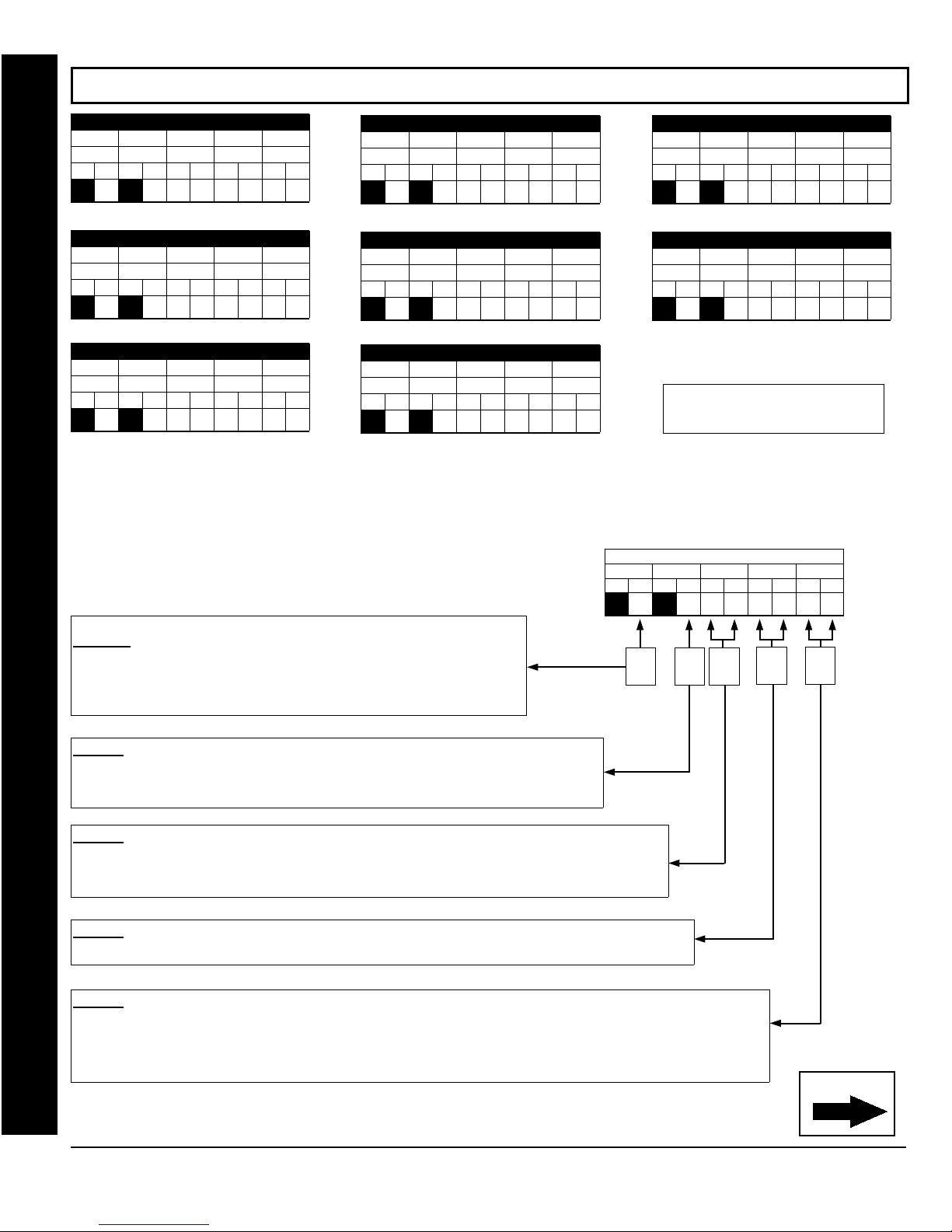
Page 50
WI1387 7/05
(CONT'D) EXTERNAL RELAY CONTROL (ADDRESS 1609-1648)
ADDRESS 1609-1613 (RELAY EVENT 25)
1609 1610 1611 1612
RELAY # AREA Timeout Event ID COND.
L R L R L R L R L R
(•)
ADDRESS 1624-1628 (RELAY EVENT 28)
1624 1625 1626 1627
RELAY # AREA Timeout Event ID COND.
L R L R L R L R L R
(•)
ADDRESS 1639-1643 (RELAY EVENT 31)
1639 1640 1641 1642
RELAY # AREA Timeout Event ID COND.
L R L R L R L R L R
(•)
To program, follow the 5 steps below:
(•)
(•)
(•)
To program, follow the 5 steps below:
STEP 1: RELAY # OPTIONS:
from Relay Module RM3008. Multiple events may be "mapped" to each relay,
up to a maximum of 16 events.
Select the relay number from Table 1 (shown on next page); enter in
corresponding right digit address location (left digit is not used).
1613
1628
1643
The GEM-P1664EX supports 8 external relays
ADDRESS 1614-1618 (RELAY EVENT 26)
1614 1615 1616 1617
RELAY # AREA Timeout Event ID COND.
L R L R L R L R L R
(•)
ADDRESS 1629-1633 (RELAY EVENT 29)
1629 1630 1631 1632
RELAY # AREA Timeout Event ID COND.
L R L R L R L R L R
(•)
ADDRESS 1644-1648 (RELAY EVENT 32)
1644 1645 1646 1647
RELAY # AREA Timeout Event ID COND.
L R L R L R L R L R
(•)
(•)
(•)
(•)
ADDRESS 1619-1623 (RELAY EVENT 27)
1618
1633
1648
1619 1620 1621 1622
RELAY # AREA Timeout Event ID COND.
L R L R L R L R L R
(•)
ADDRESS 1634-1638 (RELAY EVENT 30)
1634 1635 1636 1637
RELAY # AREA Timeout Event ID COND.
L R L R L R L R L R
(•)
[Default = blank (•) blank (•) from
address 1609-1648]
RELAY # AREA Timeout Event ID
L R L R L R L R L R
(•)
RELAY EVENT OPTIONS
Step
1
(•)
Step
2
(•)
(•)
COND.
Step
Step 4 Step
3
1623
1638
5
Direct Address Program Mode
STEP 2: AREA OPTIONS:
Area 2.
Select the area from
location (left digit is not used).
STEP 3: TIMEOUTS:
If Alarm Type (see next page) is selected for timeout in minutes or seconds, select the timeout from
(shown on next page) in minutes or seconds and enter in corresponding address location (left digit and
3
right digits). To choose seconds or minutes, see step 5A below. 254 is maximum entry.
STEP 4: EVENT ID CODES:
Select 2-digit Event ID from
Each relay event can be assigned to Area 1, Area 2 or both Area 1 &
(shown on next page); enter in corresponding right digit address
Table 2
Each relay event can be assigned a timeout depending on Alarm Type option.
Each relay event can be assigned any of the available event IDs from the table.
(see next page); enter in corresponding address locations (left and right digit).
Table 4
STEP 5: RELAY EVENT CONDITION OPTIONS:
condition; also, select a timeout type for each.
5A. Select Alarm Type and Timeout Type from Table 5A (shown on next page); enter in corresponding address location (left
digit).
5B. Select Activation from from Table 5B (shown on next page); enter in corresponding address location (right digit).
GEM-P1664EX Programming Instructions
X
Table
Each relay event can be assigned an alarm type; and an activation
L
NAPCO Security Systems
Continued
Page 51
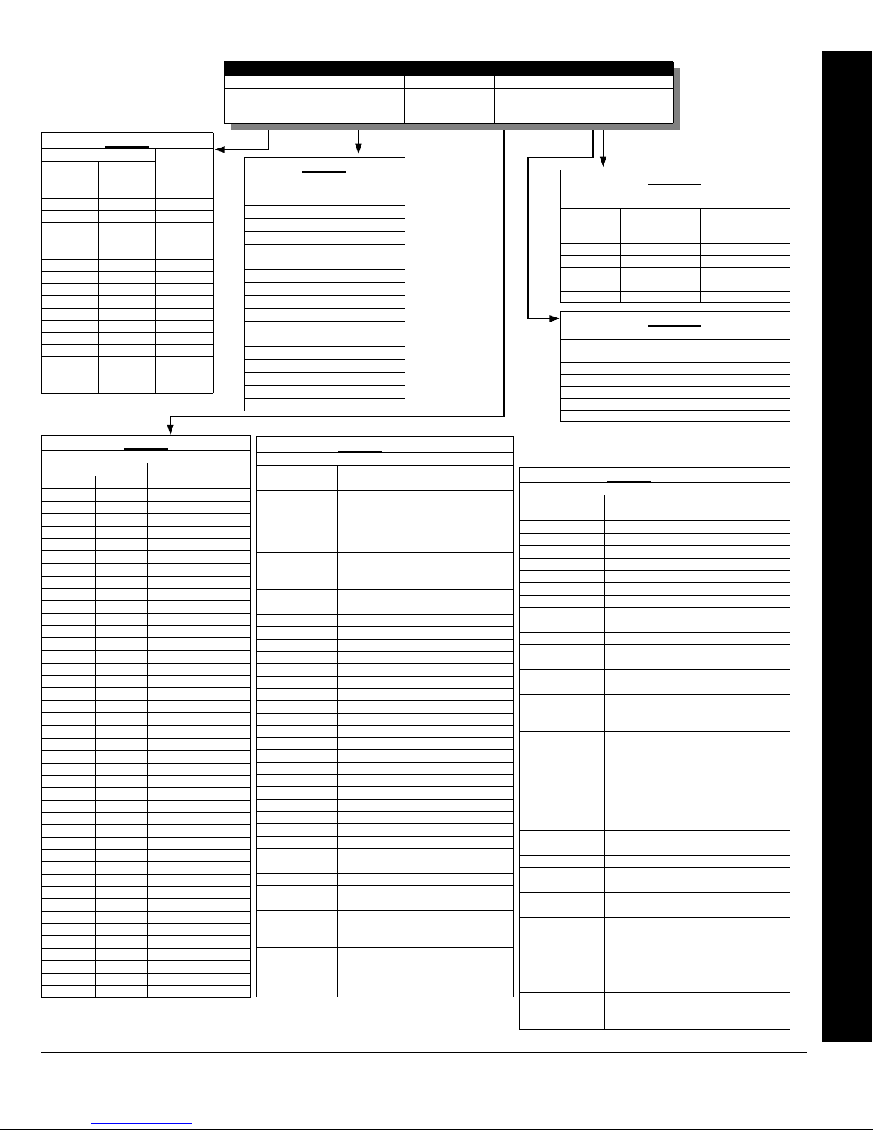
WI1387 7/05
Page 51
Table 1
DATA ENTRY
Left
Nibble
blank (•) blank (•) NONE
blank (•) 1 1
blank (•) 2 2
blank (•) 3 3
blank (•) 4 4
blank (•) 5 5
blank (•) 6 6
blank (•) 7 7
blank (•) 8 8
blank (•) 9 9
blank (•) 0 10
blank (•) B 11
blank (•) C 12
blank (•) D 13
blank (•) E 14
blank (•) F 15
1 blank (•) 16
Right
Nibble
RELAY #
Table 4
DATA ENTRIES OPTION
LEFT RIGHT
blank (•) blank (•) Area 1 Arm
blank (•) 1 Area 2 Arm
blank (•) 2 Area 3 Arm
blank (•) 3 Area 4 Arm
blank (•) 8 Zone 1
blank (•) 9 Zone 2
blank (•) 0 Zone 3
blank (•) B Zone 4
blank (•) C Zone 5
blank (•) D Zone 6
blank (•) E Zone 7
blank (•) F Zone 8
EVENT ID CODES
1 blank (•) Zone 9
1 1 Zone 10
1 2 Zone 11
1 3 Zone 12
1 4 Zone 13
1 5 Zone 14
1 6 Zone 15
1 7 Zone 16
1 8 Zone 17
1 9 Zone 18
1 0 Zone 19
1 B Zone 20
1 C Zone 21
1 D Zone 22
1 E Zone 23
1 F Zone 24
2 blank (•) Zone 25
2 1 Zone 26
2 2 Zone 27
2 3 Zone 28
2 4 Zone 29
2 5 Zone 30
2 6 Zone 31
2 7 Zone 32
2 8 Zone 33
2 9 Zone 34
2 0 Zone 35
2 B Zone 36
2 C Zone 37
RELAY # AREA TIMEOUT EVENT ID COND.
See
Table 1 below
Table 2 below
(right nibble)
RELAY EVENT OPTIONS
See
Enter a Time
period, in seconds
or minutes
See
Table 4 below
Tables 5A & 5B
Table 2
DATA
ENTRY
blank (•) NONE
TURN OFF ON AREA
DISARM
1 Area 1
2 Area 2
3 Area 1 & Area 2
4 Area 3
5 Area 1 & Area 3
6 Area 2 & Area 3
7 Areas 1, 2 & 3
8 Area 4
9 Area 1 & Area 4
0 Area 2 & Area 4
B Areas 1, 2 & 4
C Areas 3 & 4
D Areas 1, 3 & 4
E Areas 2, 3 & 4
F Areas 1-4
LEFT DATA
ENTRIES
blank (•) Burglary Minutes
1 Fire Minutes
4 Day Zone Minutes
8 Burglary Seconds
9 Fire Seconds
C Day Zone Seconds
RELAY EVENT ACTIVATION CONDITIONS
RIGHT DATA
ENTRIES
1 Alarm
2 Restore
3 Trouble
4 Trouble Restore
5 Follow Zone
Table 4 (cont'd)
DATA ENTRIES OPTION
LEFT RIGHT
2 D Zone 38
2 E Zone 39
2 F Zone 40
3 blank (•) Zone 41
3 1 Zone 42
3 2 Zone 43
3 3 Zone 44
3 4 Zone 45
3 5 Zone 46
3 6 Zone 47
3 7 Zone 48
3 8 Zone 49
3 9 Zone 50
3 0 Zone 51
3 B Zone 52
3 C Zone 53
3 D Zone 54
3 E Zone 55
3 F Zone 56
4 blank (•) Zone 57
4 1 Zone 58
4 2 Zone 59
4 3 Zone 60
4 4 Zone 61
4 5 Zone 62
4 6 Zone 63
4 7 Zone 64
6 8 Area 1 KP Ambush
6 9 Area 1 KP Panic
6 0 Area 1 KP Fire
6 B Area 1 KP Aux
6 C Area 1 KP Tamper
6 D Area 1 Fail to Open
6 E Area 1 Fail to Close
7 blank (•) Area 2 KP Ambush
7 1 Area 2 KP Panic
7 2 Area 2 KP Fire
7 3 Area 2 KP Aux
7 4 Area 2 KP Tamper
7 5 Area 2 Fail to Open
7 6 Area 2 Fail to Close
EVENT ID CODES
DATA ENTRIES OPTION
LEFT RIGHT
7 8 Area 3 KP Ambush
7 9 Area 3 KP Panic
7 0 Area 3 KP Fire
7 B Area 3 KP Aux
7 C Area 3 KP Tamper
7 D Area 3 Fail to Open
7 E Area 3 Fail to Close
7 F Area 4 KP Ambush
8 1 Area 4 KP Panic
8 2 Area 4 KP Fire
8 3 Area 4 KP Aux
8 4 Area 4 KP Tamper
8 5 Area 4 Fail to Open
8 6 Area 4 Fail to Close
0 8 Test Timer
0 B Memory Fail
0 C Low Battery
0 D AC Fail
0 E EZM Tamper
0 F Alarm Supervisory
B 5 RF Receiver Trouble (Tamper/Fail)
B 6 Wireless TX Tamper
B 7 Wireless TX Trouble (LB/Supervisory)
C 8 Area 1 Arming AWAY
C 9 Area 2 Arming AWAY
C 0 Area 3 Arming AWAY
C B Area 4 Arming AWAY
D blank (•) Keypad Fail
D 1 EZM Fail
D 2 Quickloader Device Control
D 5 General System Alarm
D 8 Area 1 General System Alarm
D 9 Area 2 General System Alarm
D 0 Area 3 General System Alarm
D B Area 4 General System Alarm
F blank (•) Relay Control Group 1
F 1 Relay Control Group 2
F 8 Entry Rela y Area 1
F 9 Entry Rela y Area 2
F 0 Entry Rela y Area 3
F B Entry Relay Area 4
Table 4 (cont'd)
EVENT ID CODES
See
below
Table 5A
RELAY EVENT
ALARM TYPE OPTIONS
ALARM TYPE TIMEOUT TYPE
Table 5B
OPTIONS
Direct Address Program Mode
L
NAPCO Security Systems
GEM-P1664EX Programming Instructions
X
Page 52
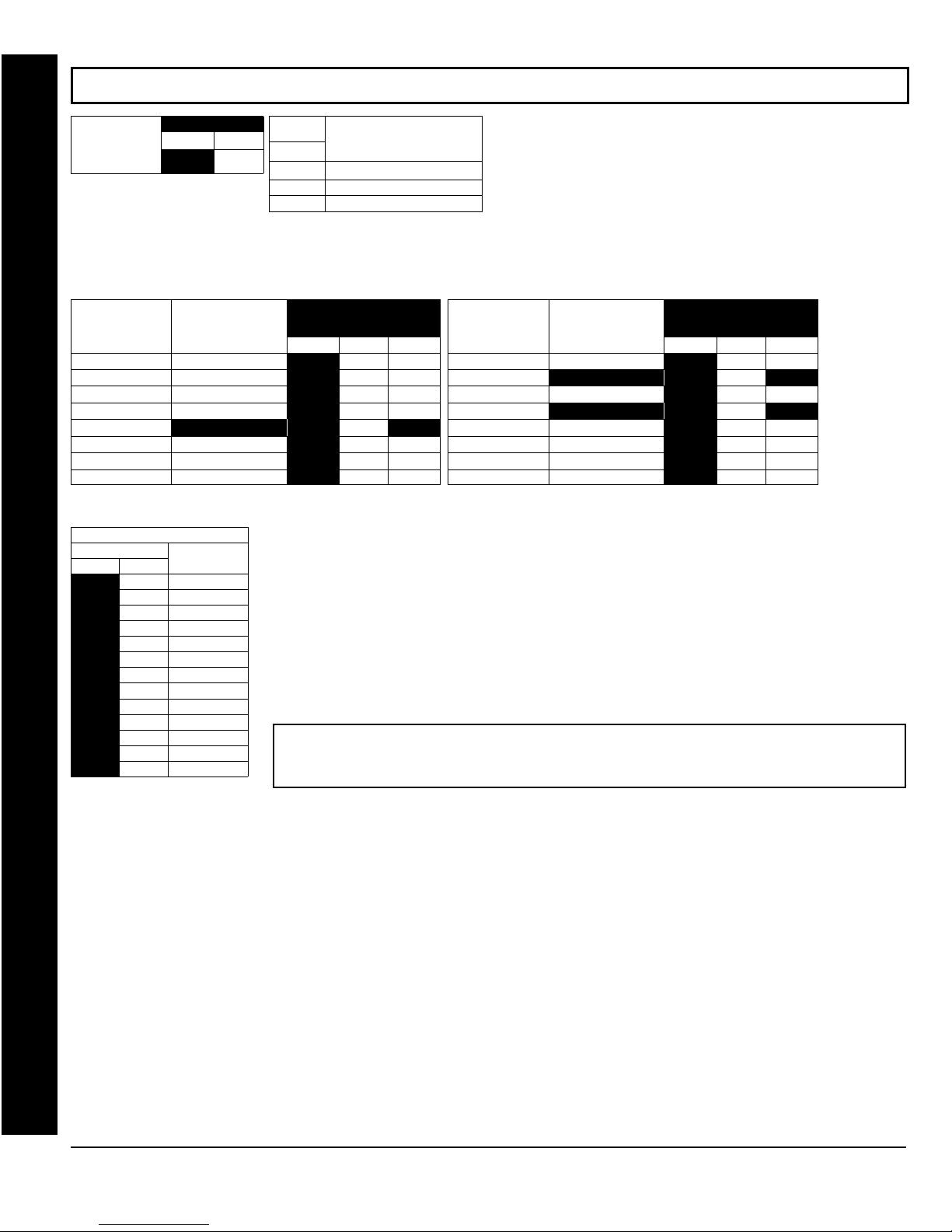
Page 52
WI1387 7/05
RF RECEIVER & SUPERVISORY TIMER OPTIONS (ADDRESS 2029-2044 & 2056)
Number of RF
Receivers blank (•)
Default for Number of Receivers
depends on Easy Menu Question for
RF Transmitters.
RF SUPERVISORY
TIMER
Type 0 Window/Door, 2 Pt. blank (•) 2029
Type 1 Window/Door, 2 Pt.
Type 2 Window/Door, 2 Pt.
Type 3 Window/Door, 2 Pt.
Type 4 RESERVED
Type 5 PIR
Type 6 PIR
Type 7 Smoke Detector
RF SUPERVISORY TIMERS
DATA ENTRIES
LEFT RIGHT
blank (•) 3 90 min.
blank (•) 4 120 min.
blank (•) 5 150 min.
blank (•) 6 180 min.
blank (•) 7 210 min.
blank (•) 8 240 min.
blank (•) 9 270 min.
blank (•) 0 300 min.
blank (•) B 330 min.
blank (•) C 360 min.
blank (•) D 390 min.
Direct Address Program Mode
blank (•) E 420 min.
blank (•) F 450 min.
ADDRESS 2056
LEFT RIGHT
RF TRANSMITTE R
DELAY
DATA
ENTRIES
RIGHT
blank (•) None
1 1
2 2
ADDRESS
2029-2036
LEFT ADDR RIGHT
blank (•) 2030
blank (•) 2031
blank (•) 2032
blank (•) 2033
blank (•) 2034
blank (•) 2035
blank (•) 2036
RF Receiver(s)
RF RECEIVERS: Up to 2 RF Receivers may be programmed.
1. Select the number of receivers from the table shown.
2. Enter in corresponding right digit address location shown
(left digit is not used).
3. Press U or D to save.
RF SUPERVISORY
TIMER
Type 8 Smoke Detector blank (•) 2037
Type 9 RESERVED
Type A Dual Tech.
Type B RESERVED
Type C Window/Door, 4 Pt.
Type D PIR
Type E Smoke Detector
Type F Napco Glass Break
RF TRANSMITTE R
LEFT ADDR RIGHT
blank (•) 2038
blank (•) 2039
blank (•) 2040
blank (•) 2041
blank (•) 2042
blank (•) 2043
blank (•) 2044
ADDRESS
2037-2044
[Default = blank (•) blank (•) from address 2029-2044]
RF SUPERVISORY TIMERS: RF Supervisory Timers may be programmed for each type of
transmitter used. A transmitter will send a transmission every time it is tripped, when there is NO
activity, the transmitter sends a status transmission about once an hour. If the receiver does NOT
receive ANY signal (a trip or a status) from a transmitter in the time specified for transmitter type, a
system trouble “
1. Select timer delay from the table shown. Timers are programmed in increments of 30 minutes
WIRELESS TROUBLE/E04-NN SERVICE
” will be displayed at the keypad.
each. Valid entries are [blank (•)3]-[blank (•)F], 90 minutes-450 minutes.
2. Enter in corresponding address locations above right digit only (left digit is not used).
3. Press U or D to save.
NOTE: These timers apply only to Supervised RF Transmitters (see RF Transmitters in Easy
Menu Driven Mode Programming).
GEM-P1664EX Programming Instructions
X
L
NAPCO Security Systems
Page 53
WI1387 7/05
CLEAR PROGRAM OPTIONS (ADDRESS 2285 & 2286)
Page 53
2285 XX
GEM-RP1CAe2 Keypad
2285 XX
GEM-RP2ASe2 Keypad
2286 XX
GEM-RP1CAe2 Keypad
2286 XX
GEM-RP2ASe2 Keypad
Clear Dealer Program (Erases Dealer Program)
This erases the dealer program. Use this feature to start a
customized default program. Program Data and System
Status Memory is erased where Scheduled Data and Zone
Descriptions are maintained.
Access address 2285, then press the
NOTE: Enter Easy Menu Driven Program Mode to program system again.
U button. Data entry is not allowed.
Cold Start (Erases Entire Program)
This erases the entire program including Dealer Program
by erasing Program Data, Zone Description Data and
System Status Data (similar to a new panel).
Access address 2286, then press the
NOTE: Some features (schedules) can only be programmed again with the
Downloading Software. NOTE: Some features (schedules) can only be
programmed again with the Downloading Software. If power fails, time and
date restarts at 00:00:00 and a date of 01-01-04 (January 1, 2004).
button. Data entry is not allowed.
U
Direct Address Program Mode
USER PROGRAM MODE
PRELIMINARY INFORMATION
The User Program Mode is covered in detail in the operating instructions for the keypad in use.
The Program Mode cannot be accessed while the communicator is transmitting except during the first three minutes after power-up.
After entering codes or data, press the save U button. Data will not be stored into memory unless this button is pressed.
If the keypad is in the Program Mode and no activity is detected for longer than 4 minutes, a steady tone will sound.
Press the C button to silence the sounder and exit the User Program Mode.
Use the R or A button to manually scroll the display at the end of each programming line.
ACCESSING USER PROGRAM MODE
1. Press
2. Press
3. Press
4. Press
EEEEEE
New Panel (Default User Code = 123)
Existing Panel (Any Code with User Program Option Enabled)
Q
P
C
Until “TURNON PROG Y/N” (GEM-RP2ASe2/GEM-K2AS) or “17” (GEM-RP3DGTL/GEM-K3DGTL or
GEM-RP4RFC/GEM-K4RF) appears on the LCD screen.
To Enter User Program Mode.
To Exit User Program Mode when finished.
R
L
NAPCO Security Systems
GEM-P1664EX Programming Instructions
X
Page 54
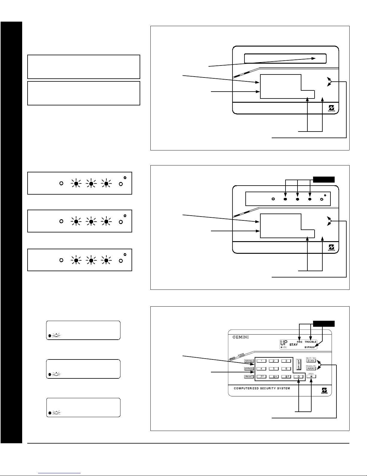
Page 54
WI1387 7/05
USER CODES
GEM-K2AS Keypad
USER01
GEM-K3DGTL Keypad
UP
0 I
INTERIOR
User Program Mode
INTERIOR
1
INTERIOR
User Code (Direct Entry)
123___
(Direct Entry)
FIRE/TBL SYS TBL
BYPASS
FIRE/TBL SYS TBL
BYPASS
User Number
FIRE/TBL SYS TBL CHIME
BYPASS
CHIME
CHIME
To Program User Codes
1. Enter 2-digit User Number
(01-64) directly using number
buttons (0-9).
2. Press the
3. Enter Code (1-6 digits) directly
using number buttons (0-9).
4. Press the
each code.
NOTE:
To continue press
To Program User Codes
1. Enter 2-digit User Number
(01-64) directly using number
buttons (0-9).
2. Press the
3. Enter Code (1-6 digits) directly
using number buttons (0-9).
4. Press the
each code.
NOTE:
To continue press
Press
Press
R
U
R
U
GEMINI
User01
STATUS
ARMED
button.
button to save
G
0
R
1 2
B 4 5 6
C 7 8 9 0
COMPUTERIZED SECURITY SYSTEM
button to clear character at cursor.
P
or
Q
button.
3
U
Programming User Codes with GEM-K2AS Keypad
GEMINI
UP
button.
button to save
G
0
INTERIOR
STATUS
ARMED
R 1 2 3
B 4 5 6
C
7 8 9 0
COMPUTERIZED SECURITY SYSTEM
button to clear character at cursor.
P
or
Q
button.
BYPASS
FIRE/TBL SYS TBL
U
NEXT/YES
P
PRIOR/NO
Q
AREA
G
Flashing
CHIME
NEXT/YES
P
PRIOR/NO
Q
AREA
G
Programming User Codes with GEM-K3DGTL Keypad
User Program Mode: Accessing Program Mode & User Codes
GEM-K4RF Keypad
UP
01
-
User Code (Direct Entry)
FIRE
User Program Mode
FIRE
User Number
FIRE
TROUBLE
BYPASS
TROUBLE
BYPASS
TROUBLE
BYPASS
CHIME
CHIME
CHIME
To Program User Codes
1. Enter 2-digit User Number
(01-64) directly using number
buttons (0-9).
2. Press the
3. Enter Code (1-6 digits) directly
using number buttons (0-9).
4. Press the
each code.
Press
NOTE:
To continue press P or Q button.
button.
R
button to save
U
G
0
button to clear character at cursor.
Flashing
Programming User Codes with GEM-K4RF Keypad
GEM-P1664EX Programming Instructions
X
L
NAPCO Security Systems
Page 55
WI1387 7/05
Page 55
KEYPAD CONFIGURATION MODE
This section will focus on configuring the GEM-RP2ASe2/GEM-K2AS, GEM-RP3DGTL/GEM-K3DGTL and GEMRP4RFC/GEM-K4RF Keypads. For ease of programming, it is recommended that a GEM-RP1CAe2 or a GEM-K1CA
be selected (see WI1386 for Programming Instructions using the GEM-RP1CAe2 or GEM-K1CA keypads).
KEYPAD INSTALLATION
Each keypad must be assigned an address number (1–7) and each requires its own configuration procedure (see
CONFIGURING THE KEYPADS, which follows, and DIRECT ADDRESS KEYPAD AREA OPTIONS). At least 1
keypad must be used; only 1 is required for a single-area Commercial Burglary installation.
GEM-RP2ASe2/GEM-K2AS - are utility LCD keypads combining several preset LCD words with a limited
message line.
automatically.
CONFIGURING THE KEYPADS
NOTE:
Configuring the GEM-RP2ASe2/GEM-K2AS, GEM-RP3DGTL/GEM-K3DGTL and GEMRP4RFC/GEM-K4RF Keypads
Up to 7 GEM-RP2ASe2/GEM-K2AS, GEM-RP3DGTL/GEM-K3DGTL and/or GEM-RP4RFC/GEM-K4RF keypads may
be connected to the panel (Keypads 1–7). Each must be configured for a keypad address. In addition, the keypad may
be configured to disable (a) touchpad backlight; (b) LCD backlight; and
(c) entry sounder. Keypads are configured by the proper selection of
jumpers. Refer to the label on the circuit board insulation paper for
jumper locations and a summary of settings.
KEYPAD ADDRESS
If more than one keypad is installed:
Each must be assigned a unique address (that is, no two keypads
may be numbered alike).
Keypads must be addressed consecutively (that is, missing
numbers are not permitted).
Assign the keypad address number by selecting Jumpers J1–3 in
accordance with the table at right.
TOUCHPAD BACK LIGHT
Cut Jumper A to disable touch pad backlighting to conserve 11mA standby current.
LCD BACKLIGHT
Cut Jumper B to disable LCD backlighting.
DISABLE SOUNDER
Cut Jumper C to disable the sounder.
Due to space constraints, available messages are abbreviated and will scroll
KEYPAD
NUMBER
KEYPAD ADDRESS SETTING
1 2 3
OFF OFF
OFF
1
2
3 ON ON
4
5 ON
6
7 ON ON ON
or
ON
OFF
OFF OFF OFF
OFF
OFF
ON
OFF
OFF
ON
ON ON
PARK
STORE SPARE
JUMPER AT THIS
POSITION
Keypad Configuration Mode: Configuring the Keypads
L
NAPCO Security Systems
GEM-P1664EX Programming Instructions
X
Page 56

Page 56
ALPHABETICAL INDEX
2
24 HOUR ZONES IN AREA 1: EASY PROGRAM MENU, 7, 14,
15
24-HOUR ZONE--ZONE OPTION, 45, 46, 47, 48
2-WIRE FIRE ZONES: EASY PROGRAM MENU, 13
2-WIRE FIRE ZONES IN AREA 1: EASY PROGRAM MENU, 6
2-WIRE SMOKE DETECTORS--ZONE OPTION, 45, 47
3
3/1 WITH EXTENDED RESTORES (CS RECEIVER OPTIONS),
30
WI1387 7/05
8, 14, 15
AUTO RESET AFTER BURGLARY OUTPUT TIMEOUT
ADDRESS 1421, 28
AUTO RESET--ZONE OPTION, 45, 46, 47, 48
AUTO-BYPASS RE-ENTRY--ZONE OPTION, 45, 46, 47, 48
AUTO-BYPASS--ZONE OPTION, 45, 46, 47, 48
AUTOMATIC INTERIOR BYPASS/EASY EXIT ADDRESS 1424,
28
AUX 1/AUX 2 OPTIONS: EASY PROGRAM MENU, 11
AUX OUTPUT ACTIVATED ON ALARM ZONES: EASY
PROGRAM MENU, 14
AUX OUTPUT ACTIVATED ON ALARM ZONES: EASY
PROGRAM MENU, 7
AUXILIARY REPORTING OPTIONS ADDRESS 0701, 32
5
50 MS LOOP RESPONSE ZONES: EASY PROGRAM MENU,
14, 15
50MS LOOP RESPONSE--ZONE OPTION, 45, 47
A
ABORT DELAY ADDRESS 1417, 24
ABORT DELAY--ZONE OPTION, 45, 46, 47, 48
AC FAIL, 26
AC FAIL REPORT DELAY ADDRESS 1419, 24
ACCESS CONTROL ON PGM2 OUTPUT ADDRESS 1421, 28
ACCESSING DEALER PROGRAM MODE, 5
ADEMCO EXPRESS RECEIVER FORMAT, 16
ADEMCO POINT ID FORMAT, 30
ADEMCO POINT ID RECEIVER FORMAT, 16
ADEMCO SLOW FORMAT, 30
ADEMCO SLOW RECEIVER FORMAT, 16
ALARM ON DAY ZONE--ZONE OPTION, 45, 46, 47, 48
ALARM OUTPUT ADDRESS 0836, 26
ALARM OUTPUT ADDRESS 0857, 26
ALARM OUTPUT ADDRESS 0865, 26, 27
ALARM OUTPUT ADDRESS 0873, 27
ALARM OUTPUT SUPERV. REPORTING OPTIONS ADDRESS
0689, 32
ALARM OUTPUT TIMEOUT ADDRESS 1414, 25
ALARM OUTPUT--ZONE OPTION, 45, 46, 47, 48
ALARM RESTORE 1--ZONE OPTION, 45, 46, 47, 48
ALARM RESTORE 3--ZONE OPTION, 45, 46, 47, 48
ALARM RESTORE REPORTING OPTIONS ADDRESS 0670, 32
ALARM TELCO 1--ZONE OPTION, 45, 46, 47, 48
ALARM TELCO 3--ZONE OPTION, 45, 46, 47, 48
AMBUSH, 26, 27
AMBUSH (KEYPAD OPTIONS), 42
AMBUSH CODE, GLOBAL, 26
AMBUSH REPORTING OPTIONS ADDRESS 0698, 32
AREA 1 SYSTEM EVENT/TROUBLE, 26
AREA 2 SYSTEM EVENT/TROUBLE, 26
AREA 3 SYSTEM EVENT/TROUBLE, 27
AREA 4 SYSTEM EVENT/TROUBLE, 27
AREA ARMING OPTIONS (ADDRESS 1469-1472), 44
AREA BELL CONTROL OPTIONS (ADDRESS 1473-1476), 38
AREA BELL CONTROL OPTIONS (ADDRESS 1477-1480), 39
AREA BELL CONTROL OPTIONS (ADDRESS 1481-1484), 40
AREA BELL CONTROL OPTIONS (ADDRESS 1485-1488), 41
AREA OPTIONS: EASY PROGRAM MENU, 10
AUTO BELL TEST ON ARMING ADDRESS 1421, 28
AUTO BYPASS RE-ENTRY ZONES: EASY PROGRAM MENU,
B
BACKLIGHTING, 55
BACKUP REPORT ON TELCO 1 & 2 ADDRESS 0788, 32
BELL SUPERVISION, 26
BINARY TEMPERATURE VALUES, 43
BURGLARY OUTPUT TURNS OFF UPON DISARM, 38
C
CALLBACK METHOD, 4
CALLBACK TELEPHONE NUMBER ADDRESS 0526-0545, 25
CANCEL NEXT TEST TIMER ON ANY REPORT ADDRESS
0788, 32
CANCEL REPORTING OPTIONS ADDRESS 0681, 32
CENTRAL STATION RECEIVER 1 ACCOUNT NUMBER: EASY
PROGRAM MENU, 9, 16
CENTRAL STATION RECEIVER 1 FORMAT: EASY PROGRAM
MENU, 9, 16
CENTRAL STATION RECEIVER 1 TELEPHONE NUMBER: EASY
PROGRAM MENU, 8, 16
CHANGE PULSE OUTPUT TO TEMPORAL OUTPUT
ADDRESS 1422, 28
CHANGING OR CANCELING A CODE, 10, 17
CHIME 2 ZONES IN AREA 1: EASY PROGRAM MENU, 7, 14, 15
CHIME 2--ZONE OPTION, 45, 46, 47, 48
CHIME TIME ADDRESS 1418, 24
CHIME ZONES IN AREA 1: EASY PROGRAM MENU, 7, 14, 15
CHIME--ZONE OPTION, 45, 46, 47, 48
CHIRP OUTPUT ON KEYFOB ARM/DISARM ADDRESS 1422,
28
CLEAR DEALER PROGRAM (ERASES DEALER PROGRAM),
53
CLEAR PROGRAM, 19
CLEAR PROGRAM ADDRESS 2285, 12
CLEAR PROGRAM OPTIONS (ADDRESS 2285 & 2286), 53
CLOCK ADJUSTMENTS (ADDRESS 2281), 33
CLOCK SOURCE (INTERNAL PANEL) ADDRESS 2281, 33
CLOSING REPORT ONLY ON CONDITIONAL CLOSE
ADDRESS 1420, 28
CLOSING REPORTING OPTIONS ADDRESS 0678, 32
COLD START ADDRESS 2286, 12, 18
COLD START (ERASES ENTIRE PROGRAM), 53
CONDITIONAL CLOSE REPORTING OPTIONS ADDRESS
0680, 32
CONFIGURING THE KEYPADS, 55
CONTROL PANEL PROGRAMMING: INTRODUCTION, 4
CONTROL PANEL ZONES REPORT CODE, 34
CONVENTIONS USED IN THIS MANUAL, 23
CS AREA & SYSTEM REPORTING OPTIONS (ADDRESS 0785,
GEM-P1664EX Programming Instructions
X
L
NAPCO Security Systems
Page 57

WI1387 7/05
Page 57
ALPHABETICAL INDEX (CONT'D)
0786 & 0788), 32
CS RECEIVER 1 FORMAT: EASY PROGRAM MENU, 16
CS RECEIVER 1 FORMAT ADDRESS 0460, 30
CS RECEIVER 1 TELEPHONE NUMBER ADDRESS 0462-
0481, 30
CS RECEIVER 2 FORMAT ADDRESS 0482, 30
CS RECEIVER 2 TELEPHONE NUMBER ADDRESS 0484-
0503, 30
CS RECEIVER 3 FORMAT ADDRESS 0504, 30
CS RECEIVER 3 TELEPHONE NUMBER ADDRESS 0506-
0525, 30
CS RECEIVER OPTIONS (ADDRESS 0460-0525), 30
CS RECEIVER TELCO 1 OPTIONS ADDRESS 0461, 30
CS RECEIVER TELCO 2 OPTIONS ADDRESS 0483, 30
CS RECEIVER TELCO 3 OPTIONS ADDRESS 0505, 30
CS SUBSCRIBER ID OPTIONS (ADDRESS 0560-0667), 31
CS SYSTEM REPORT OPTIONS, 32
CS SYSTEM REPORTING OPTIONS (ADDRESS 0670-0705),
32
CS USER REPORTING OPTIONS (ADDRESS 0800-0817), 35
CS USER REPORTING OPTIONS (ADDRESS 0818-0835), 36
CS ZONE REPORTING OPTIONS (ADDRESS 0720-0783), 34
CUSTOMIZING A DEFAULT PROGRAM, 5
D
DAY ZONE OPEN--ZONE OPTION, 45, 46, 47, 48
DAY ZONE SHORT--ZONE OPTION, 45, 46, 47, 48
DCI FORMAT, 30
DCI RECEIVER FORMAT, 16
DEALER CODE, 18, 19; DEFAULT, 5; EASY PROGRAM MENU,
11
DEALER PROGRAM: PRELIMINARY INFORMATION, 5
DEALER PROGRAM CODE, 6
DEALER PROGRAM MODE, 4
DEFAULT DEALER CODE, 5
DEFAULT DEALER PROGRAM CODE, 13
DEFAULT PROGRAM: CUSTOMIZING, 5
DIGITAL DIALER RPT ENTER /EXIT TEST MODE ADDRESS
2053, 29
DIRECT ADDRESS PROGRAM MODE, 4
DIRECT ADDRESS PROGRAM MODE, 21; ACCESSING, 20
DISABLE [ON/OFF] AS EASY EXIT ADDRESS 2051, 29
DISABLE 2ND CALL ANS. MACHINE OVERRIDE ADDRESS
1424, 28
DISABLE AUTO DIAL TONE DETECT ADDRESS 0788, 32
DISABLE CALL WAITING ON 1ST ATTEMPT ADDRESS 2053,
29
DISABLE CALLBACK DOWNLOAD ADDRESS 1422, 28
DISABLE CLOSING REPORTS ADDRESS 0786, 32
DISABLE CODE REQUIRED FOR EZ BYPASS ADDRESS
1424, 28
DISABLE KEYPAD FUNCTION MODE DOWNLOAD ADDRESS
1422, 28
DISABLE KEYPAD INSTANT MODE ADDRESS 1421, 28
DISABLE OPENING REPORTS ADDRESS 0785, 32
DISABLE SOUNDER, 55
DISABLE SYSTEM TROUBLE AUDIBLE TIMEOUT ADDRESS
2051, 29
DISABLE WAIT FOR HANDSHAKE ON TRANSMIT ADDRESS
0788, 32
DISABLE WAIT FOR SILENCE (PAGER FORMAT) ADDRESS
0788, 32
DISABLE ZONE FAULT SCROLLING ADDRESS 1420, 28
DON'T CLEAR PGM2 OUTPUT WITH DISARM ADDRESS
1424, 28
DOWNLOAD/CALLBACK OPTIONS (ADDRESS 2059 & 0526-
0545), 25
DOWNLOADING FROM A COMPUTER, 4
DOWNLOADING FROM A COMPUTER, 4
E
EASY ARMING (KEYPAD OPTIONS), 42
EASY MENU DRIVEN PROGRAM MODE, 5
EASY MENU-DRIVEN PROGRAM MODE, 4
EASY PROGRAM MENU: GEM-RP2ASE2/GEM-K2AS KEYPAD,
6; GEM-RP3DGTL/GEM-K3DGTL AND GEM-RP4RFC/GEM-
K4RF KEYPAD, 13
ENABLE "K SERIES" STYLE KEYPADS ADDRESS 2051, 29
ENABLE 2-COUNT SWINGER SHUTDOWN ADDRESS 2054,
29
ENABLE ALARM OUTPUT ON TELCO FAIL ONLY WHEN
ARMED ADDRESS 1423, 28
ENABLE AUTOARM IF NOT CLOSED AT END OF WINDOW
ADDRESS 1420, 28
ENABLE BURG OUTPUT CHIRP ON KEYFOB?: EASY
PROGRAM MENU, 8, 14, 15
ENABLE CANCEL REPORT TO TELCO 3 ADDRESS 2051, 29
ENABLE CP-01 EGRESS TONES ONLY ADDRESS 2053, 29
ENABLE CP-01 LIMITS ADDRESS 2053, 29
ENABLE DAYLIGHT SAVING TIME ADDRESS 2281, 33
ENABLE DISPLAY TIME ON BLANKED KEYPADS ADDRESS
2054, 29
ENABLE EN501 GRADE 3 OPERATION ADDRESS 2054, 29
ENABLE EN501 USER CODE ACCESS LEVEL ADDRESS
2054, 29
ENABLE FOR NEGATIVE TEMPERATURE VALUE ADDRESS
1666-1667, 43
ENABLE GEM-PRINT MODULE ADDRESS 2051, 29
ENABLE GLOBAL AMBUSH CODE ADDRESS 1422, 28
ENABLE KEYPAD 1 ONLY PROGRAMMING ADDRESS 2053,
29
ENABLE KEYPAD BLANKING ADDRESS 2054, 29
ENABLE KEYPAD SET TIME/DATE MESSAGE ADDRESS
2051, 29
ENABLE KEYPAD TIME/DATE DISPLAY ADDRESS 1420, 28
ENABLE LINE-FAULT TEST ADDRESS 1423, 28
ENABLE LOCAL ALARM ON FIRST ZONE AND TRIP
ADDRESS 1421, 28
ENABLE LOOP SUPERVISION ADDRESS 1424, 28
ENABLE MANAGER'S MODE ADDRESS 1421, 28
ENABLE NO EOLR ZONES: EASY PROGRAM MENU, 8, 14, 15
ENABLE RESIDENTIAL FIRE ADDRESS 1422, 28
ENABLE SIA CP-01?: EASY PROGRAM MENU, 14, 15
ENABLE SIA CP1?: EASY PROGRAM MENU, 8
ENABLE TCP/IP COMMUNICATIONS ADDRESS 2054, 29
ENABLE TELCO LINE FAULT TEST?: EASY PROGRAM MENU,
8, 14, 15
ENABLE TEMPERATURE DISPLAY OPTION ADDRESS 1668,
43
ENABLE TEMPERATURE OPTIONS ADDRESS 1668, 43
ENABLE ZONE DOUBLING (ZONES 9-16) ADDRESS 1423, 28
ENABLE ZONE NUMBER ON PULSE ALARM (CS RECEIVER
OPTIONS), 30
ENTER USER CODES: EASY PROGRAM MENU, 9, 16
ENTRY DELAY 1 ADDRESS 0001, 24
ENTRY DELAY 2 ADDRESS 0002, 24
ENTRY/EXIT 1--ZONE OPTION, 45, 46, 47, 48
ENTRY/EXIT 2--ZONE OPTION, 45, 46, 47, 48
ERASE DEALER PROGRAM, 12, 18
ERASE ENTIRE PROGRAM, 12, 18
L
NAPCO Security Systems
GEM-P1664EX Programming Instructions
X
Page 58

Page 58
ALPHABETICAL INDEX (CONT'D)
WI1387 7/05
EXIT DEALER PROGRAM MODE, 12, 19
EXIT DELAY ADDRESS 0000, 24
EXIT TIME RESTART ADDRESS 2053, 29
EXIT/ENTRY FOLLOWER--ZONE OPTION, 45, 46, 47, 48
EXIT/ENTRY ZONES: EASY PROGRAM MEN U, 13
EXIT/ENTRY ZONES IN AREA 1: EASY PROGRAM MENU, 6
EXIT/ENTRY2 ZONES IN AREA 1: EASY PROGRAM MENU, 7,
14, 15
EXTERNAL RELAY CONTROL (ADDRESS 1489-1608), 49
EXTERNAL RELAY CONTROL (ADDRESS 1609-1648), 50
EZM GROUP OPTIONS (ADDRESS 1455-1468), 37
EZM TAMPER, 26
EZM TAMPER REPORTING OPTIONS ADDRESS 0688, 32
F
FAIL TO CLOSE, 26, 27
FAIL TO CLOSE REPORTING OPTIONS ADDRESS 0704, 32
FAIL TO OPEN, 26, 27
FAIL TO OPEN REPORTING OPTIONS ADDRESS 0703, 32
FBI 4/3/1 RECEIVER FORMAT, 16
FIRE ALARM VERIFICATION--ZONE OPTION, 45, 46, 47, 48
FIRE REPORTING OPTIONS ADDRESS 0700, 32
FIRE ZONES: EASY PROGRAM MENU, 13
FIRE ZONES IN AREA 1: EASY PROGRAM MENU, 6
FIRE--ZONE OPTION, 45, 46, 47, 48
FRANKLIN FAST RECEIVER FORMAT, 16
FRANKLIN SLOW FORMAT, 30
FRANKLIN SLOW RECEIVER FORMAT, 16
FUNCTION MODE, 4
G
GEM-P1664 WIRING DIAGRAM, 64
GENERAL PROGRAMMING STEPS, 23
GLOBAL AMBUSH CODE ADDRESS 2045, 26
GLOBAL SYSTEM EVENT/TROUBLE, 26
H
HANDSHAKE/KISSOFF 1400HZ (CS RECEIVER OPTIONS), 30
HANDSHAKE/KISSOFF 2300HZ (CS RECEIVER OPTIONS), 30
I
INCL. SEL./GRP. BYPASS IN COND. CLOSE /STATUS
ADDRESS 1420, 28
INHIBIT SYSTEM TROUBLE AUDIBLE AT KEYPAD ADDRESS
1423, 28
INTERIOR (STAY) BYPASS ZONES IN AREA 1: EASY PRO GRAM
MENU, 7
INTERIOR (STAY) BYPASS--ZONE OPTION, 45, 46, 47, 48
INTERIOR NORMALLY BYPASSED ADDRESS 1422, 28
INTERIOR ZONES: EASY PROGRAM MENU, 14, 15
K
K SERIES KEYPADS, 2
KEY FOB TRANSMITTERS, 18, 19
KEY FOB TRANSMITTERS AS ARM/DISARM & CONTROL
DEVICES: EASY PROGRAM MENU, 11
KEY FOB TRANSMITTERS AS ZONE INPUT DEVICES, 18, 19;
EASY PROGRAM MENU, 11
KEY FOB ZONE ASSIGNMENT, 18; EASY PROGRAM MENU,
11
KEYFOB LOW BATTERY, 26, 27
KEYFOB LOW BATTERY REPORTING OPTIONS ADDRESS
0705, 32
KEYPAD ADDRESS, 55
KEYPAD ADDRESS PROGRAM MODE DISPLAY, 21
KEYPAD AUX., 26, 27
KEYPAD AUX. (KEYPAD OPTIONS), 42
KEYPAD CONFIGURATION MODE, 55
KEYPAD FIRE, 26, 27
KEYPAD FIRE (KEYPAD OPTIONS), 42
KEYPAD INSTALLATION, 55
KEYPAD OPTIONS (ADDRESS 1425-1431, 1440-1446), 42
KEYPAD PANIC, 26, 27
KEYPAD PANIC (KEYPAD OPTIONS), 42
KEYPAD PROGRAMMING OVERVIEW, 20
KEYPAD SOUNDER ON ALARM ZONES: EASY PROGRAM
MENU, 7, 14
KEYPAD SOUNDER ON ALARM--ZONE OPTION, 45, 46, 47, 48
KEYPAD TAMPER, 26, 27
KEYPAD TYPE, 42
KEYPAD UNBLANKING TIME WINDOW ADDRESS 2060, 33
KEYSWITCH ARMING--ZONE OPTION, 45, 46, 47, 48
L
LCD BACKLIGHT, 55
LEADING DIGITS FOR PAGER FORMAT (1ST DIGIT)
ADDRESS 0546, 25
LEADING DIGITS FOR PAGER FORMAT (2ND DIGIT)
ADDRESS 0547, 25
LINE FREQUENCY--ENABLE 50HZ ADDRESS 2281, 33
LINE-FAULT TEST ONLY WHEN ARMED ADDRESS 1423, 28
LOCAL DOWNLOADING, 4
LOCAL OR CENTRAL STATION REPORTING SYSTEM: EASY
PROGRAM MENU, 6
LOCAL SYSTEM OR C.S. REPORTING SYSTEM: EASY
PROGRAM MENU, 13
LOW BATTERY, 26
LOW BATTERY REPORTING OPTIONS ADDRESS 0686, 32
LUG E15 AREA 1 ARMED AWAY ONLY ADDRESS 2052, 29
M
MAINTAINED KEYSWITCH ARMING ADDRESS 1421, 28
MEMORY FAIL REPORTING OPTIONS ADDRESS 0685, 32
MEMORY FAILURE, 26
MODEM CODES, 34
N
NEVER ARM--ZONE OPTION, 45, 46, 47, 48
NO EOL RESISTOR--ZONE OPTION, 45, 46, 47, 48
NO. RINGS BEFORE PICKUP ADDRESS 2059, 25
NUMBER OF KEYPADS: EASY PROGRAM MENU, 16
NUMBER OF KEYPADS IN AREA 1: EASY PROGRAM MENU , 8
NUMBER OF RF RECEIVERS ADDRESS 2056, 52
NUMBER OF RINGS BEFORE PICKUP, 25
NUMBER OF RINGS BEFORE PICKUP ADDRESS 2059, 25
O
OPENING AFTER ALARM REPORTING OPTIONS ADDRESS
0679, 32
OPENING REPORT ONLY AFTER ALARM REPORT ADDRESS
1420, 28
GEM-P1664EX Programming Instructions
X
L
NAPCO Security Systems
Page 59

WI1387 7/05
Page 59
ALPHABETICAL INDEX (CONT'D)
OPENING REPORTING OPTIONS ADDRESS 0677, 32
OUTPUT TIMEOUTS, 25
OUTPUT TURNS OFF UPON DISARM, 38
OUTPUT TURNS OFF UPON DISARM, 39
P
PAGER FORMAT, 30
PAGER FORMAT OPTIONS (ADDRESS 0546 & 0547), 25
PAGER RECEIVER FORMAT, 16
PANEL AC FAIL REPORTING OPTIONS ADDRESS 0687, 32
PANEL ACCESS (KEYPAD OPTIONS), 42
PANEL ZONE DOUBLING: EASY PROGRAM MENU, 6, 13
PANEL ZONES REPORT CODE, 34
PANIC REPORTING OPTIONS ADDRESS 0699, 32
PCI-MINI COMPUTER INTERFACE, 4
PGM ON RF TRANSMITTER TAMPER ADDRESS 2052, 29
PGM1 OUTPUT ADDRESS 0838, 26
PGM1 OUTPUT ADDRESS 0858, 26
PGM1 OUTPUT ADDRESS 0866, 26, 27
PGM1 OUTPUT ADDRESS 0874, 27
PGM1 OUTPUT TIMEOUT ADDRESS 1416, 25
PGM1 OUTPUT TURNS OFF UPON DISARM, 40
PGM1 OUTPUT--ZONE OPTION, 45, 46, 47, 48
PGM2 OUTPUT ADDRESS 0839, 26
PGM2 OUTPUT ADDRESS 0860, 26
PGM2 OUTPUT ADDRESS 0868, 26, 27
PGM2 OUTPUT ADDRESS 0876, 27
PGM2 OUTPUT ACCESS CNTRL TIMEOUT ADDRESS 1413,
24
PGM2 OUTPUT TIMEOUT ADDRESS 1412, 25
PGM2 OUTPUT TURNS OFF UPON DISARM, 41
PGM2 OUTPUT--ZONE OPTION, 45, 46, 47, 48
POWER-UP DELAY--ZONE OPTION, 45, 46, 47, 48
PRE-ALARM WARNING--ZONE OPTION, 45, 46, 47, 48
PRIORITY AREA ARMING, 44
PRIORITY ARMING AREA 1 ADDRESS 1469, 44
PRIORITY ARMING AREA 2 ADDRESS 1470, 44
PRIORITY ARMING AREA 3 ADDRESS 1471, 44
PRIORITY ARMING AREA 4 ADDRESS 1472, 44
PRIORITY WITH BYPASS--ZONE OPTION, 45, 46, 47, 48
PRIORITY--ZONE OPTION, 45, 46, 47, 48
PROGRAMMING DATA ENTRIES, 22
PROGRAMMING TIMEOUTS, 24
PROGRAMMING USER CODES, 54
PULSE ALARM OUTPUT TIMEOUT ADDRESS 1415, 25
PULSE EVENT CODE, 34
PULSED ALARM OUTPUT ADDRESS 0837, 26
PULSED ALARM OUTPUT ADDRESS 0856, 26
PULSED ALARM OUTPUT ADDRESS 0864, 26, 27
PULSED ALARM OUTPUT ADDRESS 0872, 27
PULSED ALARM OUTPUT--ZONE OPTION, 45, 46, 47, 48
PULSED BURG OUTPUT TURNS OFF UPON DISARM
ADDRESS 1477-1480, 39
Q
QUICK ENROLL METHOD, 17; EASY PROGRAM MENU, 10
R
RADIONICS FAST FORMAT, 30
RADIONICS FAST RECEIVER FORMAT, 16
RADIONICS FORMAT, 30
RADIONICS MODEM 2 RECEIVER FORMAT, 16
RADIONICS RECEIVER FORMAT, 16
RELAY EVENT OPTIONS ADDRESS 1489-1608, 49
RELAY EVENT OPTIONS ADDRESS 1609-1648, 50
REMOTE DOWNLOADING, 4
REPORT CANCEL WINDOW ADDRESS 2055, 24
REPORT EVENT TELCO 1 ADDRESS 0840, 26
REPORT EVENT TELCO 1 ADDRESS 0861, 26
REPORT EVENT TELCO 1 ADDRESS 0869, 26, 27
REPORT EVENT TELCO 1 ADDRESS 0877, 27
REPORT EVENT TELCO 3 ADDRESS 0842, 26
REPORT EVENT TELCO 3 ADDRESS 0863, 26
REPORT EVENT TELCO 3 ADDRESS 0871, 26, 27
REPORT OPTIONS: CS SYSTEM, 32
REPORT RESTORE TELCO 1 ADDRESS 0841, 26
REPORT RESTORE TELCO 3 ADDRESS 0843, 26
REPORT TEMPERATURE ALARM (ZONE 6) ADDRESS 1668,
43
RESET DAY ZONE WITH ARM/DISARM ONLY ADDRESS
1422, 28
RESOUND ON WIRELESS SMOKE LOW BATTERY ADDRESS
1424, 28
RF RCVR. TROUBLE, 26
RF REC. TROUBLE REPORTING OPTIONS ADDRESS 0684,
32
RF RECEIVER & SUPERVISORY TIMER OPTIONS (ADDRESS
2029-2044 & 2056), 52
RF SUPERVISORY TIMERS, 52
RF TRANSMITTER, 52
RF TRANSMITTER POINTS, 17; EASY PROGRAM MENU, 10
RPT EXIT ERR/RECENT CLOSE ADDRESS 2053, 29
S
SELECT ALARM OUTPUT FOR KEYFOB CHIRP ADDRESS
1423, 28
SELECT DEGREES CELSIUS ADDRESS 1668, 43
SELECTIVE BYPASS--ZONE OPTION, 45, 46, 47, 48
SENSOR WATCH TIME ADDRESS 2050, 24
SENSOR WATCH ZONES: EASY PROGRAM MENU, 7, 14, 15
SENSOR WATCH--ZONE OPTION, 45, 46, 47, 48
SESCOA RECEIVER FORMAT, 16
SIA FORMAT, 30
SIA RECEIVER FORMAT, 16
SILENT KNIGHT FAST FORMAT, 30
SILENT KNIGHT FAST RECEIVER FORMAT, 16
SILENT KNIGHT SLOW FORMAT, 30
SILENT KNIGHT SLOW RECEIVER FORMAT, 16
SINGLE DIGIT ONLY (CS RECEIVER OPTIONS), 30
SOUND ALARM ON EXIT ERROR ADDRESS 2053, 29
SOUNDER: DISABLE, 55
STATUS REPORT ADDRESS 1420, 28
SUM CHECK (CS RECEIVER OPTIONS), 30
SUPPRESS BYPASS REMINDER WHEN ARMED ADDRESS
1421, 28
SWINGER SHUTDOWN--ZONE OPTION, 45, 46, 47, 48
SYSTEM DELAYS & TIMEOUTS (ADDRESS 0000-0002, 1413,
1417, 2050 & 2055), 24
SYSTEM DELAYS & TIMEOUTS (ADDRESS 1418 & 1419), 24
SYSTEM OPTIONS (ADDRESS 0836-0871 & 2045), 26
SYSTEM OPTIONS (ADDRESS 1420-1424), 28
SYSTEM OUTPUT TIMEOUTS (ADDRESS 1412 & 1414-1416),
25
SYSTEM PROGRAMMING OPTIONS, 4
SYSTEM RESPONSE ACTIVATED BY AREA 1 EVENT/
TROUBLE, 26
SYSTEM RESPONSE ACTIVATED BY AREA 2 EVENT/
L
NAPCO Security Systems
GEM-P1664EX Programming Instructions
X
Page 60

Page 60
ALPHABETICAL INDEX (CONT'D)
WI1387 7/05
TROUBLE, 26
SYSTEM RESPONSE ACTIVATED BY AREA 3 EVENT/
TROUBLE, 27
SYSTEM RESPONSE ACTIVATED BY AREA 4 EVENT/
TROUBLE, 27
SYSTEM RESPONSE ACTIVATED BY GLOBAL EVENT/
TROUBLE, 26
T
TAMPER REPORTING OPTIONS ADDRESS 0702, 32
TELCO FAIL REPORTING OPTIONS ADDRESS 0683, 32
TELCO FAILURE, 26
TEMPERATURE DISPLAY AT KEYPAD (ADDRESS 1666-1668),
43
TEMPERATURE LOWER LIMIT ADDRESS 1666, 43
TEMPERATURE SENSOR, 43
TEMPERATURE UPPER LIMIT ADDRESS 1667, 43
TEST TIMER, 26
TEST TIMER REPORTING OPTIONS ADDRESS 0682, 32
TOTAL NUMBER OF ZONES: EASY PR OGRAM MENU, 13
TOTAL NUMBER OF ZONES IN AREA 1: EASY PROGRAM
MENU, 6
TOUCHPAD BACK LIGHT, 55
TOUCH-TONE DIALING ONLY ADDRESS 0788, 32
TOUCH-TONE DIALING W/ROTARY BACKUP ADDRESS 0788,
32
TROUBLE ON OPEN--ZONE OPTION, 45, 46, 47, 48
TROUBLE ON SHORT--ZONE OPTION, 45, 46, 47, 48
TROUBLE REPORTING OPTIONS ADDRESS 0671, 32
TROUBLE RESTORE 1--ZONE OPTION, 45, 46, 47, 48
TROUBLE RESTORE 3--ZONE OPTION, 45, 46, 47, 48
TROUBLE RESTORE REPORTING OPTIONS ADDRESS 0672,
32
TROUBLE TELCO 1--ZONE OPTION, 45, 46, 47, 48
TROUBLE TELCO 3--ZONE OPTION, 45, 46, 47, 48
0673, 32
XMITTER SUPERVISION REPORTING OPTIONS ADDRESS
0674, 32
XMITTER TAMPER REPORTING OPTIONS ADDRESS 0675,
32
Z
ZONE 6 TEMPERATURE SENSOR, 43
ZONE ANDING GROUP 1--ZONE OPTION, 45, 46, 47, 48
ZONE ANDING GROUP 2--ZONE OPTION, 45, 46, 47, 48
ZONE ANDING GROUP 3--ZONE OPTION, 45, 46, 47, 48
ZONE ANDING GROUP 4--ZONE OPTION, 45, 46, 47, 48
ZONE ANDING TIME WINDOW ADDRESS 2061, 33
ZONE AREA 1--ZONE OPTION, 45, 46, 47, 48
ZONE AREA 2--ZONE OPTION, 45, 46, 47, 48
ZONE AREA 3--ZONE OPTION, 45, 46, 47, 48
ZONE AREA 4--ZONE OPTION, 45, 46, 47, 48
ZONE DESCRIPTIONS, 19; EASY PROGRAM MENU, 11
ZONE INTEGRATION TIME ADDRESS 2062, 44
ZONE OPTIONS - ZONES 1 TO 16 (ADDRESS 0900-1016), 45
ZONE OPTIONS - ZONES 17 TO 32 (ADDRESS 1029-1144), 46
ZONE OPTIONS - ZONES 33 TO 48 (ADDRESS 1157-1272), 47
ZONE OPTIONS - ZONES 49 TO 64 (ADDRESS 1285-1400), 48
ZONE RESPONSE TIME ADDRESS 2062, 44
ZONES REPORT CODE, 34
U
UNIVERSAL HIGH SPEED FORMAT, 30
UNIVERSAL HIGH SPEED RECEIVER FORMAT, 16
USER CODES: PROGRAMMING, 54
USER OPTIONS, 17
USER PROGRAM MODE, 4
USER PROGRAM MODE, 53
V
VERI-PHONE AUDIO PRIORITY OVER ALARMS ADDRESS
1424, 28
VERI-PHONE ZONES TRIP PGM2 OUTPUT ADDRESS 1424,
28
VERTEX RECEIVER FORMAT, 16
W
WIRELESS TROUBLE ACTIVATES TELCO 1 ADDRESS 1423,
28
WIRELESS TROUBLE ACTIVATES TELCO 3 ADDRESS 1423,
28
WIRING DIAGRAM, 64
X
XMITTER LOW BATTERY REPORTING OPTIONS ADDRESS
GEM-P1664EX Programming Instructions
X
L
NAPCO Security Systems
Page 61

WI1387 7/05
Page 61
ADDRESS NUMBER LOCATION INDEX
ADDRESS NUMBER DESCRIPTION PAGE
ADDRESS 0000 EXIT DELAY 24
ADDRESS 0001 ENTRY DELAY 1 24
ADDRESS 0002 ENTRY DELAY 2 24
ADDRESS 0460 CS RECEIVER 1 FORMAT 30
ADDRESS 0461 CS RECEIVER TELCO 1 OPTIONS 30
ADDRESS 0462-0481 CS RECEIVER 1 TELEPHONE NUMBER 30
ADDRESS 0482 CS RECEIVER 2 FORMAT 30
ADDRESS 0483 CS RECEIVER TELCO 2 OPTIONS 30
ADDRESS 0484-0503 CS RECEIVER 2 TELEPHONE NUMBER 30
ADDRESS 0504 CS RECEIVER 3 FORMAT 30
ADDRESS 0505 CS RECEIVER TELCO 3 OPTIONS 30
ADDRESS 0506-0525 CS RECEIVER 3 TELEPHONE NUMBER 30
ADDRESS 0526-0545 CALLBACK TELEPHONE NUMBER 25
ADDRESS 0546 LEADING DIGITS FOR PAGER FORMAT (1ST DIGIT) 25
ADDRESS 0547 LEADING DIGITS FOR PAGER FORMAT (2ND DIGIT) 25
ADDRESS 0670 ALARM RESTORE REPORTING OPTIONS 32
ADDRESS 0671 TROUBLE REPORTING OPTIONS 32
ADDRESS 0672 TROUBLE RESTORE REPORTING OPTIONS 32
ADDRESS 0673 XMITTER LOW BATTERY REPORTING OPTIONS 32
ADDRESS 0674 XMITTER SUPERVISION REPORTING OPTIONS 32
ADDRESS 0675 XMITTER TAMPER REPORTING OPTIONS 32
ADDRESS 0677 OPENING REPORTING OPTIONS 32
ADDRESS 0678 CLOSING REPORTING OPTIONS 32
ADDRESS 0679 OPENING AFTER ALARM REPORTING OPTIONS 32
ADDRESS 0680 CONDITIONAL CLOSE REPORTING OPTIONS 32
ADDRESS 0681 CANCEL REPORTING OPTIONS 32
ADDRESS 0682 TEST TIMER REPORTING OPTIONS 32
ADDRESS 0683 TELCO FAIL REPORTING OPTIONS 32
ADDRESS 0684 RF REC. TROUBLE REPORTING OPTIONS 32
ADDRESS 0685 MEMORY FAIL REPORTING OPTIONS 32
ADDRESS 0686 LOW BATTERY REPORTING OPTIONS 32
ADDRESS 0687 PANEL AC FAIL REPORTING OPTIONS 32
ADDRESS 0688 EZM TAMPER REPORTING OPTIONS 32
ADDRESS 0689 ALARM OUTPUT SUPERV. REPORTING OPTIONS 32
ADDRESS 0698 AMBUSH REPORTING OPTIONS 32
ADDRESS 0699 PANIC REPORTING OPTIONS 32
ADDRESS 0700 FIRE REPORTING OPTIONS 32
ADDRESS 0701 AUXILIARY REPORTING OPTIONS 32
ADDRESS 0702 TAMPER REPORTING OPTIONS 32
ADDRESS 0703 FAIL TO OPEN REPORTING OPTIONS 32
ADDRESS 0704 FAIL TO CLOSE REPORTING OPTIONS 32
ADDRESS 0705 KEYFOB LOW BATTERY REPORTING OPTIONS 32
ADDRESS 0785 DISABLE OPENING REPORTS 32
ADDRESS 0786 DISABLE CLOSING REPORTS 32
ADDRESS 0788 BACKUP REPORT ON TELCO 1 & 2 32
ADDRESS 0788 CANCEL NEXT TEST TIMER ON ANY REPORT 32
ADDRESS 0788 DISABLE AUTO DIAL TONE DETECT 32
ADDRESS 0788 DISABLE WAIT FOR HANDSHAKE ON TRANSMIT 32
ADDRESS 0788 DISABLE WAIT FOR SILENCE (PAGER FORMAT) 32
ADDRESS 0788 TOUCH-TONE DIALING ONLY 32
ADDRESS 0788 TOUCH-TONE DIALING W/ROTARY BACKUP 32
ADDRESS 0836 ALARM OUTPUT 26
ADDRESS 0837 PULSED ALARM OUTPUT 26
ADDRESS 0838 PGM1 OUTPUT 26
ADDRESS 0839 PGM2 OUTPUT 26
ADDRESS 0840 REPORT EVENT TELCO 1 26
L
NAPCO Security Systems
GEM-P1664EX Programming Instructions
X
Page 62

Page 62
WI1387 7/05
ADDRESS NUMBER LOCATION INDEX (CONT'D)
ADDRESS NUMBER DESCRIPTION PAGE
ADDRESS 0841 REPORT RESTORE TELCO 1 26
ADDRESS 0842 REPORT EVENT TELCO 3 26
ADDRESS 0843 REPORT RESTORE TELCO 3 26
ADDRESS 0856 PULSED ALARM OUTPUT 26
ADDRESS 0857 ALARM OUTPUT 26
ADDRESS 0858 PGM1 OUTPUT 26
ADDRESS 0860 PGM2 OUTPUT 26
ADDRESS 0861 REPORT EVENT TELCO 1 26
ADDRESS 0863 REPORT EVENT TELCO 3 26
ADDRESS 0864 PULSED ALARM OUTPUT 26, 27
ADDRESS 0865 ALARM OUTPUT 26, 27
ADDRESS 0866 PGM1 OUTPUT 26, 27
ADDRESS 0868 PGM2 OUTPUT 26, 27
ADDRESS 0869 REPORT EVENT TELCO 1 26, 27
ADDRESS 0871 REPORT EVENT TELCO 3 26, 27
ADDRESS 0872 PULSED ALARM OUTPUT 27
ADDRESS 0873 ALARM OUTPUT 27
ADDRESS 0874 PGM1 OUTPUT 27
ADDRESS 0876 PGM2 OUTPUT 27
ADDRESS 0877 REPORT EVENT TELCO 1 27
ADDRESS 1412 PGM2 OUTPUT TIMEOUT 25
ADDRESS 1413 PGM2 OUTPUT ACCESS CNTRL TIMEOUT 24
ADDRESS 1414 ALARM OUTPUT TIMEOUT 25
ADDRESS 1415 PULSE ALARM OUTPUT TIMEOUT 25
ADDRESS 1416 PGM1 OUTPUT TIMEOUT 25
ADDRESS 1417 ABORT DELAY 24
ADDRESS 1418 CHIME TIME 24
ADDRESS 1419 AC FAIL REPORT DELAY 24
ADDRESS 1420 CLOSING REPORT ONLY ON CONDITIONAL CLOSE 28
ADDRESS 1420 DISABLE ZONE FAULT SCROLLING 28
ADDRESS 1420 ENABLE AUTOARM IF NOT CLOSED AT END OF WINDOW 28
ADDRESS 1420 ENABLE KEYPAD TIME/DATE DISPLAY 28
ADDRESS 1420 INCL. SEL./GRP. BYPASS IN COND. CLOSE /STATUS 28
ADDRESS 1420 OPENING REPORT ONLY AFTER ALARM REPORT 28
ADDRESS 1420 STATUS REPORT 28
ADDRESS 1421 ACCESS CONTROL ON PGM2 OUTPUT 28
ADDRESS 1421 AUTO BELL TEST ON ARMING 28
ADDRESS 1421 AUTO RESET AFTER BURGLARY OUTPUT TIMEOUT 28
ADDRESS 1421 DISABLE KEYPAD INSTANT MODE 28
ADDRESS 1421 ENABLE LOCAL ALARM ON FIRST ZONE AND TRIP 28
ADDRESS 1421 ENABLE MANAGER'S MODE 28
ADDRESS 1421 MAINTAINED KEYSWITCH ARMING 28
ADDRESS 1421 SUPPRESS BYPASS REMINDER WHEN ARMED 28
ADDRESS 1422 CHANGE PULSE OUTPUT TO TEMPORAL OUTPUT 28
ADDRESS 1422 CHIRP OUTPUT ON KEYFOB ARM/DISARM 28
ADDRESS 1422 DISABLE CALLBACK DOWNLOAD 28
ADDRESS 1422 DISABLE KEYPAD FUNCTION MODE DOWNLOAD 28
ADDRESS 1422 ENABLE GLOBAL AMBUSH CODE 28
ADDRESS 1422 ENABLE RESIDENTIAL FIRE 28
ADDRESS 1422 INTERIOR NORMALLY BYPASSED 28
ADDRESS 1422 RESET DAY ZONE WITH ARM/DISARM ONLY 28
ADDRESS 1423 ENABLE ALARM OUTPUT ON TELCO FAIL ONLY WHEN ARMED 28
ADDRESS 1423 ENABLE LINE-FAULT TEST 28
ADDRESS 1423 ENABLE ZONE DOUBLING (ZONES 9-16) 28
ADDRESS 1423 INHIBIT SYSTEM TROUBLE AUDIBLE AT KEYPAD 28
ADDRESS 1423 LINE-FAULT TEST ONLY WHEN ARMED 28
ADDRESS 1423 SELECT ALARM OUTPUT FOR KEYFOB CHIRP 28
ADDRESS 1423 WIRELESS TROUBLE ACTIVATES TELCO 1 28
ADDRESS 1423 WIRELESS TROUBLE ACTIVATES TELCO 3 28
ADDRESS 1424 AUTOMATIC INTERIOR BYPASS/EASY EXIT 28
ADDRESS 1424 DISABLE 2ND CALL ANS. MACHINE OVERRIDE 28
ADDRESS 1424 DISABLE CODE REQUIRED FOR EZ BYPASS 28
ADDRESS 1424 DON'T CLEAR PGM2 OUTPUT WITH DISARM 28
ADDRESS 1424 ENABLE LOOP SUPERVISION 28
ADDRESS 1424 RESOUND ON WIRELESS SMOKE LOW BATTERY 28
GEM-P1664EX Programming Instructions
X
L
NAPCO Security Systems
Page 63
WI1387 7/05
Page 63
ADDRESS NUMBER LOCATION INDEX (CONT'D)
ADDRESS 1424 VERI-PHONE AUDIO PRIORITY OVER ALARMS 28
ADDRESS 1424 VERI-PHONE ZONES TRIP PGM2 OUTPUT 28
ADDRESS 1469 PRIORITY ARMING AREA 1 44
ADDRESS 1470 PRIORITY ARMING AREA 2 44
ADDRESS 1471 PRIORITY ARMING AREA 3 44
ADDRESS 1472 PRIORITY ARMING AREA 4 44
ADDRESS 1477-1480 PULSED BURG OUTPUT TURNS OFF UPON DISARM 39
ADDRESS 1489-1608 RELAY EVENT OPTIONS 49
ADDRESS 1609-1648 RELAY EVENT OPTIONS 50
ADDRESS 1666 TEMPERATURE LOWER LIMIT 43
ADDRESS 1666-1667 ENABLE FOR NEGATIVE TEMPERATURE VALUE 43
ADDRESS 1667 TEMPERATURE UPPER LIMIT 43
ADDRESS 1668 ENABLE TEMPERATURE DISPLAY OPTION 43
ADDRESS 1668 ENABLE TEMPERATURE OPTIONS 43
ADDRESS 1668 REPORT TEMPERATURE ALARM (ZONE 6) 43
ADDRESS 1668 SELECT DEGREES CELSIUS 43
ADDRESS 2045 GLOBAL AMBUSH CODE 26
ADDRESS 2050 SENSOR WATCH TIME 24
ADDRESS 2051 DISABLE [ON/OFF] AS EASY EXIT 29
ADDRESS 2051 DISABLE SYSTEM TROUBLE AUDIBLE TIMEOUT 29
ADDRESS 2051 ENABLE "K SERIES" STYLE KEYPADS 29
ADDRESS 2051 ENABLE CANCEL REPORT TO TELCO 3 29
ADDRESS 2051 ENABLE GEM-PRINT MODULE 29
ADDRESS 2051 ENABLE KEYPAD SET TIME/DATE MESSAGE 29
ADDRESS 2052 LUG E15 AREA 1 ARMED AWAY ONLY 29
ADDRESS 2052 PGM ON RF TRANSMITTER TAMPER 29
ADDRESS 2053 DIGITAL DIALER RPT ENTER /EXIT TEST MODE 29
ADDRESS 2053 DISABLE CALL WAITING ON 1ST ATTEMPT 29
ADDRESS 2053 ENABLE CP-01 EGRESS TONES ONLY 29
ADDRESS 2053 ENABLE CP-01 LIMITS 29
ADDRESS 2053 ENABLE KEYPAD 1 ONLY PROGRAMMING 29
ADDRESS 2053 EXIT TIME RESTART 29
ADDRESS 2053 RPT EXIT ERR/RECENT CLOSE 29
ADDRESS 2053 SOUND ALARM ON EXIT ERROR 29
ADDRESS 2054 ENABLE 2-COUNT SWINGER SHUTDOWN 29
ADDRESS 2054 ENABLE DISPLAY TIME ON BLANKED KEYPADS 29
ADDRESS 2054 ENABLE EN501 GRADE 3 OPERATION 29
ADDRESS 2054 ENABLE EN501 USER CODE ACCESS LEVEL 29
ADDRESS 2054 ENABLE KEYPAD BLANKING 29
ADDRESS 2054 ENABLE TCP/IP COMMUNICATIONS 29
ADDRESS 2055 REPORT CANCEL WINDOW 24
ADDRESS 2056 NUMBER OF RF RECEIVERS 52
ADDRESS 2059 NO. RINGS BEFORE PICKUP 25
ADDRESS 2059 NUMBER OF RINGS BEFORE PICKUP 25
ADDRESS 2060 KEYPAD UNBLANKING TIME WINDOW 33
ADDRESS 2061 ZONE ANDING TIME WINDOW 33
ADDRESS 2062 ZONE INTEGRATION TIME 44
ADDRESS 2062 ZONE RESPONSE TIME 44
ADDRESS 2281 CLOCK ADJUSTMENTS 33
ADDRESS 2281 CLOCK SOURCE (INTERNAL PANEL) 33
ADDRESS 2281 ENABLE DAYLIGHT SAVING TIME 33
ADDRESS 2281 LINE FREQUENCY--ENABLE 50HZ 33
ADDRESS 2285 CLEAR PROGRAM 12
ADDRESS 2286 COLD START 12, 18
ADDRESS NUMBER DESCRIPTION PAGE
L
NAPCO Security Systems
GEM-P1664EX Programming Instructions
X
Page 64
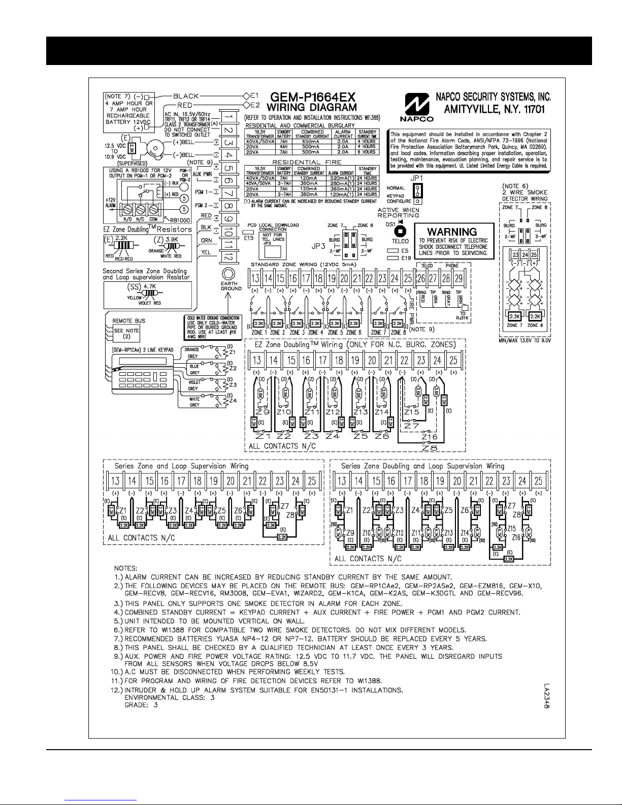
Page 64
GEM-P1664EX WIRING DIAGRAM
WI1387 7/05
GEM-P1664EX Programming Instructions
X
L
NAPCO Security Systems
 Loading...