


FCC Required Exhibit 12
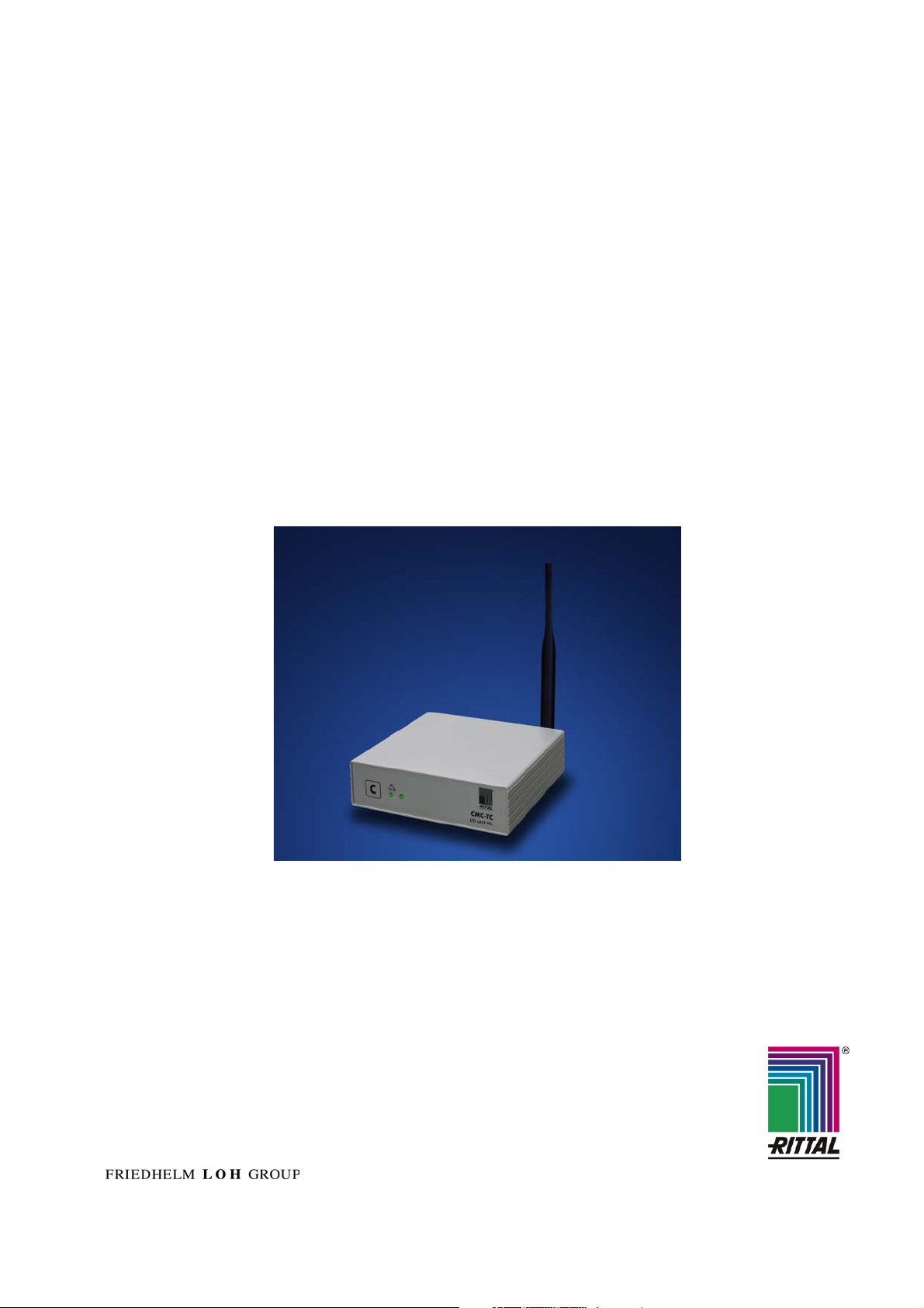
CMC-TC Wireless I/O-Unit
DK 7320.240
User Manual (UserMan)
Version 1.01
NA-08-0000-0025-1.01
Document Information
CMC-TC Wireless I/O-Unit (UserMan)
Document Information
Document Title: CMC-TC Wireless I/O-Unit (UserMan)
Document Version: 1.01
Published (yyyy-mm-dd): 2008-04-17
Current Printing: 2008-4-17, 1:39 pm
Document ID: NA-08-0000-0025-1.01
Document Status: Released
Disclaimer
Nanotron Technologies GmbH believes the information contained herein is correct and accurate at the time of release. Nanotron
Technologies GmbH reserves the right to make changes without further notice to the product to improve reliability, function or
design. Nanotron Technologies GmbH does not assume any liability or responsibility arising out of this product, as well as any
application or circuits described herein, neither does it convey any license under its patent rights.
As far as possible, significant changes to product specifications and functionality will be provided in product specific Errata
sheets, or in new versions of this document. Customers are encouraged to check the Nanotron website for the most recent
updates on products.
Trademarks
©
nanoNET
names are the sole property of their respective owners.
This document and the information contained herein is the subject of copyright and intellectual property rights under international
convention. All rights reserved. No part of this document may be reproduced, stored in a retrieval system, or transmitted in any
form by any means, electronic, mechanical or optical, in whole or in part, without the prior written permission of Nanotron
Technologies GmbH.
Copyright © 2008 Nanotron Technologies GmbH.
is a registered trademark of Nanotron Technologies GmbH. All other trademarks, registered trademarks, and product
Life Support Policy
These products are not designed for use in life support appliances, devices, or systems where malfunction of these products can reasonably be expected to result in personal injury.
Nanotron Technologies GmbH customers using or selling
these products for use in such applications do so at their own
risk and agree to fully indemnify Nanotron Technologies
GmbH for any damages resulting from such improper use or
sale.
Electromagnetic Interference / Compatibility
Nearly every electronic device is susceptible to electromagnetic interference (EMI) if inadequately shielded, designed, or
otherwise configured for electromagnetic compatibility.
To avoid electromagnetic interference and/or compatibility
conflicts, do not use this device in any facility where posted
FCC User Information
Statement according to FCC part 15.19:
This device complies with Part 15 of the FCC Rules. Operation is subject to the following two conditions: (1) this device
may not cause harmful interference, and (2) this device must
accept any interference received, including interference that
may cause undesired operation.
Statement according to FCC part 15.21:
Modifications not expressly approved by this company could
void the user's authority to operate the equipment.
RF exposure mobil:
The internal / external antennas used for this mobile transmitter must provide a separation distance of at least 20 cm from
all persons and must not be co-located or operating in conjunction with any other antenna or transmitter."
Statement according to FCC part 15.105:
This equipment has been tested and found to comply with the
limits for a Class A and Class B digital device, pursuant to Part
15 of the FCC Rules. These limits are designed to provide
notices instruct you to do so. In aircraft, use of any radio frequency devices must be in accordance with applicable regulations. Hospitals or health care facilities may be using
equipment that is sensitive to external RF energy.
With medical devices, maintain a minimum separation of 15
cm (6 inches) between pacemakers and wireless devices and
some wireless radios may interfere with some hearing aids. If
other personal medical devices are being used in the vicinity
of wireless devices, ensure that the device has been adequately shielded from RF energy. In a domestic environment
this product may cause radio interference in which case the
user may be required to take adequate measures.
CAUTION! Electrostatic Sensitive Device. Precaution should be used when handling the
device in order to prevent permanent damage.
reasonable protection against harmful interference in a residential installation and against harmful interference when the
equipment is operated in a commercial environment.
This equipment generates, uses, and can radiate radio frequency energy and, if not installed and used in accordance
with the instructions as provided in the user manual, may
cause harmful interference to radio communications. However, there is no guarantee that interference will not occur in a
particular installation. Operation of this equipment in a residential area is likely to cause harmful interference in which
case the user will be required to correct the interference at his
or her own expense.
If this equipment does cause harmful interference to radio or
television reception, which can be determined by turning the
equipment off and on, the user is encouraged to try to correct
the interference by one or more of the following measures:
• Reorient or relocate the receiving antenna.
• Increase the separation between the equipment and
receiver.
• Connect the equipment into an outlet on a circuit different
from that to connected.
• Consult the dealer or an experienced technician for help.
Page ii NA-08-0000-0025-1.01 © 2008 Nanotron Technologies GmbH.
EN CMC-TC Wireless I/O-Unit
DK 7320.240
Assembly, Installation and Operation
A38148 09 IT 74

US Representative
Rittal Corporation
One Rittal Place
Springfield, OH 45504
Telefon: +1(937)399 05 00
Fax: +1(937)390 55 99
eMail: rittal@rittal-corp.com
Website: www.rittal-corp.com
Published: 17/04/2008
Microsoft Windows is a registered trademark of Microsoft Corporation.
Acrobat Reader is a registered trademark of Adobe Systems Incorporated.

Table of Contents 1
1 Table of Contents
1 Table of Contents ..............................3
2 Documentation Notes .......................4
2.1 Associated Documents ....................... 4
2.2 Retention of the Documents ............... 4
2.3 Used Symbols ..................................... 4
3 Safety Notes....................................... 4
4 Unit Description.................................5
4.1 Housing ............................................... 5
4.2 Power Supply ...................................... 5
4.3 Connectable Sensors.......................... 5
4.4 Scope of supply................................... 5
4.5 Accessories......................................... 6
4.5.1 Required Accessories ......................... 6
4.5.2 Optional Accessories ..........................6
4.6 Proper Use .......................................... 6
5 Assembly ...........................................7
5.1 Assembly Notes .................................. 7
5.2 Assembling CMC-TC .......................... 7
9 Wireless I/O-Unit as Repeater ........ 17
9.1 Power Supply.................................... 17
9.2 Configuring a Wireless I/O-Unit as
Repeater ........................................... 17
9.3 Repeater Information Page .............. 17
10 Connecting an External Antenna... 18
11 Maintenance and Cleaning............. 18
11.1 18
11.2 Cleaning............................................ 19
12 Storage and Disposal ..................... 19
12.1 Storage ............................................. 19
12.2 Disposal ............................................ 19
13 Customer Service............................ 19
14 Technical Specifications ................ 19
15 Technical Glossary ......................... 20
16 Declarations of Conformity ............ 20
EN
6 Installation..........................................8
6.1 Safety and Other Notes ...................... 8
6.2 Connecting the voltage supply............ 8
6.3 Antenna adjustment ............................ 8
7 Commissioning..................................8
7.1 CMC-TC Wireless I/O-Unit
Commissioning.................................... 8
7.2 Registering Sensors............................ 9
7.3 Removing Sensors............................ 10
7.4 Closing Programming Mode ............. 11
7.5 Tips and Notes for the Sensor
Placement ......................................... 11
7.5.1 Tips for the Calibration of the Sensor
Locations........................................... 11
7.5.2 Introduction to the Wireless Data
Transmission for the Rittal Wireless
Sensor Network................................. 12
7.5.3 Wireless System Range Estimate..... 13
7.5.4 Troubleshooting ................................ 14
8 Operation .........................................15
8.1 Access Using a Browser ................... 15
8.1.1 Login Using a Browser...................... 15
8.1.2 Main Page View ................................ 15
8.1.3 General Overview (Status Window).. 15
8.1.4 Sensor Overview............................... 15
8.1.5 Sensor Configuration ........................16
8.1.6 Sensor Information............................ 16

2 Documentation Notes
EN
2 Documentation Notes
The audience for this guide is the technical specialists familiar with the assembly, installation and operation of the CMC-TC Wireless I/O-Unit.
• You should read this operating guide prior to the
commissioning and store the guide so it is readily
accessible for subsequent use.
Rittal cannot accept any liability for damage and
operational malfunctions that result from the nonobservance of this guide.
2.1 Associated Documents
The guides for other CMC-TC components and their
safety notes also apply together with this guide.
This guide can also be downloaded from
www.rimatrix5.com in the Internet and is also present as file on the CD-ROM of the Processing Unit
II:
German: 7320240VXXd.pdf
English: 7320240VXXe.pdf
To view the guide you require the Acrobat Reader
program; Acrobat Reader can be downloaded from
www.adobe.com
2.2 Retention of the Documents
This guide and all associated documents are part of
the product. They must be given to the operator of
the unit and must be stored so they are available
when needed.
2.3 Used Symbols
The following safety and other notes are used in this
guide:
Symbol for a handling instruction:
• This bullet point indicates that you should perform
an action.
Safety and other notes:
Danger!
Immediate danger to health and life!
Warning!
Possible danger for the product and
the environment!
3 Safety Notes
Observe the subsequent general safety notes for
the installation and operation of the unit:
− Assembly and installation of the CMC-TC Wireless I/O-Unit, in particular for wiring the enclosures with mains power, may be performed only
by a trained electrician. Other tasks associated
with the CMC-TC Wireless I/O-Unit, such as the
assembly and installation of system components
with tested standard connectors, and the operation and configuration of the CMC-TC Wireless
I/O-Unit may be performed only by instructed
personnel.
− Observe the valid regulations for the electrical
installation for the country in which the unit is installed and operated, and the national regulations
for accident prevention. Also observe any company-internal regulations (work, operating and
safety regulations).
− Prior to working at the CMC-TC system, it must
be disconnected from the power supply and protected against being switched on again.
− Use only genuine or recommended parts and
accessories (see Section 4.5 Accessories). The
use of other parts can void the liability for any resulting consequences.
− Do not make any changes to the CMC-TC Wireless I/O-Unit that are not described in this guide
or in the associated guides.
− The operational safety of the unit is guaranteed
only for its approved use. The limit values stated
in the technical specifications (see Section 14
Technical Specifications) may not be exceeded
under any circumstances. In particular, this applies to the permitted ambient temperature range
and to the permitted IP protection category. When
used with a higher required IP protection category, the Rittal CMC-TC must be installed in a
housing or enclosure with a higher IP protection
category.
− The operation of the CMC-TC system in direct
contact with water, aggressive materials or inflammable gases and vapours is prohibited.
− In addition to these general safety notes, also
observe any special safety notes listed for the
specific tasks in the individual sections.
Note!
Useful information and special features.
Unit Description 4
4 Unit Description
The Computer Multi Control Top Concept Wireless
I/O-Unit is an "intelligent" enclosure monitoring system installed in its own housing mounted on the
enclosure. The enclosure monitoring system uses
the various connected sensors to perform the complete physical monitoring of the enclosure, namely,
temperature, humidity, access control and digital
input module. All this information is transferred using
SNMP to a management station where it can be
administered. The CMC-TC Wireless I/O-Unit can
also be used as a repeater. The direct connection of
the CMC-TC power pack starts this function.
4.1 Housing
The CMC-TC Wireless I/O-Unit is contained in its
own housing that can be fastened with the supplied
Velcro strips to the inner side of the side wall, to the
punched sections with mounting flanges or to the
shelf of the enclosure. Mounting units (see Section
4.5.1 "Required Accessories") can also be used to
install the housing.
2
1
3
2 3
1
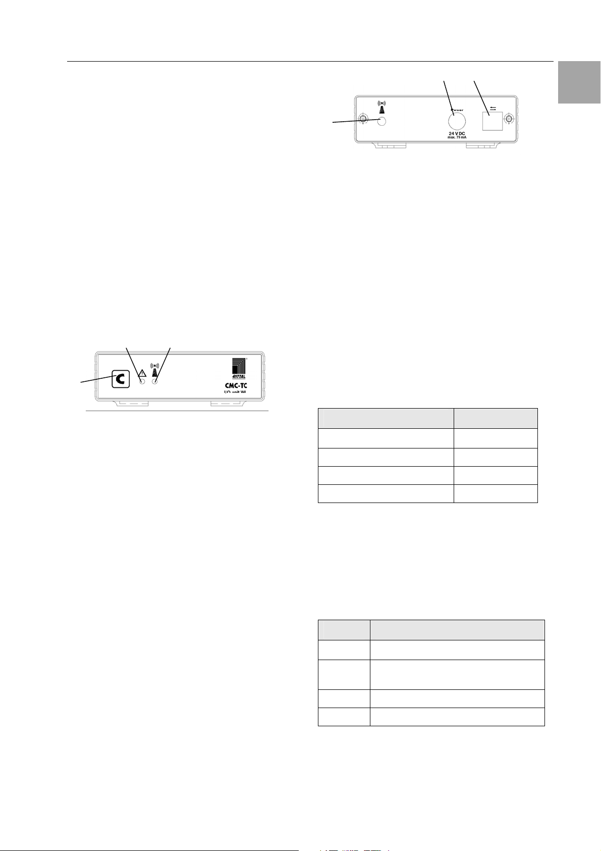
Fig. 2 CMC-TC Wireless I/O-Unit rear side
Key
1 Antenna connection
2 Power supply (optional)
3 Interface to Processing Unit II
4.2 Power Supply
The CMC-TC Wireless I/O-Unit is supplied with
power from the connected Processing Unit II. The
connection is established using an RJ45 cable. A
selection of various RJ45 cables is described in
Section 4.5 "Accessories".
All connected sensors have their own battery integrated in each sensor.
If you connect the CMC-TC Wireless I/O-Unit directly to a CMC-TC power unit, it operates as a
repeater.
EN
Fig. 1 CMC-TC Wireless I/O-Unit front side
Key
1 Acknowledge key (C key)
2 Status LED
- Off No operating voltage is present or
repeater mode
- Green OK sensor status
- Orange Warning sensor status
- Red Alarm sensor status
- Flashing green/orange/red
Configuration change
- Flashing red System is in reset
3 Wireless connection LED
- Off No operating voltage is present
- Green Normal operation
- Green interrupted briefly for some time [ms] ->
a data package is being sent
- Orange System is in repeater mode
- Red System in repeater mode has lost the
base station
- Flashing red System is in reset
- Flashing green/orange/red
System is in the log-in mode
4.3 Connectable Sensors
Sensor Model No.
Temperature sensor
DK 7320.505
Humidity sensor DK 7320.515
Access sensor DK 7320.535
Digital input module DK 7320.585
Tab. 1 Connectable Sensors
4.4 Scope of supply
The unit will be delivered in a packaging unit in fullyassembled state.
• Check the delivered components for completeness.
• Check that the packaging does not show any
signs of damage.
Quantity Designation
1
2 Self-adhesive Velcro fasteners
1 Antenna
1 Operating instructions
Wireless I/O-Unit
90 x 15 mm
Tab. 2 Scope of supply
4 Unit Description
EN
4.5 Accessories
4.5.1 Required Accessories
Depending on the country-specific specifications,
you require an appropriate connection cable for the
power pack of the CMC-TC PU II.
Accessories
Power
supply
for operation
as a
repeater
Connection
cable for
power
pack
Assembly
Connection
cable
Designation
Installation
power pack 24 V
IEC
100-230 V AC,
UL approval, 3 A
SELV
Installation
power pack 24 V
IEC
48 V DC
Connection
cable IEC connector
Country version
D
Connection
cable IEC connector
Country version
GB
Connection
cable IEC connector
Country version
F/B
Connection
cable IEC connector
Country version
CH
Connection
cable IEC connector
Country version
USA/CDN,
UL approval
FT1/VW1
Extension cable
IEC connector
and socket
1 U mounting
unit
1 U single mounting unit with
strain relief
RJ45; 0.5 m 7320.470
RJ45; 2.0 m 7320.472
RJ45; 5.0 m
P.ofRe-
quired
1 7320.425
Yes,
depending on
power
supply
1
1 7200.210
1
1
Yes,
once for
power
1
pack
1
1
1
Optional
1
11
Model
No.
7320.435
7200.211
7200.210
7200.213
7200.214
7200.215
7320.440
7320.450
7320.475
4.5.2 Optional Accessories
Accessories
External antenna
Wireless measuring unit
Tab. 4 Optional accessories
Max. required
number of
items
1 DK 7320.421
1 DK 7320.242
Model No.
4.6 Proper Use
The Rittal CMC-TC Wireless I/O-Unit serves as an
enclosure monitoring system for the monitoring and
administration of various enclosure parameters.
A use different from that described here is considered to be an improper use. Rittal cannot accept any
liability for damage resulting from the improper use
or the non-observance of this guide. The guides for
the used accessories may apply.
Tab. 3 Required accessories

5 Assembly
5.1 Assembly Notes
Install the CMC-TC Wireless I/O-Unit in an enclosure or in a suitable housing system so that it also
has additional protection from external effects. Also
consider the permitted ambient temperature and
humidity operational areas and the applicationrelated required IP degree of protection (see Chapter 14 Technical Specifications).
Note!
If you want to use the unit in
reapeater mode please register the repeater unit at the
I/O-Unit before installation. In
registration mode the range is
limited to 5m.
5.2 Assembling CMC-TC
Assembly 5
EN
Fig. 4 Assembly with Velcro fasteners
• Take the self-adhesive Velcro fasteners from the
supplied accessories and remove the protective
foil from the Velcro fasteners.
• Ensure that the adhesion surfaces are free from
grease and dust.
• Attach the Velcro fasteners to the housing of the
CMC-TC Wireless I/O-Unit and position the CMCTC Wireless I/O-Unit at the required attachment
location.
Fig. 3 Assembly with the mounting module
• Move the CMC-TC Wireless I/O-Unit on the retaining plate of the mounting module. Ensure that
the retaining plate sits between the guide rails of
the CMC-TC Wireless I/O-Unit.
2,4
3
1,5
Fig. 5 Assembly with 1 U mounting unit
1. Remove the two upper screws of the trim piece.
2. Remove the trim piece.
3. Move the CMC-TC Wireless I/O-Unit on the
retaining plate of the mounting unit. Ensure that
the retaining plate sits between the guide rails of
the CMC-TC Wireless I/O-Unit.
4. Replace the trim piece on the mounting unit.
5. Screw the trim piece back on the 1 U mounting
unit.

6 Installation
EN
6 Installation
Danger!
The assembly and installation may be
performed only by trained specialists.
6.1 Safety and Other Notes
− The Rittal CMC-TC system may be operated only
with connected protective earth conductor. The
protective earth conductor connection is made by
plugging in the IEC connection cable. This requires that the IEC connection cable at the power
supply side be connected with the protective
earth conductor.
− The electrical connection voltage and frequency
must conform to the rated values specified at the
rear of the housing and in the technical specifications (see page 19).
− Before commencing work on the Rittal CMC-TC
system, it must be disconnected from the mains
power supply and protected against being reconnected.
− Protect the connection cables using cable ties on
the used housing or enclosure.
− To prevent unnecessary cable losses, the used
cable lengths must not exceed the lengths specified in the technical specifications (see Chapter
14, page 19).
6.2 Connecting the Voltage Supply
1
Key
1 CMC-TC units connection
• Insert the other end of the RJ45 connection cable
in a free RJ45 socket with number 1 to 4 of the
CMC-TC Processing Unit.
After connection to the power supply, the Status
LED of the CMC-TC Wireless I/O-Unit flashes automatically. As soon as it is connected, the Status
LED illuminates alternately red, yellow and green.
6.3 Antenna Adjustment
The antenna of the I/O-Unit should always be adjusted parallel to the antennas of the sensors. If all
sensors are aligned vertical, the I/O-Unit antenna
must be also aligned vertical.
Warning!
FCC certification is valid only for the
2.4 GHz omnidirectional antenna
model IW-144 having a maximum 2 dBi
gain. An antenna having the same
specifications as model IW-144 but
with a gain of less than 2 dBi is an acceptable substitute.
7 Commissioning
7.1 CMC-TC Wireless I/O-Unit Commis-
sioning
Log in to the CMC-TC Processing Unit as described
in Section 8.1.1 Login Using a Browser.
Fig. 6 Connecting the voltage supply
Key
1 Power supply connection
You must connect the CMC-TC Wireless I/O-Unit to
the CMC-TC Processing Unit using the RJ45 connection cable mentioned in Section 4.5.1 "Required
Accessories".
• Insert the plug connector of the RJ45 connection
cable in the socket, as shown above, of the CMCTC Wireless I/O-Unit.
1
Power
12
43
Fig. 7 Connecting to the CMC-TC Processing Unit with
software version as of V. 2.46
P-I C
2
I0I0I
1
24 VDC
max. 2,5 A
1
Fig. 8 Commissioning
Key
1 Status LED
Once the CMC-TC Wireless I/O-Unit has been connected to the power supply, the Status LED of the
CMC-TC Wireless I/O-Unit flashes alternately with
the colours red, yellow and green.

Commissioning 7
1
Fig. 9 Unit detection browser window
Key
1 Status display of the sensor island
The "Unit detected" message appears in the
browser window of the Processing Unit.
Continue to press the C key on the Processing Unit
until the Status LED of the CMC-TC Wireless I/OUnit switches to a continuous green.
1
2
3
Fig. 10 Overview display browser window
Key
1 Overview display
2 Status of the I/O-Unit
3 Clear button
The CMC-TC Wireless I/O-Unit has now been detected.
1
Fig. 12 Wireless sensor (lower side)
Key
1 Status LED
2 Micro pushbutton
2
Press the Sensor micro-pushbutton (Push) located
on the lower side one second. The Status LED on
the sensor illuminates once briefly. If the registration
process was successful, the Wireless Connection
LED of the CMC-TC Wireless I/O-Unit flashes green
for approximately two seconds, then alternately red,
yellow, green. Simultaneously, the Status LED on
the CMC-TC Wireless I/O-Unit flashes alternately
red, yellow and green.
Note!
During the registration process, the distance between the sensor and the Wireless I/O-Unit may not exceed 5 m, because the I/O-Unit operates with reduced
transmission power in this mode.
No other I/O-Unit within a 5 m range must
be in registration mode during the registration process.
EN
7.2 Registering Sensors
1
Fig. 11 Wireless I/O-Unit (programming status)
Key
1 C key
2 Wireless connection LED
Press the C key on the Wireless I/O-Unit for three
seconds. The wireless connection LED now flashes
alternately red, yellow and green. The CMC-TC
Wireless I/O-Unit is now in programming mode.
2
Note!
For the commissioning of the sensors,
please observe information provided in
the Wireless Sensors manual.
1
2
Fig. 13 Sensor identification
Key
1 Status display of the sensor island
2 Clear button
"Configuration changed" appears in the browser
window. Press the Clear button (possibly several
times). The sensor is now registered to the I/O-Unit.
To test the registration, click in the overview display
the name of the I/O-Unit (here: CMC-TC-IOW). The
overview of the registered sensors is now displayed.

7 Commissioning
y
EN
Note!
A newly registered sensor receives the
sensor position with the smallest free
sensor position number.
Sensors have to be registered at the main I/O-Unit,
not at possibly used repeaters.
2
1
Fig. 14 Registered sensors overview
1 Sensor island / I/O-Unit
Click in the sensor overview on the name of the
sensor to be removed.
1
Fig. 16 Sensor Overview
Key
1 Sensor
Key
1 Registered sensors
2 Up button
Click the Up button to return to the overview display.
7.3 Removing Sensors
To remove a sensor from the I/O-Unit, first switch off
the sensor. To do this, press the key on the sensor
for at least five seconds until the Status LED flashes
very quickly.
To perform an immediate removal, switch off the
sensor as described above. On the configuration
page in your web browser, switch to the sensor
configuration.
To do this, click first in the main overview on the
sensor island / I/O-Unit to which the sensor to be
removed is connected (Fig. 15). You must be logged
in as administrator to use this function.
You now see the sensor configuration page.
1
Fig. 17 Sensor configuration
Key
1 Info button
Click the Info button to reach the sensor information
page.
1
Fig. 15 Main page overview
Ke

Commissioning 7
1
Fig. 18 Sensor Information
Key
1 Remove Sensor button
Click the Remove Sensor button to remove the sensor from the I/O-Unit.
Note
The communications timing between the
I/O-Unit and the sensor can require that
Remove Sensor must be clicked several
times before the remove command is accepted.
The sensor has now been removed and will no
longer be listed in the sensor overview. To reconnect the sensor, proceed as described in Section
7.2.
7.4 Closing Programming Mode
1
Fig. 19 Closing programming mode
Key
1 C key
2 Wireless connection LED
To close the programming mode, press the C key
on the CMC-TC Wireless I/O-Unit for two seconds.
The Wireless Connection LED will change to green.
If the programming mode is not closed manually, the
CMC-TC Wireless I/O-Unit returns automatically to
normal mode two minutes after the last registration
action.
2
7.5 Tips and Notes for the Sensor
Placement
To prevent malfunctions and to ensure reliable operation, the sensors should be positioned as described in Subsection 7.5.1. Detailed fundamental
information for the used wireless technology is described in Subsection 7.5.2.
Before starting the measurement, all I/O-Units and
repeaters must be installalled and all antennas must
be aligned.
7.5.1 Tips for the Calibration of the Sen-
sor Locations
To ensure the best possible reception of the individual sensors, the suitability of each sensor location
must be tested in advance using the wireless measuring system sensor (DK 7320.242).
Procedure:
i. Place the I/O-Unit into operation at the
planned location as described in Section
7.1.
Tip: Before starting the calibration, successively connect all sensors to the I/O-Unit.
This causes the sensors to be placed in
front of the measuring system sensor in the
registration list of the Processing Unit II.
This simplifies the subsequent administration.
ii. Connect the wireless measuring system
sensor to the I/O-Unit (see Section 7.2). To
do this, proceed as follows:
Place the I/O-Unit in programming mode
(press the C key for three seconds) > press
the key on the wireless sensor for five seconds (resets the sensor) > press the key on
the wireless sensor 1 second > the LED
flashes once briefly > sensor is registered >
leave programming mode of the I/O-Unit
(press the C key for two seconds, the wireless connection LED on the I/O-Unit lights
up green).
iii. Place the sensor attachment bracket at the
required sensor location (true for all sensor
types). The sensor front side edge must
point later in the I/O-Unit direction.
iv. Place the measuring system sensor on the
attachment bracket. The sensor position
during the measurement must be the same
as the operation position.
v. Perform a one-minute measurement with
the measuring system sensor: Press the
key on the measuring system sensor >
the result of the previous measurement will
be displayed for five seconds > "1" flashes
in the display (indicates the one-minute
measurement) > if a different number is displayed flashing, press the key several times
until the "1" appears > the measurement
EN

7 Commissioning
EN
starts after 5 seconds > the measurement
result (0-9) will be displayed after one minute.
(Details for the measurement and measuring times are contained in the operating instructions of the wireless sensors.)
vi. Measurement result 8-9: The connection is
suitable for the productive operation. Remove the measuring system sensor and
place the required sensor (temperature,
humidity, access or digital input) on the attachment bracket.
vii. Measurement result 0-7: Sensor location
not suitable. Change the position of the
sensor, use a repeater (see Chapter 9) or
use an external antenna. Then repeat the
measurement.
viii. Repeat steps iii. to vii. for each additional
sensor.
The wireless sensors now have an adequate connection to the I/O-Unit. This completes the installation of the system.
If problems in the wireless area occur during the
installation of the system, Subsection 7.5.4 describes the appropriate troubleshooting for correcting the fault.
Signal weakening
Even without obstacles, the sent wireless signal is
subject to a natural attenuation. The electric and
magnetic field strengths reduce by the factor 1/r
This means for distances exceeding approximately
1 m, the signal strength reduces by the factor 4
when the distance is doubled. Consequently, at
10 m distance from the transmitter, only 1/100 of the
signal strength compared with that at 1 m distance
will be received.
Any object through which the wireless signal needs
to penetrate causes an absorption of the signal (optical model: the light will be weaker). Whereas lightweight partition walls and doors cause only small
signal attenuation, masonry walls and coated glass,
persons or animals cause more signal attenuation;
metal causes large signal attenuation. Metal grids
act like metal walls.
2
.
7.5.2 Introduction to the Wireless Data
Transmission for the Rittal Wireless Sensor Network
This section describes the principles of the associated wireless technology that can be useful for setting up the wireless installation.
The sensor system operates with a frequency of
2.4 GHz. This means an optical consideration is
helpful for an initial planning for suitable installation
locations and distances.
The wireless signal is considered as being a light
beam with a dispersion characteristic appropriate for
light.
If you follow this model, it becomes clear that a direct line-of-sight connection between the base and
the sensor is the most favourable installation variant. Walls, furnishings, etc., in the vicinity can, however, act as a "mirror" that reflects the signal like
light. In this case, not only the original signal, but
also reflected signals from various directions arrive
at the receiving point. It is possible that the sent
data are incorrectly combined in the receiver. This
effect is called multi-path reception and can cause
major impairment of the reception quality.
This means even a line-of-sight connection between
the transmitter and the receiver is no guarantee for
a good connection.
Fig. 20 Absorption of the wireless signal by various
materials
Subsection 7.5.3 provides a general estimate of
what ranges can be expected for certain installation
situations.

Commissioning 7
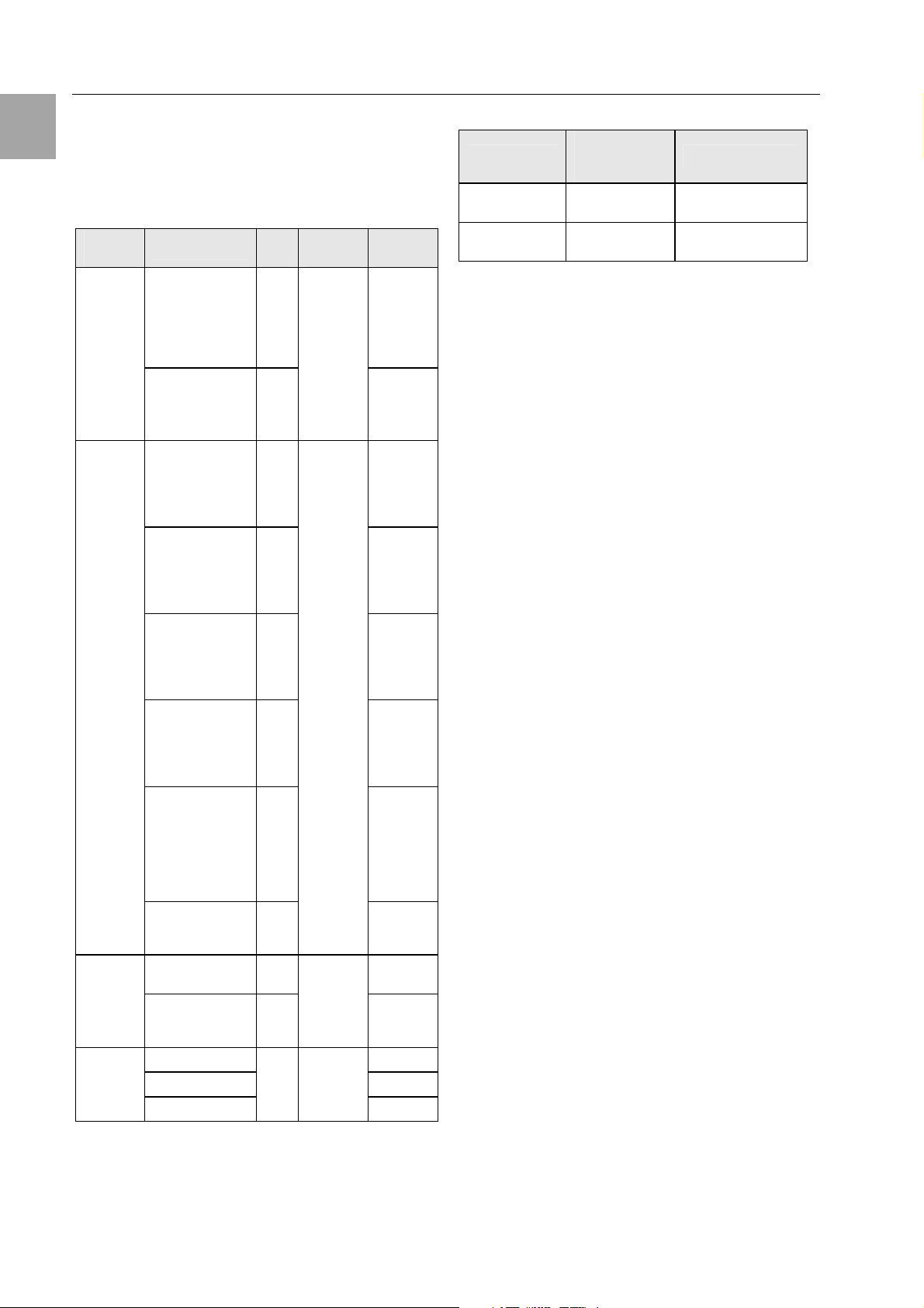
7.5.3 Wireless System Range Estimate
Scenario Sensor range
Single enclosure
Single enclosure (side)
Enclosure suite
Enclosure suite (side)
Table 5 provides an indication of the expected ranges for certain installation scenarios.
for steel door (closed) up to 20m
for steel door (70% vented) up to 35m
for glazed door up to 45m
for steel door (closed) up to 20m
for steel door (70% vented) up to 25m
for glazed door up to 25m
Note: These values are highly dependent on the
ambient reflection
for steel door (closed) up to 6m
for steel door (70% vented) up to 20m
for glazed door up to 30m
for steel door (closed) up to 6m
for steel door (70% vented) up to 10 m
for glazed door up to 10 m
Note: These values are highly dependent on the
ambient reflection
EN
Adjoining room (masonry: thickness 30 cm, concrete)
Corridor (line of sight, LOS)
Outdoor (line of sight, LOS)
for steel door (closed) up to 6m
for steel door (70% vented) up to 8m
for glazed door up to 10 m
up to 50 m
up to 200m
up to 50 m
Industrial building (line of sight, LOS)
Tab. 5 Wireless ranges

7 Commissioning
EN
Key
7.5.4 Troubleshooting
Fault Possible cause Testing and rectification
Sensor signal
is not
received.
Sensor does not send. Send a test packet by briefly pressing the key
on the sensor. LED must flash once.
If necessary, test the battery state using PUII.
Sensor lies outside the
range of the I/O-Unit.
Sensor has been removed or
interchanged.
Incorrect or no sensor registered
to the I/O-Unit.
Test the wireless link using the "wireless measuring system". If the display value is smaller
than "8", change the installation location. Alternatively, use a repeater or an external antenna.
Replace the sensor or/and re-register.
Check the sensor list on the Processing Unit
web page.
If necessary, re-register the sensor.
Sensor is
sometimes not
received.
Antenna not connected correctly. Check the antenna installation, plug connectors
and the laying of the antenna cable.
I/O-Unit is installed in a
shielded area.
Interfering transmitter (continuous transmitter) present.
Sensor lies in the fringe range
of the I/O-Unit.
Sensor lies in the fringe range
of the I/O-Unit.
Intermittent change of the
ambient conditions (enclosure,
door, objects, persons, interfering transmitter, etc.).
Test the wireless link using the "wireless measuring system". If the display value is smaller
than "8", use an external antenna.
Test the wireless link using the "wireless measuring system". Display value should be 8-9 in
the vicinity of the I/O-Unit. If necessary, rectify
the interfering transmitter.
Test the wireless link using the "wireless measuring system". If the display value is smaller
than "8", change the installation location or use
a repeater.
Increase the power reserves of the wireless link:
Mount the base and the sensor as high as possible to minimise the absorbing characteristics
of the floor, and the effect of objects and persons.
Increase the power reserves of the wireless link:
Change the installation location of the sensor or
the I/O-Unit (the other sensors of the I/O-Unit
then must be recalibrated) or use repeaters. If
necessary, rectify the interfering transmitter.
The installation location of the
sensor changes periodically
(mobile sensor).
Interfering transmitter
sometimes present.
Tab. 6 Troubleshooting
Change the installation location of the sensor so
that it lies in the receiving area.
Rectify or switch off the interfering transmitter.

Operation 8
8 Operation
The configuration of the individual sensors is described in the operating manual of the individual
wireless sensors.
8.1 Access Using a Browser
Open your Web browser as usual. Enter the IP
address of the Processing Unit in the address
field and start to build the page.
8.1.1 Login Using a Browser
1
2
3
Fig. 21 Login window
Key
1 User name
2 Password
3 Login or Clear button
Enter in the login window the http user name and
the http password of the Processing Unit. The use
has to have administration rights.
The factory setting of the CMC-TC Processing
Unit:
User name: admin
Password: admin
To confirm the input, click the Login button. To
clear the input, click the Clear button.
8.1.2 Main Page View
1
2
3 IP address of the Processing Unit
4 Link to the main page view
5 Setup link
6 Log link
7 Administration link
8 User name
9 User logout
8.1.3 General Overview (Status Window)
2 43 5
1
6
Fig. 23 I/O-Units overview
Key
1 Connection number and type of the I/O-Unit
2 Name of the I/O-Unit
3 Status display of the I/O-Unit
green: No warning/alarm
yellow: Warning
red flashing: Alarm / error (timeout)
red/yellow flashing: Configuration changed
4 Sensor overview link (see 8.1.4)
5 Sensor configuration link (see 8.1.5)
6 Clear – acknowledge events
Click the Clear button to acknowledge configuration changes of all connected sensors. This
causes the CMC-TC PU to be re-queried and the
Web page rebuilt.
EN
3
4
5
6
7
8
9
Fig. 22 Main page overview
Key
1 Address bar
2 Status window
8.1.4 Sensor Overview
2 3
1
4
Fig. 24 Sensor Overview

Key
4
1 List of all sensors connected to the Processing
Unit.
Clicking the sensor name displays the configuration page of the sensor
2 Link to the sensor configuration
(see 8.1.5)
3 Link to the status window (see 8.1.3)
4 Clear – acknowledge events
8.1.5 Sensor Configuration
You can individually set the attached sensors.
Because the structure of the configuration overview is generally always identical, it is shown here
as an example.
To reach this page, click the
the sensor name directly.
1
2
3
4
5
6
7
8
9
tool icon or click
8 Enter here the numbers 1 to 4 of the email adress
that should receive an email when an alarm is issued. To create the email adress, please consult
the operating manual of the CMC-TC Processing
Unit. The numbers must be entered separated by
an "&" character (e.g. 1&2&3&4).
9 Accepting the changes.
Info page for the specific wireless sensor.
(changes will not be accepted by clicking Info)
Reset all settings to the default values.
Note!
Further setting possibilities are described in the Wireless Sensor operating manual.
8.1.6 Sensor Information
1 2
3
Fig. 25 Configuring the sensor – overview
Key
1 Battery status
OK – battery OK
low – change battery
2 You can set for each sensor whether (enable) or
not (disable) the alarm relay is to be switched for
an alarm.
3 You can set for each sensor whether (enable) or
not (disable) the integrated alarm beeper is to be
activated for an alarm.
4 You can set for each sensor type whether after a
warning or alarm status the CMC-TC PU should
self-acknowledge (auto) or the administrator must
acknowledge manually (manual).
5 By clicking the individual option fields you can
determine to which of the entered trap-receivers
the traps for this sensor are to be sent.
6 By clicking the individual option fields you can set
which alarm configuration is to be enabled or disabled. You can specify the individual functions in
the "Setup – Timer" menu item and assign the
associated scheduler.
7 Enter here the numbers 1 to 4 of the mobile wire-
less numbers that should receive an SMS when
an alarm is issued. To create the mobile wireless
numbers, please consult the operating manual of
the CMC-TC Processing Unit. The numbers must
be entered separated by an "&" character (e.g.
1&2&3&4).
5
Fig. 26 Sensor information
Key
1 Name of the I/O-Unit to which the sensor is regis-
tered.
2 Tabs for additional sensors of the Processing
Unit.
3 Detailed information for the selected sensor
(here: Sensor 1)
Type: Sensor type
Sensor Status: Current measured value or status
of the sensor
Signal Quality: Signal quality of the Sensor –
I/O-Unit connection
Message Text: Message text for alarm messages
Serial Number: Serial number of the sensor
Software Version: Version number of the sensor
software
Transmit Packages: Data packages transmitted
from the sensor to the I/O-Unit
Measurement Cycle: Interval between two
measurements
Lifecheck Cycle: Interval between the
transmission of two Lifecheck packets. An Error
will be reported after 4 consecutive lifecheck signal losses.

Wireless I/O-Unit as Repeater 9
Hoplist: Information path of the sensor signal to
the Wireless I/O-Unit. The individual repeater stations through which the sensor signal passes on
the path to the I/O-Unit are listed here.
4 Button to remove the sensor from the I/O-Unit.
5 Values button returns to the sensor configuration
(see 8.1.5).
9 Wireless I/O-Unit as Re-
peater
The CMC-TC Wireless I/O-Unit can also be used
as a repeater for the Rittal CMC-TC wireless sensor network. This allows a long distance or a large
area to be covered using wireless sensors.
Note!
A maximum of nine CMC-TC Wireless
I/O-Units with repeater function can be
registered with a CMC-TC Wireless I/OUnit using the CMC-TC Processing
Unit.
9.1 Power Supply
1
Fig. 27 Power supply (repeater)
Key
1 Power supply connection
Use for the power supply a power unit described
in Subsection 4.5.1 Required Accessories. Ensure that a country-specific connection cable is
used.
now receive the "Configuration changed" message on the browser window. Click the Clear button two or three times until the message disappears. Click on the sensor overview pageon the
sensor name. The following window now appears.
1
2
3
4
5
6
7
Fig. 28 Repeater status
Key
1 Tab: The repeater will be registered with a free
port on the CMC-TC Wireless I/O-Unit (master).
2 Type: Sensor name (here: WL Repeater).
3 Sensor Status: The status of the CMC-TC Wire-
less I/O-Unit (repeater).
4 Battery Status: --.
5 Message Text: A name for the alarm message of
the CMC-TC Wireless I/O-Unit (repeater) is defined here.
6 Additional cofiguration: see sensor configuration
fig. 26.
7 Accept: Accept all changed settings.
Info: Call the information page of the CMC-TC
Wireless I/O-Unit (repeater) (see 9.3 Repeater
Information Page).
Reset: Reset all changed values.
Note!
During the sensor registration the distance between repeater an Wireless
I/O-Unit must not exceed 5m!
EN
9.2 Configuring a Wireless I/O-Unit
as Repeater
Once you have connected the Wireless I/O-Unit
to the power unit, it functions as a repeater. You
must now register the Repeater Wireless I/O-Unit
with the Wireless I/O-Unit using the CMC-TC
Processing Unit (master). If the repeater has already been registered at a different I/O-Unit, you
have to reset the repeater first. To reset, please
press c key for 10 seconds until the status LED is
flashing.
Press for two seconds the C key on the Wireless
I/O-Unit (master). The wireless connection LED
flashes red, yellow and green. You are now in
programming mode. Now go to the Repeater
Wireless I/O-Unit and press once the C key. You
9.3 Repeater Information Page
The information page shows all important parameters of the CMC-TC Wireless I/O-Unit (repeater).

1
1
2
3
4
5
6
7
8
9
10
11
Fig. 29 Repeater information page
Key
1 Type: The type of the registered unit or the sen-
sor.
2 Sensor Status: The current status of the unit
green: OK
red: Error
3 Signal Quality: The signal strength between the
CMC-TC Wireless I/O-Unit (repeater) and the
CMC-TC Wireless I/O-Unit on the Processing
Unit (master).
4 Message Text: The entered message text for
alarms.
5 Serial Number: The serial number of the CMC-
TC Wireless I/O-Unit (repeater).
6 Software Version: The software version of the
CMC-TC Wireless I/O-Unit (repeater).
7 Transmit Packages: The packages transferred to
the CMC-TC Wireless I/O-Unit (master).
8 Measurement Cycle: The measurement interval
(here every 10 seconds).
9 Lifecheck Cycle: The measurement interval for
querying the reachability to the CMC-TC Wireless I/O-Unit (master). An Error will be reported
after 4 consecutive lifecheck signal losses.
10 Hoplist: Information path of the sensor signal to
the Wireless I/O-Unit. The individual repeater
stations through which the sensor signal passes
on the path to the I/O-Unit are listed here.
11 Values: You can return to the CMC-TC Wireless
I/O-Unit (repeater) status page (see 9.2
Configuring a Wireless I/O-Unit as Repeater).
Hoplist example:
tab 3. You see the following message in the hoplist:
Fig. 31 Hoplist (repeater)
This means that the signals of the CMC-TC wireless humidity sensor on tab 2 using the CMC-TC
Wireless I/O-Unit (repeater) on tab 3 go to the
CMC-TC Wireless I/O-Unit (master).
To unregister the repeater from the I/O-Unit, you
have to reset the repeater. To reset, please press
C key for 10 seconds until the status LED is flashing.
10 Connecting an External An-
tenna
In difficult environments the external antenna can
be used to increase signal perfromance of the
CMC-TC Wireless I/O-Unit (see Subsection 4.5.2
Optional Accessories).
Fig. 32 Connecting an antenna
Key
1 Antenna connection
Unscrew the supplied antenna of the CMC-TC
Wireless I/O-Unit and screw on the antenna plug
of the external antenna.
The antenna of the I/O-Unit should always be
adjusted parallel to the antennas of the sensors. If
all sensors are aligned vertical, the I/O-Unit antenna must be also aligned vertical.
11 Maintenance and Cleaning
The Rittal CMC-TC Wireless Unit I/O-Unit is a
maintenance-free system. The housing does not
need to be opened for the installation or during
operation.
Note!
Opening the housing or any accessory
components will void any warranty and
liability claims.
11.1
Fig. 30 Hoplist example (repeater)
The humidity sensor was registered on tab 2. The
removed CMC-TC Wireless I/O-Unit (repeater) on

Storage and Disposal 12
11.2 Cleaning
Warning!
Danger of damage!
Do not use any aggressive substances, such as white spirit, acid,
etc., for cleaning because such substances can damage the unit.
Use a slightly moistened soft cloth to clean the
housing.
12 Storage and Disposal
12.1 Storage
If the device is not used for a longer period, we
recommend that it is disconnected from the mains
power supply and protected from dampness and
dust.
If the sensors are not used for a longer period,
they should be switched off.
Further information concerning the operating conditions is contained in the technical specifications.
12.2 Disposal
Because the CMC-TC Wireless Unit I/O-Unit consists primarily of the housing and PCB, the unit
must be disposed of through the electronic waste
recycling system when it is no longer required.
14 Technical Specifications
Designation CMC-TC
Housing
Housing type Plastic covering with metal trim
Height 1 U / 44.5 mm
Width 136 mm
Depth 129 mm
Weight without
packaging
Potential equalisation
Earthing -
Protection
category
Interfaces
Pushbuttons 1 membrane pushbutton, ac-
LED display 2 x (active/alarm, wireless con-
Input
Rated voltage /
rated current
approx. 0.6 kg
2)
-
2)
IP 40 to EN 60529
knowledge pushbutton
nection)
24 V DC, internal or
24 V for external power supply
120 mA
EN
13 Customer Service
If you have any technical questions or questions
concerning our product spectrum, contact the
following service address:
Tel.: +49 (0)2772/505-1855
http://www.rimatrix5.com
E-mail: info@rittal.de
Note!
To allow us to process your enquiry
quickly and correctly, please always
specify the article number in the subject
line for e-mails.
Further information and the current operating
manuals and updates of the Rittal CMC-TC can
be downloaded from:
http://www.rimatrix5.de/service_support/download
s.asp
Operational area
Temperature +5 to +45 °C
+42 to +113 °F
Storage temperature
Humidity 10% – 90% rel. humidity, non-
Technical Specifications
1)
Height units
2)
Not required because safety extra-low voltage
24 V DC
-20 to +60 °C
-4 to +140 °F
condensing

15 Technical Glossary
CMC-TC
CMC-TC (Computer Multi Control – Top Concept)
is a Rittal product used to monitor network enclosure components.
Internet browser
An Internet browser can be used to display html
pages (and pages that conform to a similar standard). In the case of CMC-TC PU II, they can be
configured using a user interface displayed with
an Internet browser.
Link
A link causes a jump to another Internet page or
establishes a connection between two Internet
pages.
SNMP (Simple Network Management Protocol)
The SNMP is a simple network management
protocol based on TCP/IP. It was developed to
monitor network components on a central management station.
Trap
Trap is the sending of SNMP messages.
Trap Receiver
The trap receiver is the receiver of SNMP messages.
16 Declarations of Conformity
This device satisfies the requirements of the following EU regulation:
1999/5/EU Regulation for wireless sys-
tems and telecommunications
terminals and the mutual recognition of their conformance
Hereby Rittal declares, that
CMC Wireless I/O-Unit and
CMC Wireless sensor is in
compliance with essential
requirements and other relevant provisions of Directive
1999/5/EC.
In France, the operation is only permitted indoors.
Certification
This device complies with Part 15 of the FCC
Rules. Operation is subject to the following two
conditions: (1) This device may not cause harmful
interference, and (2) this device must accept any
interference received, including interference that
may cause undesired operation.
The internal / external antennas used for this
mobile transmitter must provide a separation distance of at least 20 cm from all persons and must
not be co-located or operating in conjunction with
any other antenna or transmitter."
FCC ID: SIFCMCBASE0108V2
Statement according to FCC part 15.21:
Modifications not expressly approved by this
company could void the user's authority to operate the equipment.
Statement according to FCC part 15.105:
Note: This equipment has been tested and found
to comply with the limits for a Class A digital device, pursuant to part 15 of the FCC Rules. These
limits are designed to provide reasonable protection against harmful interference when the equipment is operated in a commercial environment.
This equipment generates, uses, and can radiate
radio frequency energy and, if not installed and
used in accordance with the instruction manual,
may cause harmful interference to radio communications. Operation of this equipment in a residential area is likely to cause harmful interference
in which case the user will be required to correct
the interference at his own expense.
Statement according to FCC part 15.105:
NOTE: This equipment has been tested and
found to comply with the limits for a Class B digital device, pursuant to Part 15 of the FCC Rules.
These limits are designed to provide reasonable
protection against harmful interference in a residential installation. This equipment generates,
uses and can radiate radio frequency energy and,
if not installed and used in accordance with the
instructions, may cause harmful interference to
radio communications. However, there is no guarantee that interference will not occur in a particular installation. If this equipment does cause
harmful interference to radio or television reception, which can be determined by turning the
equipment off and on, the user is encouraged to
try to correct the interference by one or more of
the following measures:
. Reorient or relocate the receiving antenna.
. Increase the separation between the equipment
and receiver.
. Connect the equipment into an outlet on a circuit
different from that to which the receiver is connected.
. Consult the dealer or an experienced radio/TV
technician for help.

Revision History
Ver si on Date Description/Changes
1.00 2008-04-15 Initial version.
Revision History
CMC-TC Wireless I/O-Unit (UserMan)
© 2008 Nanotron Technologies GmbH. NA-08-0000-0025-1.00 Page 21

About Nanotron Technologies GmbH
CMC-TC Wireless I/O-Unit (UserMan)
About Nanotron Technologies GmbH
Nanotron Technologies GmbH develops world-class wireless products for demanding applications based
on its patented Chirp transmission system - an innovation that guarantees high robustness, optimal use of
the available bandwidth, and low energy consumption. Since the beginning of 2005, Nanotron's Chirp technology has been a part of the IEEE 802.15.4a draft standard for wireless PANs which require extremely
robust communication and low power consumption.
ICs and RF modules include nanoNET TRX Transceiver, nanoLOC TRX Transceiver, and ready-to-use or
custom wireless solutions. These include, but are not limited to, industrial monitoring and control applications, medical applications (Active RFID), security applications, and Real Time Location Systems (RTLS).
nanoNET is certified in Europe, United States, and Japan and supplied to customers worldwide.
Headquartered in Berlin, Germany, Nanotron Technologies GmbH was founded in 1991 and is an active
member of IEEE and the ZigBee alliance.
Further Information
For more information about this product and other products from Nanotron Technologies, contact a sales
representative at the following address:
Nanotron Technologies GmbH
Alt-Moabit 60
10555 Berlin, Germany
Phone: +49 30 399 954 - 0
Fax: +49 30 399 954 - 188
Email: sales@nanotron.com
Internet: www.nanotron.com
Page 22 NA-08-0000-0025-1.00 © 2008 Nanotron Technologies GmbH.
 Loading...