


Please review this entire manual before
beginning assembly. Please visit our website
www.nanoplanes.net for more information.
This is not a toy. It is meant for use by the
experienced Radio Control Hobbyist
BUILDING INSTRUCTIONS
SHARK

INCLUDED ITEMS
YOU WILL NEED THE FOLLOWING ITEMS TO GET FLYING
of the
All Depron Parts with Graphics
Elevator and Aileron Push-rod wire
Three Micro Control Horns
All necessary wood parts
Carbon fiber wing spar and elevator spars
Fully illustrated building instructions
Little Screamers Brushless motor and 12 amp brushless speed controller
Four channel radio receiver and 2 micro/parkflyer servos
APC prop 6 x 5.5 and 3mm prop adapter
900 - 1320 mah 3 cell lipoly battery pack or similar - high discharge 12C +
Foam safe / odorless CA (UFO brand highly recommended)
Lightweight Spackling or hobby filler
Hinge tape or Scotch tape
Please note:
The graphics on this kit may vary in color and
design from the photos used in this manual

You will need to
detach the ailerons
and elevator from
both wing halves and
both elevator halves.
Flip over the elevator
on the table with the
graphic side face
down. With a hobby
knife carefully cut
down the hinge line to
cut the graphic tape.
If done correctly it
should be a clean cut.
Repeat this for the
other elevator as well.
The same process
needs to be done for
the ailerons. Place
one wing half face
down. You will need to
make two cuts.
The first cut shown
here.
The second cut
shown here.
Repeat this process
again for the remaining wing half.
Again if done correctly
and with a sharp
hobby knife you
should have a clean
cut as shown.
Find the following
parts and lay out on
your work table as
shown. This will
ensure you build a
right and a left side.
Glue the half fuselage
to the former as
shown. There will be
about 3mm edge at
the slot. This is the
way it should look.
Make sure it stays
straight with no warps
until glue sets. Stack
books on top to be
sure it stays true.
A closer view shows
the positioning as it
should be.
A closer view of the
positioning as it
should be in the aft
section of the fuselage half.
Complete both the left
and right fuselage
halves as shown.
You will need to widen
the slot for the elevator. Cut off about 3mm
from the top side.

The new slot should
be widened enough to
allow the 6mm elevator to slide in without
breaking the Depron.
Repeat this for the
other side. Make sure
you cut from the top
side. The side opposite the fuselage
doubler.
Glue the center piece
as shown. Make sure
it is laying completely
flat onto the edge of
the fuselage doubler.
Make sure you do not
cover up the wing
slots.
Glue the remaining
fuselage half to the
assembly. Stand on
end as shown to
ensure it is lined up
properly before
gluing.
Your fuselage assembly should be straight
with no warps or
bends or twists.
Take two of the wood
sticks and glue them
to the underside of
the fuselage as
shown. Sand a taper
to the tail end pieces
to make it fit.
Make sure both sticks
of wood are pressed
securely into the
corner for the full
length of the fuse
while gluing.
If you find that your
wings are curled then
you must straighten
them out using ruler
or hard flat tool.
Press with a sweeping action all the way
across the wing. Be
sure to hold the wing
firmly on both sides of
the spar line so that
you do not to break
the Depron. Pick up
the wing to see if it
still has a warp. If you
pressed too hard you
might find that the
warp has changed
directions. If this is the
case flip over the wing
and lightly sweep the
wing again to
straighten it out. After
a few swipes you
should find it easy
enough to make your
wing straight and true.
Try to make it as flat
as possible.
Although in this photo
this spar is wood,
your kit will include a
Carbon fiber spar.
Glue the wing halves
as shown and glue in
the wing spar as
shown.

Make sure you glue
the spar while the
assembly is on a flat
surface. Make sure
your wing stays
straight.
Sand a 45 degree
bevelled edge on the
ailerons. Make sure
you are sanding the
correct aileron and
you are sanding the
bottom side of it.
Apply Hinge tape or
Scotch tape to the
aileron top side first.
Trim the ends then
attach it to the wing.
Complete this for both
sides.
Then flip over the
ailerons all the way on
its back as shown.
Apply hinge tape to
the bottom as shown.
Trim the ends and
seal the aileron hinge
over the bottom side
of the wing.
Trim the end before
folding over the tape
to finish sealing the
aileron hinge.
Locate the 4 elevator
parts. Glue the to
halves together and
glue in the carbon
fiber spar. Work on
the elevator control
surfaces next.
Find the flat spar
about 13 inches and
the elevator section.
Place the spar over
the top of the elevator
as shown. Use it as a
guide to cut away the
color graphic tape.
Don’t discard the
tape. Peel it away
carefully as you will
re-apply it later.
Repeat the process
for both sides.
Remember save the
tape for reapplication.
Measure the flat spar
to length of the elevator spanwise. Cut the
length to match the
elevator span. Use
cutting shears. Be
careful of slivers and
splinters from the
carbon fiber.

Bend back the elevator all the way back
and tape the bottom
side to finish off this
hinge.
Your completed
elevator should have
3/8 inch travel freedom both up and
down.
Turn over your fuselage belly side up and
front pointing away
from you. Glue the
motor mount as
shown. This will give
you the proper right
thrust needed.
Cut various strips
from the scrap
Depron included in
the kit.
Using the scrap strips
fill in the gaps where
the motor mount has
been glued. Try to
make it a tight fit
wherever possible.
After filling the gaps
on both side use Thin
foam safe CA and
glue in the scraps.
This will help secure
the motor mount to
the fuse.
Glue the flat spar to
the front edge of the
elevator as shown.
Make sure it is flush
with the edge.
Glue the remaining
elevator half. Make
sure it is straight and
flush with the front
edge for the full span
of the elevator edge.
Re-apply the tape cut
off earlier over the
carbon fiber flat spar
as shown. Do both
sides.
Take this assembly
and place it on the
edge of the table on
its back, carbon fiber
and graphic side face
down. Sand a 45
degree bevel as
shown.
Use hinge tape or
Scotch tape on the
top first.
Attach the elevator
with the tape.

Continue with one
more level of filling
the sides with scrap
depron. Try to make it
from one piece on
each side. Secure
with more Thin foam
safe CA.
Sand the elevator slot
wider to accept the
elevator without
breaking the depron if
needed.
Glue the top part
together as shown.
Pinch it together with
your fingers without
cracking the depron.
Be gentle yet firm.
Squeeze the bottom
part as shown and
apply glue to fill any
poor glue adhesion.
The front of the
fuselage shown here
while belly side up.
The upright front view
of the fuselage.
With a sponge type
sanding block smooth
down the corners to
make a rounded
fuselage bottom.
Sand it round for the
full length of the
fuselage bottom.
This will help your
fuselage be more
streamlined and resist
drag better.
Fill any remaining
cracks and gaps with
lightweight spackling.
Let it dry and sand
smooth with fine sand
paper.
Use the end of an
Exacto knife and cold
crush all trailing
edges and leading
edges top & bottom
for all flying surfaces.
Wings, elevator and
rudder.
After cold crushing
the edges use a fine
sponge sand paper
and round smooth all
flying surfaces leading
and trailing edges.

Continue with this
process for all the
wings.
Just a reminder. It
makes it easier to
round the edges if
your first cold crush a
slight bevel to the
edges first.
It also helps to place
the wing on a flat
surface and sand with
a sponge sander to
bevel the edge first
then sand round
second.
Trial fit the elevator
and then make some
very light cuts to
remove the hinge
tape in order to allow
a better glue joint.
Carefully cut out
some hinge tape to
expose the Depron.
This will facilitate a
foam to foam glue
bond at this part of
the elevator.
Remove the cut out
tape. (Please note
that your kit will not
have wood as shown
in these pictures. Just
ignore this difference)
Attach the elevator
and make sure it is
squared up to the
fuselage. Once you
are sure it is aligned
then glue it with Thin
foam safe CA. Apply a
few drops and let it
seep into the joint.
Attach the rudder as
shown.
You will realize that
the bottom part of the
rudder does not reach
the fuselage.
It will look like this if
done correctly.
Do not glue this part
yet.
Cut out a couple of
scrap pieces sized to
fit into the tail openings and to create a
secure fitting for the
rudder.
Make sure your scrap
parts create a snug fit
into the open tail end
of the fuselage and
that it also creates a
secure grip of the
rudder.
Use more thin foam
safe CA to lock in the
rudder and then sand
a tapered effect as
shown.

Be careful not to
accidentally sand
other parts of the
plane.
Fill in the rest of the
fuselage end to make
a smooth airflow over
the fuselage. The
smooth shape of the
fuse helps reduce
drag greatly.
Use a ruler or hard
flat object to make
sure the main wing
slot is wide enough to
fit the wing. Press
while moving forward
and back along the
slot.
Make sure it is at
least 5 - 6mm thick for
a snug fit of the wing.
Use a file sander if
needed to widen this
slot.
After sliding in the
wing you might notice
that the fuselage may
have warped a bit.
Use a straight edge to
straighten it out.
It should be very easy
to line it up as shown.
Make sure the wing is
squared up properly
and glue it in place.
Again thin foam safe
CA works great.
Cut out a servo hole
to fit your servos. Do
not cut through the
wood as you will
weaken the fuselage
if you do. Just cut
away the Depron.
Measure the width of
your fuse and cut two
pieces of wood to
length. Attach your
servo first to the wood
as shown. Then glue
the wood to the fuse
with the servo
attached.
Make sure you line up
your servo to fit into
the hole you cut out.
This should bring your
servo arm just outside
the fuselage top.
Cut out the aileron
servo hole behind the
main spar line and
keep it centered as
well.
Again measure the
width of the fuselage
and cut to length the
two servo mounts.
Again attach the
mounts first to the
servo then insert and
glue into the fuselage
as shown.
Attach the push-rod to
the servo arm then
use the pushrod as a
guide for cutting a slot
down the side of the
fuselage.
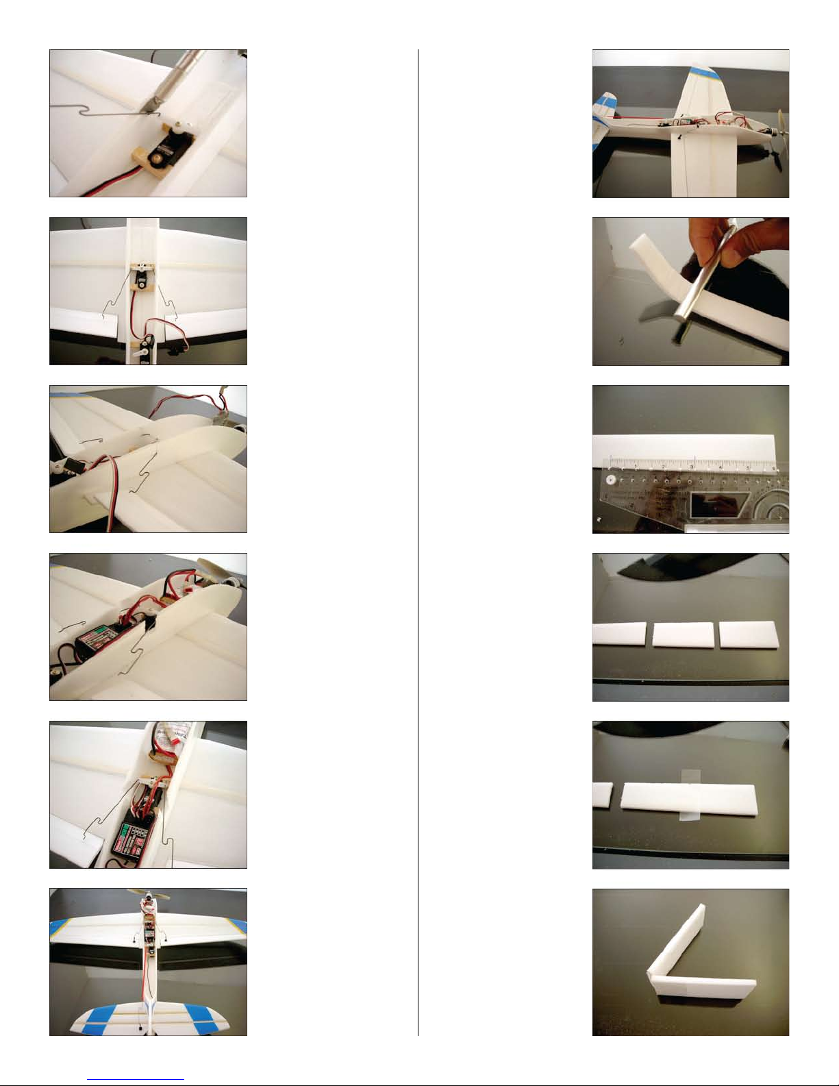
Cut down to the
height of the servo
arm as shown.
Repeat this for both
sides.
Make sure the future
positions of the
control horns are
evenly line up for both
sides.
Install your Rx behind
the aileron servo. Also
Cut out about 1/2 in.
to 3/4 in. to allow free
movement of the
aileron pushrods.
The Battery position is
in front of the aileron
servo. Install your
motor and ESC in
front of the battery.
Attach your control
horns on the ailerons
and elevator along
with the elevator
pushrod.
At this point your
should trial fit all your
gear and test if all
surfaces are moving
as they should and
check if the battery
position is right in
order to find the CG.
Which is about 1/4 in.
in front of the main
wing spar.
Cold crush the tail
end of the fuselage
cover and curve it
upwards as shown.
Measure and mark
from the front of the
cover piece at 3
inches and at 6
inches.
Cut off at the 3 and 6
inch points. You are
making a battery
hatch here.
Apply hinge tape to
the top side and trim
the edges.
Flip over and tape the
bottom. This is similar
to the aileron and
elevator hinges
except there is no
taper edge needed.
This hatch only needs
to move one direction.
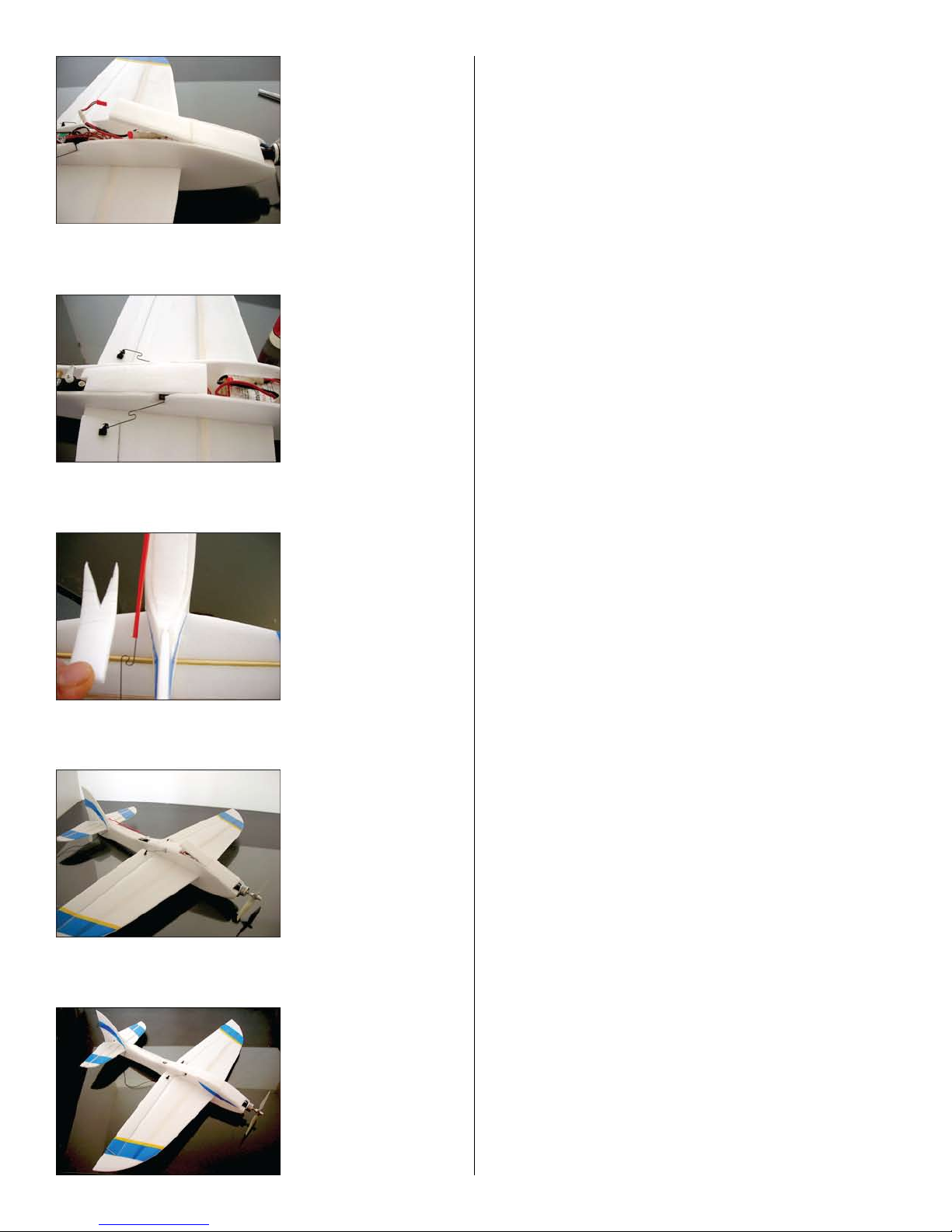
Glue the front part of
the hatch only. Cover
the hatch completely
with tape. The use
tape to secure the
hatch closed. Tape
over tape makes a
clean removable
surface for repeated
use of the hatch.
With the remaining
top cover pieces
measure and properly
cover the rest of the
fuselage. Cut out a
small part to leave
slightly exposed the
elevator servo only.
Slightly exposed.
Finish off the tail end
by cutting off the
unneeded part as
shown. Glue in place
the top cover. Tape
the pushrod tube to
the side of the fuselage.
Sand round edges for
the top portion of the
fuselage to complete
the smooth airflow
effect over the entire
aircraft. This will
greatly help reduce
drag to make a much
more enjoyable flying
experience.
This is the finished
aircraft.
The recommended surface throws are as follows:
Aileron up and down: 5/8 inch
Elevator up and down: 3/8 inch
CG: 1/8 in. - 1/4 in. in front of main wing spar
This aircraft can be extremely unmanageable with
higher throw settings than mentioned above. You
should try your first flights with less than recommended to get a feel of how this plane behaves
then change if desired. It is recommended that you
use a radio that has dual rates or exponential
settings so you can adjust these throw settings at
the field while testing it out to find your preferred
set up. Once you have it tuned in this can be a very
fun all around sport aerobatic aircraft with great
capacity for speed depending on the motor set up
used.
Thanks for choosing a Nanoplane. We hope you
enjoy your new NanoShark.
If you have any problems or questions we will be
more than happy to help you in any way we can to
make your experience as satisfying as possible.
Feel free to leave comments in the guestbook at
www.nanoplanes.net.
 Loading...