


WLAN-Minder User Manual
This page left intentional blank
Page 2 of 53 NGCD000423.005 NanoGlobes Ltd
WLAN-Minder User Manual
WLAN-Minder
User Manual
(c) COPYRIGHT 2003-2006 NanoGlobes Limited
• No Part of this manual may be reproduced without the
written permission of NanoGlobes Ltd.
• Software licences are granted for use with one processor
and are not transferable.
• NanoGlobes Ltd., make no representations or warranties
with respect to the contents hereof and specifically
disclaims any implied warranties of merchantability or
fitness for any particular purpose.
NanoGlobes Ltd NGCD000423.005 Page 3 of 53

WARRANTY
NanoGlobes Ltd warrant the WLAN-Minder RADIUS based control centre unit
against defective materials or workmanship for a period of one year from the date of
original purchase.
This warranty does not apply if the WLAN-Minder unit have been damaged by
neglect, improper handling or by any other cause not arising directly from defective
materials or workmanship.
WLAN-Minder User Manual
NOTICE
The information herein has been carefully checked and is believed to be entirely
accurate at time of going to press. However no responsibility is assumed for any
inaccuracies or typographical errors. Furthermore, no liability is assumed arising
from the use of any product detailed within. NanoGlobes Ltd, reserves the right to
make alterations without notice and recognises that the information contained within
does not convey to the purchaser any license under the patent rights of NanoGlobes
Ltd.
All trademarks acknowledged.
Page 4 of 53 NGCD000423.005 NanoGlobes Ltd

WLAN-Minder User Manual
Contents
1 Introduction .................................................... 7
1.1 About This Manual. ......................................... 7
1.2 WLAN-Minder Features...................................... 8
1.3 WLAN-Minder Front Panel Features ........................... 9
1.4 WLAN-Minder Back Panel Features ............................ 9
1.5 Using Smart Cards with the WLAN-Minder..................... 10
1.6 Using eTokens with the WLAN-Minder ........................ 10
2 Installing the WLAN-Minder. ...................................... 11
2.1 Configuring the IP Address. ................................. 11
2.2 Setting the BIOS Password. ................................. 14
2.3 Attaching The WLAN-Minder to the Network ................... 15
3 Initialising the WLAN-Minder - Creating the Root CA System. .......... 17
4 Configuring the WLAN-Minder..................................... 23
4.1 Logging in to the WLAN-Minder web interface. ................. 23
4.2 WLAN-Minder Welcome Menu ............................... 25
4.3 Configuring the Wireless LAN Access Point. ................... 26
4.4 Token Settings. ........................................... 28
4.5 Creating User Accounts. ................................... 29
4.6 Generating a Duplicate Administration Card.................... 31
5 Maintaining the WLAN-Minder. ................................... 33
5.1 Deleting User Accounts .................................... 33
5.2 Managing Users........................................... 34
5.3 Monitoring the Network. ................................... 36
5.4 Monitoring Logins. ........................................ 36
5.5 Viewing a User Token. ..................................... 37
5.6 Backing Up the WLAN-Minder Configuration Files. .............. 39
5.7 Restoring a WLAN-Minder Configuration. ..................... 41
5.8 Changing the System Time / Date............................. 43
6 Appendices.................................................... 44
6.1 Hardware Specification..................................... 44
6.2 Connector Pin-out. ........................................ 46
6.3 BIOS Administrator cable [NGL-210] pin-out. ................... 47
6.4 Windows Hyper-Terminal Setup for BIOS Administration. ........ 48
6.5 Unblocking a Blocked Smart Card / eToken. ................... 49
6.6 Two Character Country Codes. .............................. 50
7 References .................................................... 52
7.1 WLAN-Minder Workstation Client Users Manual. ............... 52
NanoGlobes Ltd NGCD000423.005 Page 5 of 53

WLAN-Minder User Manual
This page left intentionally blank.
Page 6 of 53 NGCD000423.005 NanoGlobes Ltd

1 Introduction
1.1 About This Manual.
This manual contains information pertinent to the configuration of a Wireless
LAN security system based on 802.1x authentication protocols. The security
system is based on using smart tokens in conjunction with WLAN-Minder client
software [Ref 1], and a central authentication service - provided by the WLANMinder.
The manual covers the installation of the WLAN-Minder, and the issuing of
security tokens such as smart cards and USB eTokens.
The WLAN-Minder solution is designed to operate with Wireless LAN
components that support the IEEE 802.1x Extensible Authentication Protocol.
Nearly all of the newer generation of Wireless LAN products (Client adapters
and Access Points) support this protocol. However certain low cost units and
earlier designs do not support the IEEE 802.1x protocol, these products cannot
be used in a WLAN-Minder solution. In general all components that have been
certified by the Wi-Fi Consortium as being WPA compliant should operate with
the WLAN-Minder.
WLAN-Minder User Manual
Only guidance is given in this manual about how the Access Points should be
configured. Each manufacturer will have their own menus and user interfaces
for configuration. Please refer to the Access Point User Manual for obtaining
information on setting up the Access Point unit.
NanoGlobes Ltd NGCD000423.005 Page 7 of 53

WLAN-Minder User Manual
1.2 WLAN-Minder Features
• Control of Wireless LAN users access to a wired network.
• Plug-and-play solution: no server software installation required.
• Support for IEEE 802.1x compliant EAP-TLS mutual authentication
protocol. Authenticating the client to the network, and the network to the
client.
• Automatic generation of PKI root certificate and user certificates.
• Simple Web based administrator’s interface.
• ISO7816S smart card reader-writer built-in for issuing smart cards
• USB interface built-in to support USB based eTokens.
• RS232 Port for attaching mini serial printer for issuing user PIN numbers.
(Option)
• Smart media socket for providing backup/restore of server configuration
settings.
Page 8 of 53 NGCD000423.005 NanoGlobes Ltd

WLAN-Minder User Manual
1.3 WLAN-Minder Front Panel Features
(1) Power On Indicator
(2) Access Point Network: Link and Traffic Status LEDs
(3) Local Network: Link and Traffic Status LEDs.
(4) eToken select LEDs used to indicate a USB eToken should be inserted.
(5) USB sockets for connecting eTokens to be initialised or read.
(6) Dual colour LEDs used to Indicate a smart card should be inserted or is
powered up.
(7) Smart card reader/writer slots.
1.4 WLAN-Minder Back Panel Features
(8) Power Socket +5VDC centre +.
(9) USB device interface for unit configuration from a host PC.
(10) RS232 Serial I/O interface for unit configuration [57600:8:N:1]
(11) Smart Media reader for configuration back up and restore.
(12) Reset button.
(13) Local Area Network Ethernet connector 10/100Mbps.
(14) Access Point Network Ethernet connector 10/100Mbps.
NanoGlobes Ltd NGCD000423.005 Page 9 of 53
WLAN-Minder User Manual
1.5 Using Smart Cards with the WLAN-Minder
Smart cards are used to store a user’s identity and his network configuration
information. The smart card is used to verify the identity of the owner by
checking the PIN number entered by the owner.
The WLAN-Minder supports two ISO-7816 compliant smart card readers. They
are labelled as [User] and [Admin] respectively. Beside each card slot is a bicolour LED, which is used to signal the following states when the web browser
interface is in use:
} A GREEN flashing LED by a card slot is a prompt for the user to enter a
smart card into that slot.
} A RED LED indicates a card is inserted and powered up. The user should
NOT remove the smart card when the RED LED is lit.
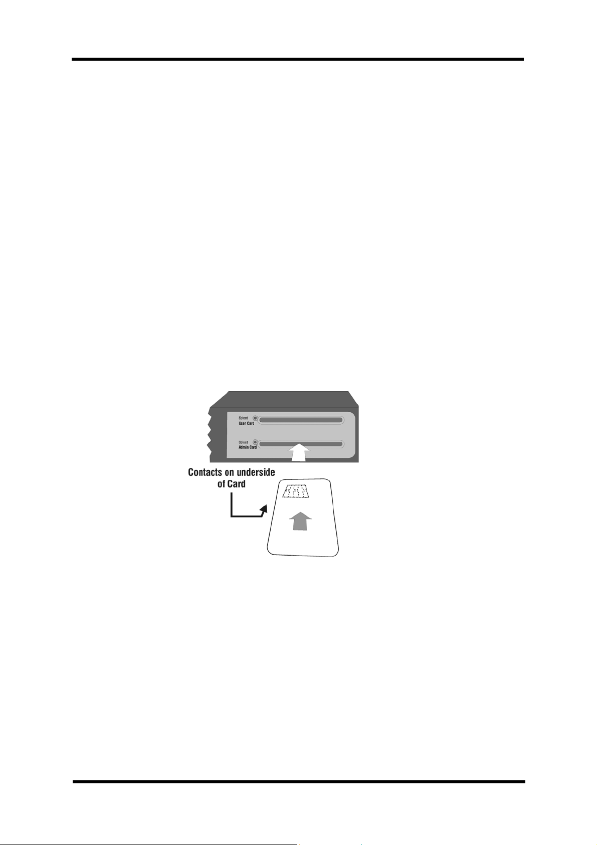
INSERTING THE SMART CARD
The contacts surface of the smart card should be face down, and the card
inserted with the contacts at the edge closest to the centre of the WLAN-Minder
unit.
1.6 Using eTokens with the WLAN-Minder
USB eTokens may be used as an alternative to a smart card for storing a user’s
identity and network configuration information.
The WLAN-Minder supports two USB interfaces capable of supporting an
eToken. They are labelled as [User] and [Admin] respectively. Beside each USB
socket is an GREEN LED.
} A GREEN flashing LED by a USB socket is a prompt for the user to enter
an eToken. The Flashing will stop when the eToken is inserted.
ENSURE the CORRECT ORIENTATION is used when INSERTING the
eToken.
Page 10 of 53 NGCD000423.005 NanoGlobes Ltd

WLAN-Minder User Manual
2 Installing the WLAN-Minder.
} The WLAN-Minder must first be given a valid IP network address before it
can be placed on the network. This is achieved by using the BIOS menu
as outlined in this section. Once the IP address has been configured all
further configuration is performed using a web browser interface.
} The BIOS menu must be used to set the IP address. This menu can only
be entered from the SERIAL RS232 port on the read panel of the WLANMinder.
2.1 Configuring the IP Address.
} Connect the WLAN-Minder Administrator RS232 port to a serial COM port
on a PC using the provided NGL-210 cable (9-D Female to 9-D Female).
} Connect one end of the supplied RS232 Cable to the connector labelled
[Administration RS232] on the rear panel of the WLAN-Minder.
} Connect the other end of the cable either to a Serial Terminal or to the
COM1 (or COM2) port of a PC running a terminal emulation program [See
Appendix 6.4]. The Terminal should be configured for:
[Baud: 57600, Data Bits: 8, Parity: None, Stop Bits: 1, Flow Control:
None]
} Plug in the supplied Power adapter into a Main’s power outlet, then
connect the power jack on the flying lead to the WLAN-Minder power
connector on the rear panel.
NanoGlobes Ltd NGCD000423.005 Page 11 of 53

WLAN-Minder User Manual
} The RED Power LED will light and the GREEN ADMIN CARD LED will
flash. The following prompt will appear on the terminal.
---------------------------------------------------------- BIOS v1.11.1 (c) 2005 NanoGlobes Ltd.
---------------------------------------------------------- If you want to skip the BIOS command mode, type enter or
wait a few seconds. After this, the system will boot
automatically.
BIOS(0)>
} NOTE: While logged in to the BIOS menu system the GREEN
ADMIN CARD LED will continue to flash.
} Enter the text: login<Enter>
} NOTE: The login command will only be accepted while the
GREEN smart card LED is flashing. (Approx. 5 seconds
from RESET/Power ON).
---------------------------------------------------------- BIOS v1.11.1 (c) 2005 NanoGlobes Ltd.
---------------------------------------------------------- If you want to skip the BIOS command mode, type enter or
wait a few seconds. After this, the system will boot
automatically.
BIOS(0)>login
Password: ********
BIOS(1)>
} At the password prompt: password<Enter>
} At the BIOS prompt enter the text: setup<Enter>
} The user will be prompted for the password. (Default is “password”)
} The BIOS will prompt for the IP Address, the IP Subnet Mask and the IP
Gateway address.
} The user should set the IP Address and IP Subnet mask to a suitable
value to be compatible with the network that the WLAN-Minder is to be
attached to.
} The unit then prompts for a TFTP Server path and file name, and the IP
Address of the TFTP server. These parameters may be ignored at this
time. Just use the <Enter> key to skip past these prompts.
Page 12 of 53 NGCD000423.005 NanoGlobes Ltd

WLAN-Minder User Manual
BIOS(1)>setup
Enter password : ********
LAN IP [192.168.1.100] ? 192.168.1.66
LAN MASK [255.255.255.0] ? 255.255.255.0
LAN GATEWAY [192.168.1.1] ? 192.168.1.200
TFTP Server IP [192.168.1.33] ?
TFTP Home Directory [/home/tftp] ?
Write System Configuration Parameters to Flash ...Done!
BIOS(2)>
} The settings are then automatically written to flash memory within the
WLAN-Minder.
} The user may view the settings to confirm the unit is configured correctly
by using the “ view” command.
BIOS(2)> view
Read System Configuration Parameters from flash ...Done!
+==================================================+
| System Configuration Table |
+==================================================+
| System Parameters |
| Vendor Name : NanoGlobes Ltd. |
| Host Name : NGLMinder_802328 |
+--------------------------------------------------+
| Upgrade Parameters |
| TFTP home : /home/tftp |
| TFTP Server : 192.168.1.33 |
+--------------------------------------------------+
| LAN Configuration Parameters |
| LAN MAC : 00:c0:bf:80:23:28 |
| WAN/AP MAC : 00:c0:bf:90:23:28 |
| LAN IP : 192.168.1.66 |
| LAN SUBNET : 255.255.255.0 |
| LAN Gateway : 192.168.1.200 |
+==================================================+
BIOS(3)>
} Once the IP settings have been set, it is STRONGLY RECOMMENDED
that the user change the BIOS Password to prevent unauthorised
changes to the IP settings. Of the WLAN-Minder.
} For the changes to take effect and to restart the unit, either cycle the
power to the unit (Power Off / On) or depress and release the RESET
switch which is accessible on the rear panel of the WLAN-Minder unit.
NanoGlobes Ltd NGCD000423.005 Page 13 of 53
WLAN-Minder User Manual
2.2 Setting the BIOS Password.
} The user should change the default BIOS password to protect the
configuration of the WLAN-Minder.
} To change the BIOS password the user must enter the BIOS menu in the
manner described in 2.1
} At the prompt enter the password command: passwd
} The user is prompted to enter the existing password. (The manufacturing
default password is “password”).
} Then the user is prompted to enter his new password twice. Note the
password letters are not echoed directly, only a “*” character is displayed
for each character typed.
} If the two password entries do not match each other a message “Input
Error - Password not changed.” is displayed. The user must run the
passwd command again.
---------------------------------------------------------- BIOS v1.11.1 (c) 2005 NanoGlobes Ltd.
---------------------------------------------------------- If you want to skip the BIOS command mode, type enter or
wait a few seconds. After this, the system will boot
automatically.
BIOS(0)> login
Password: ********
BIOS(1)> passwd
First enter the current password ...
Password: ********
New password (max 15 characters): ********
Confirm new password : ********
BIOS(2)>
Page 14 of 53 NGCD000423.005 NanoGlobes Ltd

WLAN-Minder User Manual
2.3 Attaching The WLAN-Minder to the Network
} The WLAN-Minder should only be attached to the user’s LAN once the IP
address has been configured as outlined in section 2.1,
} The WLAN-Minder should be connected by a CAT-5 Ethernet cable
directly to a 10/100MB Ethernet Hub or Switch.
} The connection must be made using the connector labelled [Network
LAN] on the rear panel of the WLAN-Minder unit.
} Check the LAN Link light on the front panel of the WLAN-Minder lights up
(GREEN).
} The user may confirm that the Ethernet link is working by issuing a PING
command to the WLAN-Minder from another computer on the same
subnet network.
Microsoft Windows 2000 [Version 5.00.2195]
(C) Copyright 1985-2000 Microsoft Corp.
C:\>ping 192.168.1.66 <---- Use IP address set in the WLAN-Minder
Pinging 192.168.1.66 with 32 bytes of data:
Reply from 192.168.1.66: bytes=32 time=10ms TTL=255
Reply from 192.168.1.66: bytes=32 time<10ms TTL=255
Reply from 192.168.1.66: bytes=32 time<10ms TTL=255
Reply from 192.168.1.66: bytes=32 time<10ms TTL=255
Ping statistics for 192.168.1.66:
Packets: Sent = 4, Received = 4, Lost = 0 (0% loss),
Approximate round trip times in milli-seconds:
Minimum = 0ms, Maximum = 10ms, Average = 2ms
NanoGlobes Ltd NGCD000423.005 Page 15 of 53

WLAN-Minder User Manual
} If the Ping fails to elicit a response from the WLAN-Minder, the user
should check:
} The Ethernet cable is plugged in the LAN Network connector on the
WLAN-Minder.
¤ The IP Address of the WLAN-Minder is set correctly.
¤ The IP Sub Net Mask of the WLAN-Minder is set correctly.
¤ The WLAN-Minder LAN LINK LED is lit GREEN.
¤ The WLAN-Minder DATA LED flashes YELLOW when data is
present on the network.
¤ The Computer issuing the PING is on the same Subnet as the
WLAN-Minder.
¤ The Computer issuing the PING is not behind a firewall.
} When successful communication has been established with the WLAN-
Minder, the remaining configuration can be completed from a web
browser such as Microsoft’s Internet Explorer, or Netscape Navigator etc.
} Simply start the web browser on a computer attached to the same subnet
network as the WLAN-Minder, and in the Location bar of the web browser
enter the IP address of the WLAN-Minder (e.g. http://192.168.1.66). The
WLAN-Minder menu system will then be displayed.
Page 16 of 53 NGCD000423.005 NanoGlobes Ltd

WLAN-Minder User Manual
3 Initialising the WLAN-Minder - Creating the Root CA
System.
A new WLAN-Minder must first be initialised with a Root CA certificate system1.
When the unit is first powered on it will automatically enter the correct mode for
the administrator to setup the Root CA system.
} Ensure the WLAN-Minder is attached to the LAN as described in section
2.3
} Start a web browser on a computer attached to the same subnet network
as the WLAN-Minder.
} In the Location bar of the web browser enter the IP address of the WLAN-
Minder.
} After a few seconds, the date and time screen will be displayed.
1
NanoGlobes Ltd NGCD000423.005 Page 17 of 53
Effectively the Root CA Certificate is a master certificate used to identify the
WLAN-Minder and it is used to electronically sign the User certificates
generated by the WLAN-Minder unit.

WLAN-Minder User Manual
} The user must enter the correct date and time. This is an important
operation as the date/time entered is used as a reference in checking the
validity of certificates. See Section 5.8. Each parameters is two numeric
digits.
} With the correct date and time entered click the Set Date and Time
button.
} The System Initialisation menu screen will then be displayed.
} When initialising the system for the first time or for generating a new
certificate system, the administrator should first insert the administrator
smart card and then complete the Admin Details section as follows:
Page 18 of 53 NGCD000423.005 NanoGlobes Ltd

WLAN-Minder User Manual
Admin Password: Up to 16 characters. In the range ‘a’..’z’, ‘A’..’Z’, ‘0'..’9',
“%&*+@~?#{}!”. Note the Alpha characters are case
sensitive - so ‘A’ is treaded as different character from ‘a’.
This password is used to provide the security for the backup
and restore facility of the WLAN-Minder.
Admin Password. (Confirm) Enter the Password a second time, in order to check
the correct value is stored by the system.
Admin Smart Card PIN The PIN number of the Administrator card. If this is a blank
card direct from the manufacturer the manufacturer will
indicate what the default PIN code is (Typically 0000). If the
card is a used card, then the Administrator must have
access to the PIN code either from their records or the
issuing department.
New Admin PIN If the Administrator wishes to change the current PIN, then
the new PIN to be used should be entered in this field. This
is optional - the Administrators does not have to change the
PIN.
New Admin PIN (Confirm) If the Administrator has chosen to change his PIN,
the new PIN must be entered a second time for
confirmation.
¤ With the Admin details entered the administrator should then move to the Root
CA Details section of the display and enter the following information:
Root CA Validity Period The Number of DAYS the newly created certificate
system on the WLAN-Minder is to be valid for. When
this value expires ALL users of the system will have
to have their certificates re-issued.
5 Years ~ 1825 Days
3 years ~ 1095 Days
2 Years ~ 730 Days
1 Year ~ 365 Days
NOTE: Each user certificate will have its own
validity period independent of this setting.
(Except a user validity period cannot exceed
the value set here.)
WARNING: Once a system has been
generated, its validity period cannot be
changed.
Root CA Company Unit: Alpha Numeric Eg: Accounts
NanoGlobes Ltd NGCD000423.005 Page 19 of 53

WLAN-Minder User Manual
Root CA Company Name: Alpha Numeric Eg: A B C
Industries
Town/City: Alpha Numeric Eg: Newbury
County/State: Alpha Numeric Eg: Berkshire
Country Code: See Section 6.6 Eg: GB
Root CA Common Name: Alpha Numeric Eg: ABCI_Root_CA_S
erver.
NOTE: No space characters should be
present in the Common Name
text.
Email Address: Standard format Eg:admin@abcind.com
¤ Once the Administrator has entered the above information and checked
that it is correct, the Generate New System button should be clicked.
¤ The Root CA generation process takes about 60 ~ 90 seconds to
complete. The Administrator is prompted to enter the Administrator’s
smart card if he hasn’t already done so.
¤ When the Rebooting message is displayed the user should click the Back
button.
¤ The system initialisation process is now completed. The Administrator will
now be able to login to the WLAN-Minder settings menu to configure the
unit and create users on the system.
Page 20 of 53 NGCD000423.005 NanoGlobes Ltd

WLAN-Minder User Manual
4 Configuring the WLAN-Minder.
Before a secure Wireless LAN environment can be implemented, the WLANMinder and the wireless Access Points must be configured.
¤ The WLAN-Minder must be initialised with the necessary information for it
to be able to communicate with the Access Point(s).
¤ The WLAN-Minder must be used to issue the smart cards or eTokens for
each user that is going to use the system.
4.1 Logging in to the WLAN-Minder web interface.
} In the Location bar of the Web browser enter the IP address of the
WLAN-Minder.
} After a few seconds a screen will be presented prompting the user to
enter the Administrator Smart Card (if it is not already inserted.)
} The user should then insert the smart card into the card slot labelled
“Admin Card”.
} Once the card is inserted the user should click “Continue”.
NanoGlobes Ltd NGCD000423.005 Page 21 of 53
WLAN-Minder User Manual
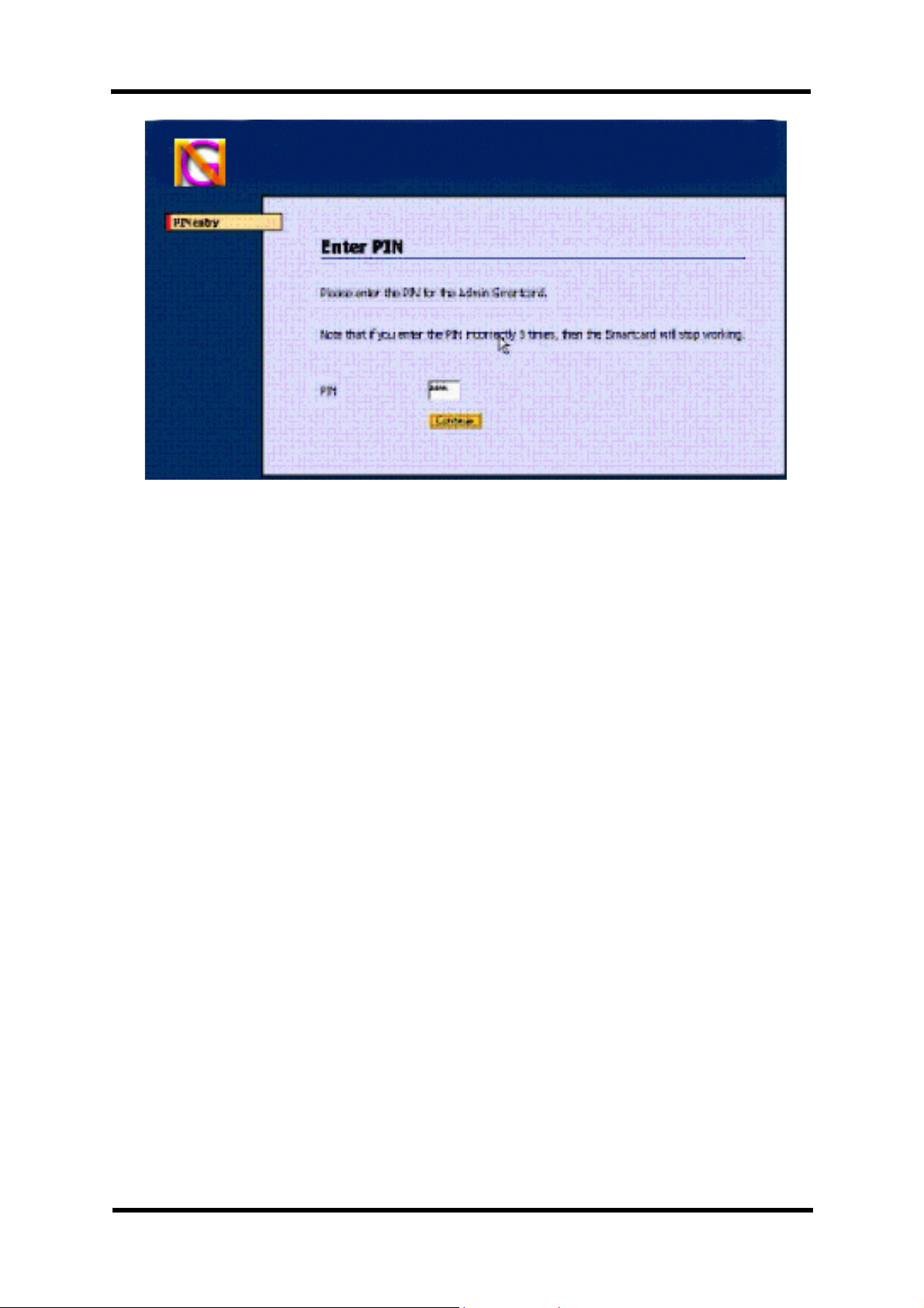
} The user will then be prompted to enter the PIN associated with the
Administrator card.
} If the correct PIN is entered, the user will see a welcome screen to the
administration features of the WLAN-Minder unit. See section 4.2
WARNING: Repeated attempts at entering the wrong PIN will result in the
Administrator card being blocked. Special tools will be
required to unblock the card.
} Start a web browser on a computer attached to the same subnet network
as the WLAN-Minder.
} In the Location bar of the web browser, enter the IP address of the
WLAN-Minder.
} The WLAN-Minder will display a screen requesting the user to insert his
identity administrator eToken or smart card (see section 10).
} Once the smart card or USB eToken has been detected by the WLAN-
Minder, the Administrator user will prompt to enter his PIN code.
} If the correct PIN code is entered the Administration Welcome Screen is
displayed.
WARNING Entering 3 (three) consecutive incorrect PIN codes will LOCK
OUT the smart card. The user will not be able to use that card
again until it is UNBLOCKED by an administrator.
Page 22 of 53 NGCD000423.005 NanoGlobes Ltd

WLAN-Minder User Manual
4.2 WLAN-Minder Welcome Menu
Once the Administrator is successfully logged in to the WLAN-Minder, the
welcome screen is presented.
This screen presents access to all the control functions supported by the WLANMinder.
When configuring the WLAN-Minder for the FIRST time, the Administrator
must perform the following actions in the order listed:
} Configure the parameters for the Access Points. [Access Point
Settings]
} Select default token type to be used by the system smart card / eToken
[Settings]. (This setting can be overridden each time a user is created on
the system.)
} Set up the initial User accounts. [Add User]
The other functions provided allow the administrator to view the status and
history of the connections made from the Wireless Network. In addition, existing
users can be removed from the data base or temporarily barred from the
network.
NanoGlobes Ltd NGCD000423.005 Page 23 of 53
WLAN-Minder User Manual
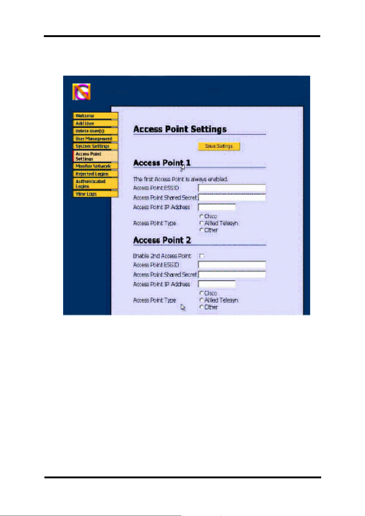
4.3 Configuring the Wireless LAN Access Point.
From the “Welcome” menu select the [Access Point Settings] option.
At least one valid access point must be defined, the first Access Point data
should be entered in the Access Point 1 form.
Additional Access Points may be configured, in the same manner as the first
Access Point by using the subsequent Access Point forms displayed on this
menu screen.
Note that each additional Access Point must be specifically enabled by clicking
on the Enable nth Access Point selection box.
Access Point ESSID: The user should enter the name or
string of characters used to identify the
Wireless Network. This must be the
same value as is set in the Access
Point.
Page 24 of 53 NGCD000423.005 NanoGlobes Ltd

WLAN-Minder User Manual
Access Point Shared Secret: This is a secret string of characters,
numbers or symbols that only the
Access Point and WLAN-Minder share
so that the WLAN-Minder can identify
the Access Point. This must be the
same value as is set in the Access
Point.
Access Point Type: The user should select the type of
Access Point being used. If the Access
Point name is not listed select other.
Access Point IP Address The IP Address of the Access Server (in
dotted decimal format: e.g.
192.168.1.120)
Access Point IP Mask: The IP Mask of the Access Server (in
dotted decimal format: e.g.
255.255.255.0)
Once all the Access Point parameters have been entered the [Save
Settings] button should be clicked causing the WLAN-Minder to save all
Access Point parameters.
NanoGlobes Ltd NGCD000423.005 Page 25 of 53

4.4 Token Settings.
From the “Welcome” menu select the [System Settings] option.
WLAN-Minder User Manual
The Token Settings selection may be used to define which type of token (smart
card or eToken) the users are to be issued with. The Device selected here will
be the default device that the Certificate generation software will attempt to write
certificates to.
However when each user is generated the Administrator will be given an
opportunity to change the default token device if required.
The [Settings] menu provides the Administrator with the option of selecting to
implement a system based either on smart cards or eTokens.
The WLAN-Minder currently supports the Shlumberger 8K Cryptoflex smart card,
or the Aladdin eToken-Pro USB tokens. The Pro-Server uses this setting to be
able to generate the correct data sets when user accounts are generated.
Token Type: Shlumberger 8K Cryptoflex
Aladdin USB eToken
Customers may request support for additional smart cards and tokens types,
please contact our sales office for further details.
Page 26 of 53 NGCD000423.005 NanoGlobes Ltd

WLAN-Minder User Manual
4.5 Creating User Accounts.
From the “Welcome” Menu please select the [Add User] option.
NanoGlobes Ltd NGCD000423.005 Page 27 of 53

WLAN-Minder User Manual
Format Card: Tick this item if the card to be used has already had
data written to it. (If this box is not ticked and the
card already contains data, an error will be reported
when the Generate button is clicked.)
If the card is blank (i.e. direct from the manufacturer)
there is no need to select this option.
User Name: The name of the user for whom the card is being
generated. The name must NOT contain any
SPACE characters.
¤ A.B.C._Smith is a Valid name.
X A. B. C. Smith is an INVALID name.
Validity Period: The Period in days (from the current date) that the
card will be valid for
E.g. 365 = 1 Year validity period.
Current PIN: The PIN number for the card. If this is a blank card
direct from the manufacturer, the manufacturer will
indicate what the default PIN code is (Typically 0000).
If the card is a used card then the Administrator must
have access to the PIN code either from their records
or directly from the user, depending upon the Security
Policy in place within the organisation.
New PIN: It is strongly recommended that when generating a
new card/eToken, the PIN is changed. If the PIN is to
be changed it should be entered here. If no PIN is
entered, the card will retain its “Current PIN”. The
entered PIN is NOT echoed to the screen.
A PIN code must be 4 (FOUR) Alpha-Numeric
characters:
PIN Examples: 8071, A1Z9, QPzm
NOTE: a PIN is CASE SENSITIVE
Thus, the PIN “ABCD” is different to PIN “abcd”
New PIN (Confirm): If a New PIN has been entered it must be confirmed
by typing it again in this field. The SAME value as
entered in the New PIN field must be entered.
Page 28 of 53 NGCD000423.005 NanoGlobes Ltd

WLAN-Minder User Manual
The following fields in the [Add User] menu are used to generate the X.509
certificate that will be stored on the security token/smart card. The entries here
should reflect the identity of the organisation for which the token is to be valid
Company Unit: Alpha Numeric Example: Accounts
Company Name: Alpha Numeric Example: A B C Industries
Town/City: Alpha Numeric Example Newbury
County/State: Alpha Numeric Example Berkshire
Country: See Section 6.6 Example GB
Email Address: Example a.smith@abcind.com
Token Type: The administrator may select the type of security
device to write the User record to, either a smart card
or an eToken
! Shlumberger Cryptoflex 8k smart card.
! Aladdin eToken USB.
Network Access: The Network Access field allows the administrator to
select which Access Points the user will be allowed to
connect through.
At least ONE access Point must be selected.
The ESSID for each Access Point supported by the
WLAN-Minder is listed. The Administrator should
select the appropriate access points by clicking on
associated “Allow Access” box.
Once all the fields have been completed in the [Add User], [Token Type] and
[Network Access] page, the GENERATE button should be clicked.
The unit will then generate the Certificate containing the user’s identity and the
necessary encryption keys that are to be written to the users token. Progress of
this process is displayed to the user. Note it may be necessary for the
Administrator to scroll down the screen to see the current stage of the generation
process.
This generation process can last from 20 up to 60 seconds depending upon the
amount of data to be processed.
When the generation process has finished a “Generation Complete” message
is displayed to the Administrator.
Once the “Generation Complete” message has been displayed the
Administrator may click the BACK button to return to the [Add User] menu
screen.
NanoGlobes Ltd NGCD000423.005 Page 29 of 53

WLAN-Minder User Manual
4.6 Generating a Duplicate Administration Card.
It is strongly recommended that the Administrator generates at least one
spare administrator card that can be kept in a safe place as a backup
administrator smart card.
Select the [System Settings] option from the main menu. Scroll to the end of the
System Settings screen, where the [Duplicate Admin Card] can be found.
NOTE: The master administrator card must be present in the Admin Card slot of
the WLAN-Minder unit, the new card that is to be generated as an
administrator card should be inserted in the User Card slot of the WLAN-
Minder unit.
The PIN number of the new card MUST be entered in the Duplicate
Card Current PIN box. (If this is a new and unused card it will typically
have the default PIN of 0000).
If the administrator wishes to change the current PIN of the new card to a
different value, then the new PIN should also be entered (twice) in the
Duplicate Card New PIN (optional/confirm) boxes.
With the PIN information entered click on the [Duplicate Admin Card]
button to generate the new Administrator smart card.
Page 30 of 53 NGCD000423.005 NanoGlobes Ltd

WLAN-Minder User Manual
5 Maintaining the WLAN-Minder.
5.1 Deleting User Accounts
To permanently remove a user from the system the [Delete User(s)] option
should be selected from the “Welcome” screen menu.
The “Delete User(s)” menu will list all users currently registered with in the
WLAN-Minder system.
! Select the user who is to be deleted from the system by clicking on his
name in the displayed window.
! Click on the Delete button to remove the user’s record from the WLAN-
Minder system.
NOTE: If the requirement is only to temporarily inhibit a user from
accessing the LAN (i.e. for maintenance purposes) then the [User
Management] option should be used as described in section 5.2.
NanoGlobes Ltd NGCD000423.005 Page 31 of 53
WLAN-Minder User Manual
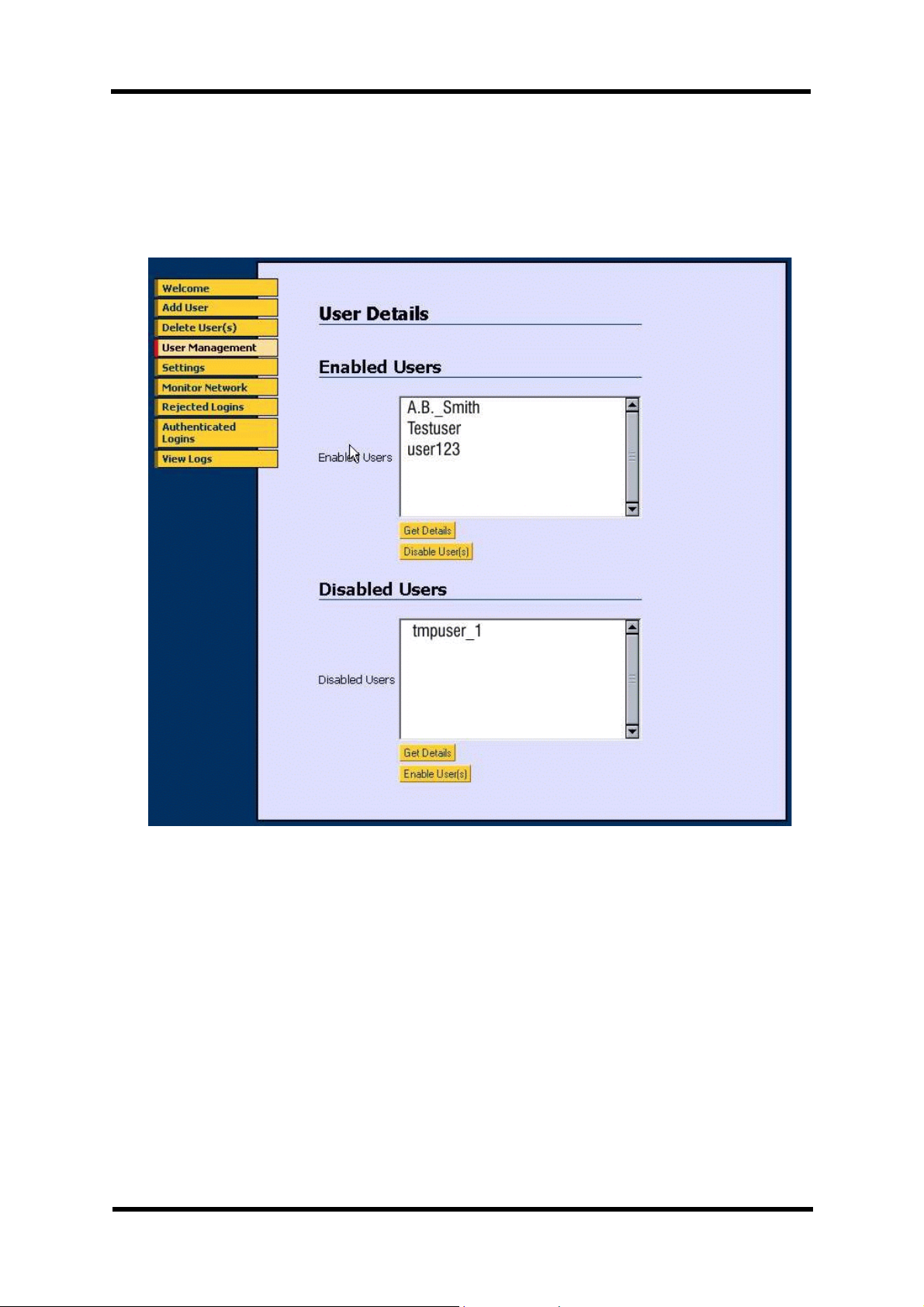
5.2 Managing Users.
If it is only required to temporarily enable or disable users, then the [User
Management] menu may be used for this purpose. This management feature
does not remove users from the system.
The [User Management] menu displays two windows, one listing the currently
enabled users who are allowed access to the network, and the second window
listing users that are currently denied access.
To obtain more information about a user:
! Select the user by clicking on the user’s displayed name.
! Click the [Get Details] button.
! The information from the User’s certificate is then displayed to the
Administrator.
Page 32 of 53 NGCD000423.005 NanoGlobes Ltd

WLAN-Minder User Manual
To Enable a disabled user:
} Select the user from the DISABLED window by clicking on the users
displayed name.
} Click the [Enable User] button.
} The selected user status will change to “Enabled” and his name will now
appear in the ENABLED Window.
To Disable an enabled user:
} Select the user from the ENABLED window by clicking on the user’s
displayed name.
} Click the [Disable User] button.
} The selected user status will change to “Disabled” and his name will now
appear in the DISABLED Window.
NanoGlobes Ltd NGCD000423.005 Page 33 of 53

WLAN-Minder User Manual
5.3 Monitoring the Network.
The WLAN-Minder will allow an Administrator to view the identity of the users
who are currently authenticated on the network in real time. To view these users
the [Monitor Network] option should be chosen from the “Welcome” menu.
The users listed in the displayed window are those users currently authenticated
in the Wireless Network.
To obtain more information about a user:
} Select the user by clicking on the user’s displayed name.
} Click the [Get Details] button.
} The information from the User’s certificate is then displayed to the
Administrator.
To Disable an authenticated user:
! Select the user from the window by clicking on the user’s displayed name.
! Click the [Disable User] button.
NOTE: This does NOT log the user off from the network. It flags the
user as disabled so that the next time he attempts to login or reauthenticate to the network he will be denied access.
Page 34 of 53 NGCD000423.005 NanoGlobes Ltd

WLAN-Minder User Manual
5.4 Monitoring Logins.
The Administrator may view a history of the Authenticated and Rejected logins
that have been attempted by users of the WLAN-Minder system. These logs
may be viewed by clicking on the [Rejected Logins] or [Authenticated Logins]
buttons displayed on the “Welcome” screen.
Rejected Login information.
} Date: Login was attempted
} Time: Login was attempted
} Reason for failure: i.e. Login Incorrect
} User name: The name of the user attempting the
connection
(e.g. anonymous)
} Client: Refers to the Access Point name making the
request to the WLAN-Minder (e.g. “rheadr” )
} MAC: The Media Access Control of the user’s WLAN
adapter card attempting the connection to the
LAN. (e.g. 000a8aa2ac08)
Authenticated Login information.
} Date: Date when Login was attempted
} Time: Time when Login was attempted
} User name: The name of the authenticated user
NanoGlobes Ltd NGCD000423.005 Page 35 of 53

WLAN-Minder User Manual
5.5 Viewing a User Token.
The Administrator may view certain information on a user’s smart card or
eToken. The information displayed will indicate the user’s name and list the
Access Points he has rights to associate with.
Select [User Management] option of the system menu. Select the type of token
that is to be read, (either smart card or eToken). At the “User PIN” prompt, enter
the PIN for the selected token, then click the [View Token] button for the
information to be displayed.
Page 36 of 53 NGCD000423.005 NanoGlobes Ltd

WLAN-Minder User Manual
5.6 Backing Up the WLAN-Minder Configuration Files.
• Insert a 32MB Smart Media device into the slot on the rear panel of the
WLAN-Minder unit. (See {11} Section 1.4)
• Reset the WLAN-Minder unit. Either cycle the power Off/On, or depress
and release the Reset switch on the rear panel of the WLAN-Minder unit
(See {12} Section 1.4 ).
• Login in to the WLAN-Minder unit using the Administrator smart card.
• Select the [System Settings] option from the main menu.
• Scroll down the screen to the Backup/Restore section.
• Click on the [Backup System to Smart Media] button to start the backup
process.
• Once the backup process has completed, the [Back] button should be
clicked to return control to the main system menu.
The WLAN-Minder supports a Smart Media interface, allowing the configuration
files for the server to be backed up. The backup files stored on the smart media
device contain the confidential security information of the WLAN-Minder,
therefore care should be taken to store the Smart Media backups in a secure
location.
NanoGlobes Ltd NGCD000423.005 Page 37 of 53

WLAN-Minder User Manual
The following figures give a rough guide to the storage requirements for a
system back up.
25 Users Backup size 1.5Mb
50 Users Backup size 1.8Mb
100 Users Backup size 2.2Mb
A 32MB Smart Media device is capable of storing a number of backup images.
Page 38 of 53 NGCD000423.005 NanoGlobes Ltd
WLAN-Minder User Manual
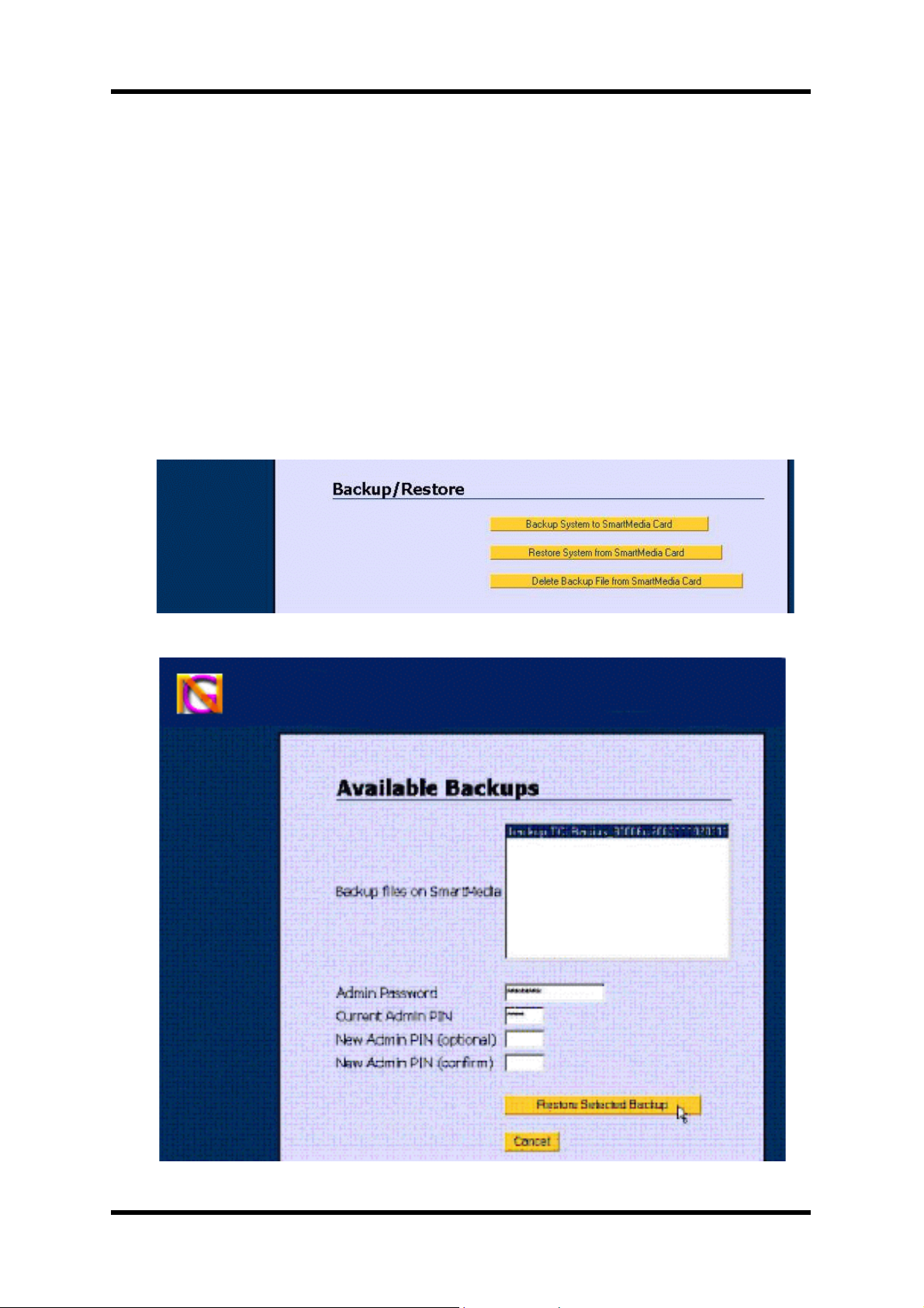
5.7 Restoring a WLAN-Minder Configuration.
• Insert the 32MB Smart Media device that contains the configuration files
into the slot on the read panel of the WLAN-Minder unit. (See {11}
Section 1.4)
• Reset the WLAN-Minder unit. Either cycle the power Off/On, or depress
and release the Reset switch on the rear panel of the WLAN-Minder unit
(See {12} Section 1.4).
• Login in to the WLAN-Minder unit using the Administrator smart card.
• Select the [System Settings] option from the main menu.
• Scroll down the screen to the Backup/Restore section.
• Click on the [Restore System from Smart Media Card] button.
• A list of the backup files present on the Smart Media card is displayed.
NanoGlobes Ltd NGCD000423.005 Page 39 of 53

WLAN-Minder User Manual
Each backup is labelled with the WLAN-Minder name that the backup was
made from and the date and time the backup was made.
E.g. NGLMinder_80006c_20031110203145
CCYYMMDDhhmmss
CC Century
YY Year
MM Month
DD Day
hhmmss Hours:Mins:Secs
• WARNING Restoring a configuration file will DELETE all
configuration and USER files currently stored on the
WLAN-Minder unit.
• The administrator should select the backup file to restore by clicking on
the appropriate file, so that it becomes highlighted.
• The administrator must then enter the Administrator Password, and the
PIN for the administrator card currently inserted in the Admin card slot of
the WLAN-Minder unit. (An option is given to the Administrator to change
the PIN of the Admin card if required).
• Click the [Restore Selected Backup] button to start the restore process.
NOTE: The restore process will delete all user files currently on the
WLAN-Minder unit and will replace them by the user files read
from the backup media.
} Once the backup process is completed the unit will restart itself.
} It is recommended that the administrator then delete the log files on the
restored system, so that the log file presents a valid status history of the
newly restored unit.
Page 40 of 53 NGCD000423.005 NanoGlobes Ltd

WLAN-Minder User Manual
5.8 Changing the System Time / Date.
Care must be taken when changing the system time and date. Certificates are
issued to users with a specific expiry date. The WLAN-Minder unit uses its own
clock to determine whether a user’s certificate has expired or not. Thus, if an
invalid date/time is set (i.e. an incorrect year) it may cause ALL users to be
rejected, as the WLAN-Minder would believe that all user certificates had expired
according to the date currently set in its calendar/clock.
} To update the time or date the administrator must login to the WLAN-
Minder unit with their administrator smart card.
} From the main system menu select the [System Settings] option.
} Scroll down the screen to the [Date and Time] section.
} ALL the date and time parameters MUST be entered, each parameter
being just TWO Digits.
Day: 01....28, 29, 30, 31
Month: 01....12
Year: 03....99
Hours: 00....23
Minutes: 00....59
} With all the parameters entered click the [Update Time] button to reset
the Real Time Clock of the WLAN-Minder Unit.
NanoGlobes Ltd NGCD000423.005 Page 41 of 53

WLAN-Minder User Manual
6 Appendices
6.1 Hardware Specification
Processor ARM940T
Memory: 4MBytes FLASH EEPROM
8M Bytes NAND EEPROM
32M Bytes SDRAM
Network: LAN Port 10/100Base T RJ45 (Full Duplex)
WLAN Port 10/100Base T RJ45 (Full Duplex) [OPTIONAL N/A]
Network
LAN Status: Link GREEN LED On indicates link to hub/switch is
Data YELLOW LED On indicates presence of traffic on LAN
established.
port.
WLAN Status:Link GREEN LED On indicates link to hub/switch is
established.
Data YELLOW LED On indicates presence of traffic on LAN
port. [OPTIONAL N/A]
Serial I/O RS232 BIOS Admin Port.
RS232 Interface: RxD, TxD, RTS, CTS, Gnd
ESD Protection on I/O lines.
Baud Rate: 57600
Data Bits 8
Stop Bits 1
Flow Control None
USB Device v1.1 [OPTIONAL N/A]
System
Indicators: Power RED LED Lit when 5VDC power is present at the
unit.
Administrator
Smart card Bi Colour LED GREEN Flashing - prompt for user to
insert Smart card.
RED - Indicates Card inserted and
Power applied.
User
Smart card Bi Colour LED GREEN Flashing - prompt for user to
insert Smart card.
RED - Indicates Card inserted and
Power applied.
Page 42 of 53 NGCD000423.005 NanoGlobes Ltd

WLAN-Minder User Manual
Administrator
USB Socket GREEN LED Flashing - prompt for user to insert
eToken.
User
USB Socket GREEN LED Flashing - prompt for user to insert
eToken.
Smart Card
Interfaces: Administrator ISO 7816 compliant
User ISO 7816 compliant
USB eToken
Interfaces: Administrator USB v2 (Low & High speed supported)
User USB v2 (Low & High Speed supported)
SmartMedia: Supports up to 32MB devices.
Real Time
Clock: Battery backed up Real Time Clock storing date and time.
Y2K compliant.
Power
Connector: DC Power Jack 2.1mm
Input
Supply
Voltage: +5VDC
Power: 6500mW Typical
Power
Adapter: 100 ~ 240VAC @ 0.2A Output 5VDC @ 1.7A
Unit Size: 195mm x 135mm x 48mm (Overall Dimensions)
Unit Weight: 1.52Kg
Packaging
Size: 265mm x 270mm x 130mm
NanoGlobes Ltd NGCD000423.005 Page 43 of 53
WLAN-Minder User Manual
6.2 Connector Pin-out.
RS232 9-Way D-Type Male Pin Out
(Administrator RS232 Connector)
Pin Signal I/O Pin Signal I/O
1 n/c 6 n/c
2 Receive Data I/P 7 Request To Send O/P
3 Transmit Data O/P 8 Clear To Send I/P
4 n/c 9 n/c
5 Signal Ground —
10/100Base-T RJ45 Connector Pin Out
Pin Signal I/O Pin Signal I/O
1 Transmit (+) O/P 5 n/c
2 Transmit (-) O/P 6 Receive (-) I/P
3 Receive (+) I/P 7 n/c
4 n/c 8 n/c
Page 44 of 53 NGCD000423.005 NanoGlobes Ltd
WLAN-Minder User Manual
6.3 BIOS Administrator cable [NGL-210] pin-out.
RS232 Administration Cable NGL-210 Pin Out.
9-Way D-Type
Female
DCD -----> 1 <------------------------> 1 <----- DCD
RxD | 2 <------------------------> 3 | TxD
TxD | 3 <------------------------> 2 | RxD
DTR | 4 <------------------------> 6 <----- DSR
Gnd | 5 <------------------------> 5 Gnd
DSR ------> 6 <------------------------> 4 DTR
RTS 7 <------------------------> 8 CTS
CTS 8 <------------------------> 7 RTS
RI 9 n/c 9 RI
9-Way D-Type
Female
NanoGlobes Ltd NGCD000423.005 Page 45 of 53

WLAN-Minder User Manual
6.4 Windows Hyper-Terminal Setup for BIOS
Administration.
} At the PC run the Hyper Terminal Program (or similar terminal emulator
program).
} Click the [Start] button through to:
Programmes–>Accessories–>Communications–>HyperTerminal
} Enter a name for the connection i.e. “WLAN-Minder”
} Select the correct COM port through which to establish the connection.
} Set the Serial Port Parameters to:
Bits per Second 57600bps
Data Bits 8
Parity None
Stop Bits 1
Flow Control None
} Once the above parameters have been set click the [OK] button.
} Hyper-Terminal is now configured with the correct parameters and is
ready to operate as a terminal emulator for the WLAN-Minder unit.
Page 46 of 53 NGCD000423.005 NanoGlobes Ltd

WLAN-Minder User Manual
6.5 Unblocking a Blocked Smart Card / eToken.
} Please contact your re-seller or distributor to obtain the necessary
software required to unblock a smart card or eToken.
NanoGlobes Ltd NGCD000423.005 Page 47 of 53

WLAN-Minder User Manual
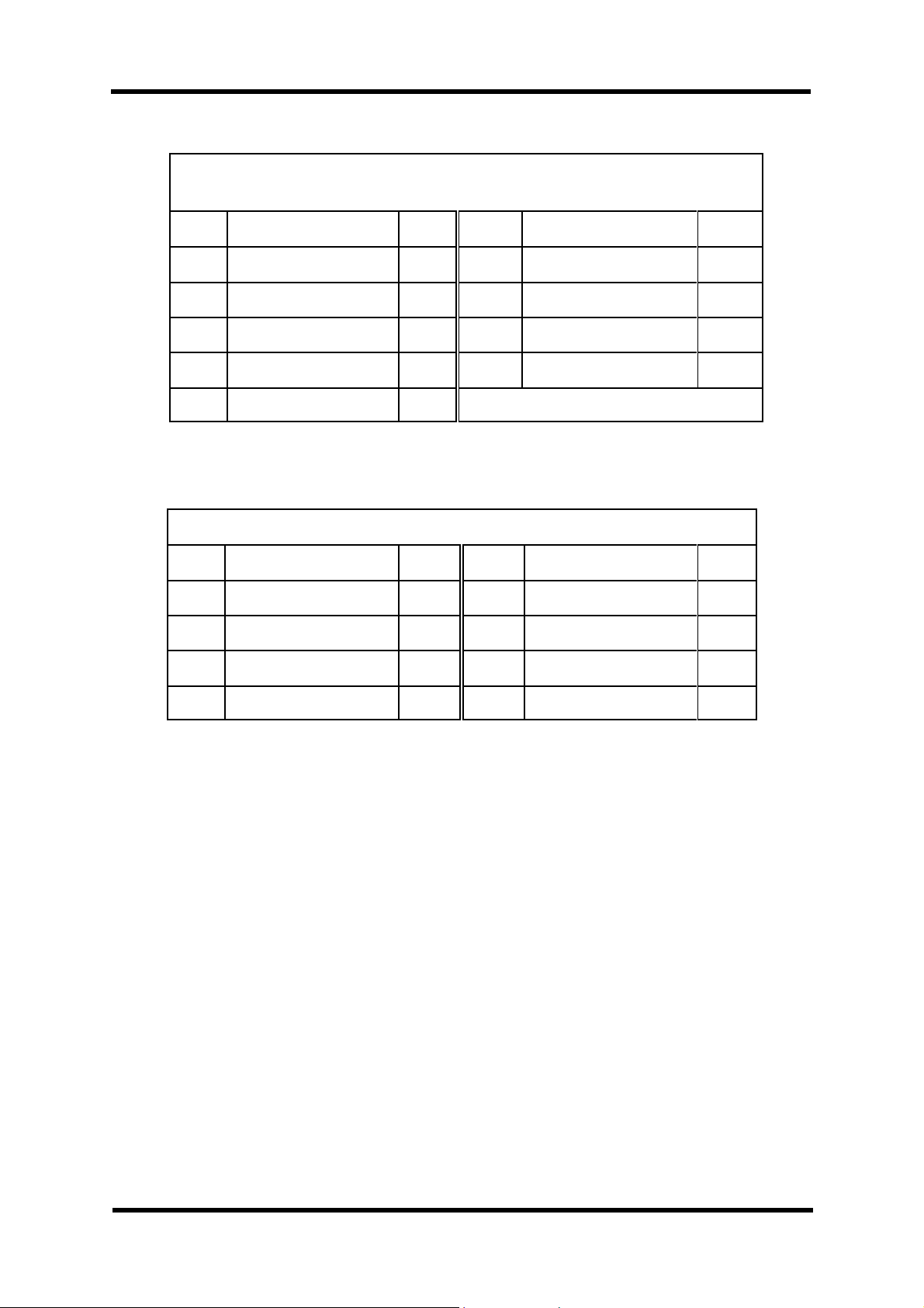
6.6 Two Character Country Codes.
AD Andorra
AE United Arab Emirates
AF Afghanistan
AG Antigua and Barbuda
AI Anguilla
AL Albania
AM Armenia
AN Netherland Antilles
AO Angola
AQ Antarctica
AR Argentina
AS American Samoa
AT Austria
AU Australia
AW Aruba
AZ Azerbaidjan
BA Bosnia-Herzegovina
BB Barbados
BD Banglades
BE Belgium
BF Burkina Faso
BG Bulgaria
BH Bahrain
BI Burundi
BJ Benin
BM Bermuda
BN Brunei Darussalam
BO Bolivia
BR Brazil
BS Bahamas
BT Buthan
BV Bouvet Island
BW Botswana
BY Belarus
BZ Belize
CA Canada
CC Cocos (Keeling) Isl.
CF Central African Rep.
CG Congo
CH Switzerland
CI Ivory Coast
CK Cook Islands
CL Chile
CM Cameroon
CN China
CO Colombia
CR Costa Rica
CS Czechoslovakia
CU Cuba
CV Cape Verde
CX Christmas Island
CY Cyprus
CZ Czech Republic
DE Germany
DJ Djibouti
DK Denmark
DM Dominica
DO Dominican Republic
DZ Algeria
EC Ecuador
EE Estonia
EG Egypt
EH Western Sahara
ES Spain
ET Ethiopia
FI Finland
FJ Fiji
FK Falkland Isl.(Malvinas)
FM Micronesia
FO Faroe Islands
FR France
FX France (European Ter.)
GA Gabon
GB Great Britain (UK)
GD Grenada
GE Georgia
GH Ghana
GI Gibraltar
GL Greenland
GP Guadeloupe (Fr.)
GQ Equatorial Guinea
GF Guyana (Fr.)
GM Gambia
GN Guinea
GR Greece
GT Guatemala
GU Guam (US)
GW Guinea Bissau
GY Guyana
HK Hong Kong
HM Heard & McDonald Isl.
HN Honduras
HR Croatia
HT Haiti
HU Hungary
ID Indonesia
IE Ireland
IL Israel
IN India
IO British Indian O. Terr.
IQ Iraq
IR Iran
IS Iceland
IT Italy
JM Jamaica
JO Jordan
JP Japan
KE Kenya
KG Kirgistan
KH Cambodia
KI Kiribati
KM Comoros
KN St.Kitts Nevis Anguilla
KP Korea (North)
KR Korea (South)
KW Kuwait
KY Cayman Islands
KZ Kazachstan
LA Laos
LB Lebanon
LC Saint Lucia
LI Liechtenstein
LK Sri Lanka
LR Liberia
LS Lesotho
LT Lithuania
LU Luxembourg
LV Latvia
LY Libya
MA Morocco
MC Monaco
MD Moldavia
MG Madagascar
MH Marshall Islands
ML Mali
MM Myanmar
MN Mongolia
MO Macau
MP Northern Mariana Isl.
MQ Martinique (Fr.)
MR Mauritania
MS Montserrat
MT Malta
MU Mauritius
MV Maldives
MW Malawi
MX Mexico
MY Malaysia
MZ Mozambique
NA Namibia
NC New Caledonia (Fr.)
NE Niger
NF Norfolk Island
NG Nigeria
NI Nicaragua
NL Netherlands
NO Norway
NP Nepal
NR Nauru
NT Neutral Zone
NU Niue
NZ New Zealand
OM Oman
PA Panama
PE Peru
PF Polynesia (Fr.)
PG Papua New
PH Philippines
PK Pakistan
PL Poland
PM St. Pierre & Miquelon
PN Pitcairn
Page 48 of 53 NGCD000423.005 NanoGlobes Ltd

WLAN-Minder User Manual
PT Portugal
PR Puerto Rico (US)
PW Palau
PY Paraguay
QA Qatar
RE Reunion (Fr.)
RO Romania
RU Russian Federation
RW Rwanda
SA Saudi Arabia
SB Solomon Islands
SC Seychelles
SD Sudan
SE Sweden
SG Singapore
SH St. Helena
SI Slovenia
SJ Svalbard & Jan Mayen
Is
SK Slovak Republic
SL Sierra Leone
SM San Marino
SN Senegal
SO Somalia
SR Suriname
ST St. Tome and Principe
SU Soviet Union
SV El Salvador
SY Syria
SZ Swaziland
VN Vietnam
VU Vanuatu
WF Wallis & Futuna Islands
WS Samoa
YE Yemen
YU Yugoslavia
ZA South Africa
ZM Zambia
ZR Zaire
ZW Zimbabwe
TC Turks & Caicos Islands
TD Chad
TF French Southern Terr.
TG Togo
TH Thailand
TJ Tadjikistan
TK Tokelau
TM Turkmenistan
TN Tunisia
TO Tonga
TP East Timor
TR Turkey
TT Trinidad & Tobago
TV Tuvalu
TW Taiwan
TZ Tanzania
UA Ukraine
UG Uganda
UK United Kingdom
UM US Minor outlying Isl.
US United States
SY Uruguay
KZ Uzbekistan
VA Vatican City State
VC St.Vincent & Grenadines
VE Venezuela
VG Virgin Islands (British)
VI Virgin Islands (US)
NanoGlobes Ltd NGCD000423.005 Page 49 of 53

WLAN-Minder User Manual
7 References
7.1 WLAN-Minder Workstation Client Users Manual.
Document NGCd000421
Page 50 of 53 NGCD000423.005 NanoGlobes Ltd

NOTES:
WLAN-Minder User Manual
NanoGlobes Ltd NGCD000423.005 Page 51 of 53

NOTES:
WLAN-Minder User Manual
Page 52 of 53 NGCD000423.005 NanoGlobes Ltd

 Loading...