

Page 1
1
Notice de conduite
Instruction manual
Manuale d'istruzione
Betriebsanleitung
Instructieboek
Manuale de instrucciones
Instruksjonbok
Käyttöohje
P/N 970 312 491
Page 2

2
CONTENTS
1. SAFETY INFORMATION
2. GENERAL INFORMATION
3. ENGINE IDENTIFICATION
• Identification of main components
4. PREPARATION PRIOR TO RUNNING
5. ENGINE OPERATIONS
• Switching on
• Switching off
• Running in / Servicing under guarantee
• List of guarantee check operations
6. MAINTENANCE
• Draining engine oil
• Replacing oil filter
• Fuel filter replacement
• Nozzle holder replacement
• Flushing cooling system
• Replacing water pump
• Electrical/battery equipment
• Adjusting valve clearance
• Reverse reduction gear
• Recommendations
• Periodic Maintenance schedule
• Technical features
• Recommended onboard equipment
*All information and specifications contained in this
manual are based on the technical data in use at the
time of publication.
1 – SAFETY INFORMATION
This operating manual was compiled to help you get
the most out of your engine and its ancillary equipment. It contains important instructions which should
be observed when the engine is running.
It is extremely important that it is read by the
user. It should be always kept in the same location as the engine.
SAFETY SYMBOLS
These symbols are used to indicate that a danger
exists. They are aimed at drawing your attention to
components or operations that could be dangerous
for yourself or other persons using the engine.
Please read the recommendations they contain carefully. It is highly important that you read the safety
instructions and rules before running engine.
I DANGER
Means that an extremely serious danger which could
result in death or major disability if the appropriate
specific measures are not taken.
I WARNING
Means that a danger exists which could cause injury
or death if the appropriate specific measures are not
taken
I CAUTION
Acts as a reminder that safety measures need to be
observed, or draws attention to dangerous actions
which could cause personal injury or damage to the
vessel or its components.
The user should take all necessary precautions in
terms of handling and protection and should seek
advice from a sector professional.
Non-respect of the safety instructions could lead to:
Bodily danger, a danger of environmental pollution
(dangerous substance leaks), danger to equipment
that could cause essential engine operation malfunctions.
• FOLLOW ALL SAFETY RECOMMENDATIONS
- Comply with the engine's warning and caution stickers
- Remove the ignition key and close the battery cut-out
before working on the engine or its ancillary equipment
- Close the engine casing and replace all protective
parts before starting the engine
- Always kept the working area around the engine clean
and uncluttered
- Keep all inflammable liquids outside the engine compartment
- Never run the engine when under the influence of alcohol or medicines
• WEAR PROTECTIVE CLOTHING
- To avoid bodily injury, keep clear of rotating parts and
do not wear loose clothing near the engine when it is
running.
- Use safety clothing and equipment, protective goggles,
gloves, etc. in accordance with circumstances and
when they are required.
• FUELS AND LUBRICANTS
- Switch off the engine before re-fuelling or adding lubrication products
- Do not smoke or use naked flame during re-fuelling
- Wear gloves when looking for a possible leak
- Hot oil can cause burns – let the engine cool before
checking the oil level, or changing the oil or oil filter cartridge
- Always use NANNI DIESEL recommended fuels and
lubricants
ENGLISH
Operating and maintenance manual
Page 3
3
EXHAUST FUME PRECAUTIONS
- Only run the engine away from people and animals
in a well ventilated area–a build-up of exhaust fumes
can be noxious
PRESSURE
- Never open the cooling system cap or oil filler cap
when the engine is running or while it is still hot. Release all pressure in the systems before removing the
caps
- Never check for possible pressure leaks with your
bare hands – wear gloves – leaks of liquids under
pressure can cause serious injuries – in the event of
injury due a liquid leak, see a doctor immediately
BATTERY
- An extremely explosive and volatile oxyhydrogen
gas mixture is created when the battery is being recharged. Never smoke, take a naked flame or cause
a spark near to the battery
- Never short circuit the battery terminals
- The electrolyte in the battery is highly corrosive –
wear gloves and safety goggles.
ELECTRICAL WIRING
- Disconnect the engine ignition and the battery cutout before working on the electrical equipment
- Check the condition of the electrical cables and wiring – short circuits can create a fire hazard
DISPOSAL OF WASTE FLUIDS
- The various fluids used to operate the engine create
a health hazard. Make sure you read the instructions
shown on each product's packaging.
- Comply with the environmental regulations relating
to the disposal of old oil, fuel, cooling liquid, filters
and batteries.
2 –GENERAL INFORMATION
Your NANNI DIESEL engine has been carefully researched and manufactured to the highest quality by
NANNI INDUSTRIES. It is built in accordance with
very precise specifications out of the very finest materials and following strict production procedures.
Your NANNI DIESEL en gi ne i s a reliable and long
term power unit for your vessel.
The installation of your engine in your vessel is highly
important in terms of correct power boating and environmental protection.
NANNI INDUSTRY engineers are among the most
skilful in the sector. Their experience, knowledge
of the sea and mastery of techniques in association with that of engineers from MAN, KUBOTA
and TOYOTA guarantees you the best there is in
terms of performance/reliability economy.
WARNING: It is imperative that you engine is in-
stalled in a Shipyard or by a representative of
NANNI INDUSTRIES, and in compliance with the
installation instructions.
This operating manual contains all the information
required for your engine to operate correctly.
Represented in more than 50 countries via its network of agents and retailers, NANNI INDUSTRIES
guarantees your plain sailing World-wide. Parts, labour or just advice, everything has been thought out
to serve you.
Do not hesitate to contact your nearest NANNI DIESEL approved retailer .
We wish you calm seas and fair weather.
Please read this manual carefully before using your
engine.
Follow all safety recommendations.
I WARNING: Correct operation of your marine en-
gine is dependent on a usage that conforms to the
engine's definition and its transmission (type of vessel, speeds and operating conditions.)
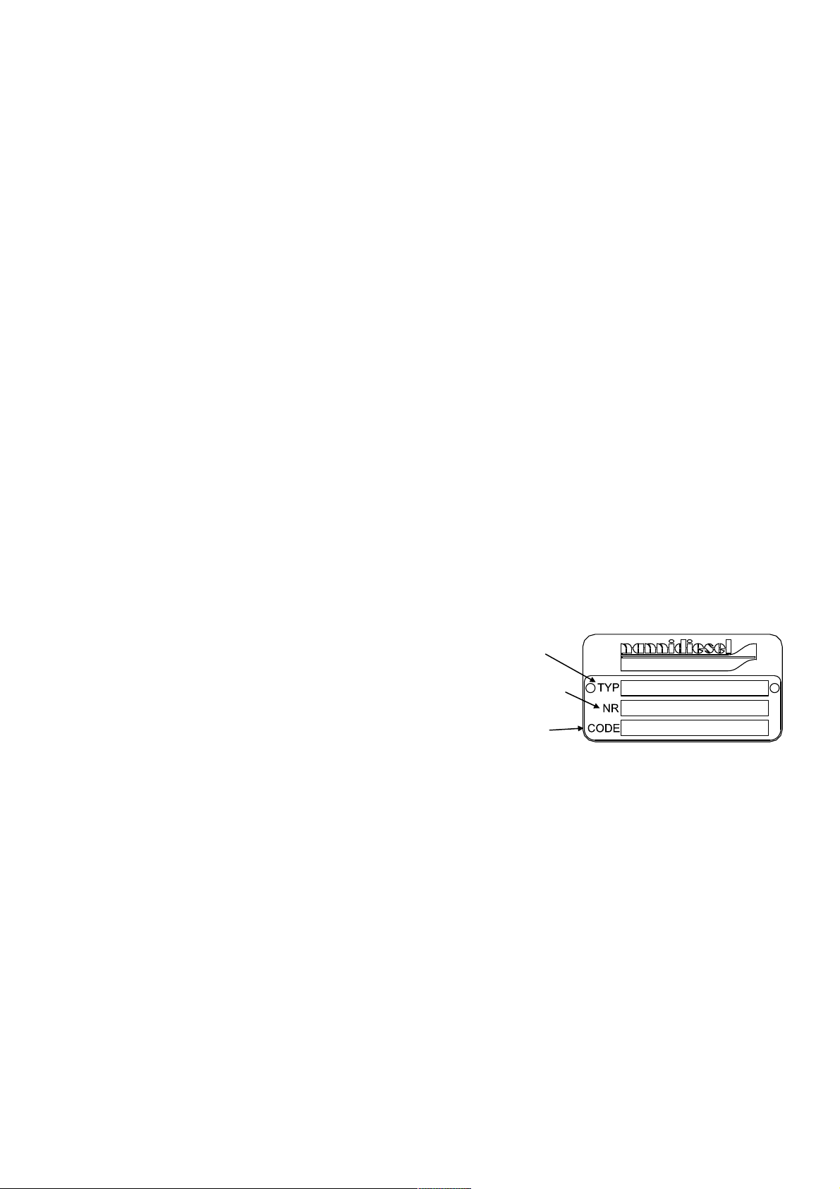
3 – ENGINE IDENTIFICATION
It is imperative that the references shown on the
plates attached to the engine and reversing gear are
quoted in all correspondence, information requests
and orders for spare parts.
IMPORTANT: Make a note of the engine and trans-
mission serial numbers, and the model type, and
keep in a safe place
ENGINE TYPE
SERIAL NUMBER
SPECIFICATION
Page 4

4
IDENTIFICATION DES PRINCIPAUX ORGANES
1. Heat exchanger
2. Cooling liquid filler hole
3. Block drain plug
4. Clear water pump
5. Sea water pump
6. Alternator
7. Flexible fastening
8. Electrical connector
9. Starter
10. Oil gauge
11. Oil filler hole
12. Air filter
13. Water injector exhaust elbow
14. Anode
15. Oil filter
16. Oil pressure transmitter
17. Reversing gearbox reduction gear
18. Injector pump
19. Electrical cut-out
20. Accelerator
21. Air cooler
22. Turbo
23. Exchanger drain
24. Thermostat
25. Turbo drain tap
26. Condensation drain hole
27. Battery minus (-) cable connector
28. Air re-heater relay
29. Diesel filter and water contamination detector air
30. Starter relay
31. Hydraulic oil tank (Stern drive version)
32. Power steering oil coolant (Stern drive version)
33. Neutral safety contact
34. Oil drain port
4 - PREPARATION PRIOR TO RUNNING
When the engine has been installed on board the
vessel and prior to removing the protective covers
over the various openings, clean the engine's surfaces. These operations should be carried out by a
Shipyard or an approved workshop.
GENERAL CHECKS.
See SILVERWAKE® guarantee conditions
- Fill engine and reversing gear with oil
- Fill the exchanger with coolant, degas the turbo volute casing at the highest point
- Check belt tensions
- Check that the various connectors and plugs are
tight (water and oil)
- Check electrical spade connectors, battery terminals, cut-out and extension connectors are tight, plus
the battery electrolyte levels
- Accelerator control.
- Check that the “accelerator and reversing gear”
lever is correctly synchronised (imperative in the case
of a single cable level control.) You should have finished de-clutching we you start to accelerate. In the
event of electrical controls, refer to the specific controls manual provided.
- Carry out a final check on fixing and a visual check
of the marine unit. If necessary, retouch the paintwork on the unit and accessories.
I DANGER :
Never take a naked flame or cause a spark near to
the battery. An extremely explosive and volatile oxyhydrogen gas mixture is created when the battery is
being re-charged - Never cause a short circuit.
Battery electrolyte is highly corrosive: if this acid
come into contact with the skin, wash immediately in
soapy water – in the event that it splashes into the
eyes, rinse abundantly with water and contact a doctor immediately.
- When connecting the battery cable, start with the
positive terminal
- When disconnecting the battery cable, start with the
negative terminal
I WARNING:
Do not drop fuel or lubricants onto the engine
The fluids used to operate the engine create are a
health hazard.
Engine oil cold be harmful to the skin– wear gloves
NOTE: Modern diesel engines are high performance
units which require high quality fuels and lubricants.
ENGINE AND REVERSING GEARBOX LUBRICATION
Engine
Oil pump greasing system, release valve pressure
regulation
Disposable oil filter cartridge
Transmission
See separate specifications
Engine oil levels
Unscrew the oil filler hole cap located on the
rocker cover. Check the oil level using the dipstick. Never fill beyond the maxi level.
NOTE: Oil types and quantities are given in the technical feature table
FUEL SYSTEM
Composition
Disposable main filter cartridge
Injector pump
High pressure injector pipe
Injectors (inside the cylinder head)
ENGLISH
Page 5

5
Fuel system purge
- Check the fuel level in the tank.
- Open the fuel cock, unscrew the purge screw located on the upper part of the filter and pump the system using the incorporated pump. When no more air
bubbles appear, tighten the screw. In the event that
the injection system is not fully primed, carry out the
following procedure:
- Unscrew the No. 1 injector fuel pipe and turn the
engine on the starter until diesel fuel appears. Retighten the nut and follow out the same procedure for
the other injectors.
- Re-start the engine and check for leaks.
I DANGER : Do not smoke, approach with a naked
flame or cause a spark. Wipe up any spilt fuel.
COOLING SYSTEM
This is made up of two different systems: the sealed
cooling system and the sea water cooling system.
Sealed cooling system
This is made up of a pump driven by the crankshaft
via two V shaped belts, a water temperature heat
exchanger, an oil temperature heat exchanger integrated unto the engine block and a thermostat.
Seawater cooling system
This is made up of a pump, a clear - salt water heat
exchanger, supercharger air refrigerant, power steering oil refrigerant (version Stern drive), reversing gear
oil exchanger and an exhaust elbow.
Coolant
Recommendations for initial start up.
- Check that the drain plug located beneath the turbo,
open the breather plug on the top of the turbo liner.
- Create a diluted 50% antifreeze and 50% clear water antifreeze mixture. The quantity required is given
in the table of technical specifications.
- Pour the mixture into the filler hole, close the
breather plug on the top of the turbo liner when the
liquid can be seen and continue filling up to the maximum. Possible top-ups should be made when the
engine is cold and only with clear water. Re-start the
engine and top-up to correct level. Check for leaks.
- Every two years at the beginning of the season,
completely drain the cooling system, flush out using
clear water and re-fill in accordance with the instructions provided above,. (See SILVERWAKE guarantee
terms.)
I
DANGER : Always fill the cooling system when
the engine is off and cold – Do not smoke or approach with a naked flame.
- Keep away from revolving parts when the engine is
running
.
I CAUTION : Never use undiluted antifreeze. The
use of additives and other type of coolant can cause
insulating deposits to be formed, and engine overheating.
Hot water connection
You can install an onboard hot water system by connecting from the interior clear water system to the
engine (Ask your NANNIDIESEL agent).
I CAUTION: Before staring the engine, make sure
that the sea water inlet is open as it only needs the
pump to run dry for several seconds in order to cause
deterioration to the water pump rotor.
After cleaning the sea water filter, carefully close the
cover in order to avoid the water pump sucking in air.
ELECTRICAL EQUIPMENT
5. ENGINE OPERATION
RUNNING
I
DANGER : Make sure that the engine casing is
correctly closed and install all the protective
items before starting the engine.
- Check the fuel level
- Open the diesel supply tap
- Open the sea water inlet valve
- Check engine and transmission oil levels
- Check the coolant level
- Close the battery isolation switch
I CAUTION: Turning the key to the contact position
when starting-up commences the process of preheating inlet air to the engine which can continue
whilst running for approximately 6 minutes. Take
care not to let any part of the body come into contact
with the air pre-heating zone of the engine.
Inlet air pre-heating continues whilst the engine temperature is less than 40°C.
Wiring positions / Color / Function
1 Red (+)12 volt battery
2 Violet D+ Alternator D+ Terminal
3 Grey Oil pressure sensor
4 Yellow Heating unit
5 Pink/Black Oil pressure switch
6 Yellow/Green Water temperature switch
7 Brown Starter
8 Orange/Blue Water temperature sensor
9 Green Water temperature indicator probe
10 Red/Yellow Engine stop solenoid power supply
11 Dark blue (-) engine speed indicator sensor
12 Dark blue (+) engine speed indicator sensor
13 Light blue Water contaminated diesel indicator
14 unused
15 Black (-) 12 volt battery
16 unused
Page 6

6
- Check warning lights and other functions once the
engine has started.
- Stop the engine immediately if the alarm keeps ringing, if the temperature rises abnormally, or if several
warning lights stay lit
.
I CAUTION : Discover and solve the problem be-
fore starting the engine!
Check that the seawater is running through the exhaust correctly.
Let the engine idle for 2 to 3 minutes, then subject it
to a load straightaway.
If the engine does not start at the first attempt, try
again making sure to switch off between each attempt.
IMPORTANT:
In the event of several unsuccessful attempts at starting the engine, look for the reason.
Do not keep on trying as water could be sucked into
the engine through the exhaust system!
I WARNING: Never switch of the electrical system
using the battery cut-out whilst the engine is still running as this could cause damage to the alternator.
IMPORTANT: Do not let the engine idle unnecessarily without load.
STOPPING THE ENGINE
- Move the lever to the idle/neutral position
- Let the engine idle for few seconds so that the temperatures and turbo speed can stabilise.
- Never accelerate the engine before switching
off.
- Turn the key to the "O" position (vertical.)
- Switch of the battery isolation switch, close the sea
water inlet valve as well as the fuel supply.
IMPORTANT: In the event of the vessel being towed,
stop the engine and ensure that the seawater inlet
valve is close so that the engine does not accidentally
fill up with seawater.
TWIN ENGINE VESSELS:
In the event of running on only one engine, close the
sea water inlet of the stopped engine. Do not forget
to re-open it before re-starting the engine.
I CAUTION : Check the engine and the engine
compartment for possible leaks.
RUNNING IN
SERVICING UNDER GUARANTEE
Running in
We recommend that for the first 20 hours of running
you treat your engine gently and only run it at maximum speed for very short periods.
Never race the engine immediately after starting without having let it warm up first.
IMPORTANT : After running, the engine should not
be constantly run at its maximum speed but at 200
RPM below its maximum speed
.
Servicing under guarantee
All preventive maintenance operations as well as
their timescale are given in the: SILVERWAKE. ®
Guarantee Booklet
The guarantee is conditional on these servicing operations. They must be carried out by an approved
NANNI DIESEL representative
All new engines are guarantee against all component
defects in accordance with the terms laid down in the
SILVERWAKE. ® Guarantee Booklet which is given
to the purchaser when the engine is delivered.
6. MAINTENANCE
I DANGER: To avoid any bodily injury, let the en-
gine cool and close the battery isolation switch before
carrying out any work.
Observe safety and environmental protection recommendations
IMPORTANT : These recommendations are vital.
Compliance will lengthen your engines operational
life and ensure that the conditions necessary for
meeting the normal guarantee terms are fulfilled.
Do not make any unapproved modifications to the
engine.
Damage caused by the use of unlisted or non approved spare parts is not covered under the terms of
the guarantee.
All interventions and maintenance work should be
carried out by an approved NANNI DIESEL workshop
If the engine is used for a number of hours that is
less than the indicators provided, maintenance
should be carried out once a year.
In this case, we recommend that maintenance work is
carried out before laying up for the winter, the engine
will then be protected by new, clean lubrication oil.
This does not obviate the wintering operations laid
down in the SILVERWAKE guarantee.
Valve clearance adjustment
This work should be carried out by a specialist workshop (calibrated adjustment shims)
Timescale: in accordance with the maintenance table
(see values in the table of technical features)
ENGLISH
Page 7

7
Water pump rotor replacement
- Close the sea water inlet valve
- Remove the water pump cover
- Remove the worn rotor using adjustable pliers
- Clean remaining components.
- Install a new rotor
- Replace the water pump cover using a new seal.
- Open the sea water inlet valve
- Start the engine and check the system for leaks
Electrical equipment
Regularly check alternator belt tension. Tighten the
belt between the pulleys (190 Nm using the DENSO
checking instrument).
I DANGER : Stop the engine and turn of the battery
isolation switch before doing any work on the electrical system.
Battery
Battery components should be checked once per
season.
Electrolyte density should be between 1,270 and
1,285.
The electrolyte level should be regularly checked.
The level should be kept at 1cm above the plates.
Add distilled water only, if required.
I DANGER : Never approach with a naked flame, or
check the battery by creating a "spark across the terminals" because it gives off inflammable and explosive gases - battery electrolyte is also highly corrosive.
If this acid come into contact with the skin, wash immediately in soapy water. In the event that it
splashes into the eyes, rinse abundantly with water
and contact a doctor immediately. Do not create a
short circuit.
RECOMMENDATIONS
In order to ensure that the alternator an its incorporated regulator work perfectly, Never:
- Switch off the battery cut-out when the engine is
running (risk of damaging the regulator irrevocably).
- Reverse the battery terminals. The terminals are
marked + (positive) and – (negative) respectively;
the negative is the earth; the cable connectors and
the cables themselves should be attached correctly.
- Change the load on the circuit whilst the engine is
running.
To use several batteries, install a load proportioner.
(Ask a NANNIDIESEL representative).
In the event of starting using a back-up battery and
jump leads, carry out the following procedure:
Ignore the main battery circuit, link the backup battery
by connecting to + and - to -.
Once the engine is running, disconnect the jump
leads and do not switch off the main battery circuit.
You should disconnect the 2 battery cables when:
- you are using a battery charger
- before working on any electrical components
- before carrying out any welding on a steel hull
Flushing the cooling system
Clear water system
- Open the filler cap located on the exchanger
- Open the drain plug under the turbo liner
- Unscrew the cross headed screw connector located
on the exhaust manifold
- Remove the engine block drain plug located on the
thermostat mounting
- Drain the used liquid from the heat exchanger and
the engine block
- Fill the clear water system and run the engine for
several minutes
- Use the topping up/priming procedure described in
the Paragraph on: Sealed cooling system
- Drain the water and re-fill with an antifreeze/clear
water mixture
- Fill the cooling system in accordance with the
specifications
NOTE : In the event that the hot water system is connected to the engine, drain this completely also and,
when refilling take the amount of added mixture into
account. Make sure that all air in the system is com-
pletely removed when filling
.
I WARNING: The liquid is under pressure. Do not
open the cap when the engine is hot. Allow the engine to cool and open the cap carefully.
Sea water system
- Close the sea water inlet valve
- Drain all the sea water inlet piping, the filter, sea
water pump, piping, heat exchanger, by undoing their
jubilee clips
- Drain the exhaust system as a certain amount of
water will remain in the silencer "waterlock".
Cleaning the heat and air temperature
exchangers
- Check the exchanger wiring cores.
- Remove the covers.
- Remove the cores and clean them using water and
an commercially available none corrosive product.
Rinse well.
- Replace the O-rings and reinstall the sub assemblies.
I WARNING: Corrosive products are hazardous to
health. Read all instructions on the packaging carefully.
Page 8

8
Diesel fuel filter replacement
The diesel fuel filter is disposable, the fire retardant
envelope and the water contamination sensor should
be kept and replaces in their correct positions (the fire
retardant envelope should not be in contact with the
plastic purge screw.)
- Close the fuel cock
- Unscrew the cartridge from the filter head
- Coat the seal of the new cartridge with clean oil
- Screw the new cartridge onto the filter head and
hand tighten by ¾ of a turn (do not use a tool) replace
the sensor and the purge screw, check the seal
- Open the fuel cock
- Purge the system, check for leaks.
- Start the engine and check all is working correctly.
I CAUTION: - Clean away any spilt fuel.
Observe environmental protection recommendations
Replacing an injector
(Use of the workshop manual is indispensable)
Remove:
- The 6 pipe injection harness
- The distribution cover
- Diesel backflow harness
- The complete injector. The seating and seal (SST
tool)
- Disassemble the injector
- Replace the complete injector, the O ring and the
seating. Replace all diesel backflow harness seals.
Tighten the injector and piping to the recommended
torque.
- Run the engine and check for fuel leaks.
- Do not try to re-condition an injector, this operation
should be carried out by a specialist workshop.
I WARNING: Do not spray diesel onto your skin–
wear gloves
.
IMPORTANT: the re-conditioning of injectors should
be done by an approved NANNI DIESEL workshop.
The injectors should be checked every 400 hours or
every 2 years in accordance with the maintenance
table and the SILVERWAKE® manual.
Draining the engine sump oil
- The oil is extracted using a pump and preferably a
warm engine.
- Pump the oil through the oil dipstick tube until all the
oil has been extracted.
- Refill using new oil. (See characteristics in the
specifications table)
- Check oil level with the dipstick.
- Never exceed the maximum level.
I WARNING: Hot oil can cause burns – Avoid all
skin contact.
Comply with the environmental protection regulations
Oil filter replacement
The cartridge is disposable.
- Unscrew the cartridge from the filter head
- Coat the seal of the new cartridge with clean oil
- Screw the new cartridge onto the filter head and
hand tighten by ¾ of a turn (do not use a tool)
- Start the engine and check for leaks engine.
- Stop the engine, check the oil level and add oil if
required.
I WARNING : Hot oil can cause burns – Avoid all
skin contact.
Comply with the environmental protection regulations.
Reversing gear
Refer to the detailed instructions in the reversing gear
manual enclosed with the operating manual.
Reversing gear mechanical control system
Regularly check the remote controls. The cable
travel should be 35mm from one side to the other of
neutral (O - A = O - B. The lever should be able to
freely travel to its full extent.
Electric control system
Check the connections on the solenoid valves, and
the connections on the control units.
Take note of the position of the levers
I DANGER : To avoid bodily injury, to not run the
engine without an air filter.
ENGLISH
Page 9

9
TYPE OF OPERATION
C/R/A
Check
Replace
Adjust
Every day
At
20h
Every
100 h
Every
200h
or every
year
Every
400 h
or every
2 years
Coolant level C/A X X X
Reversing gear oil level C X X X
Motor oil level C X X X
Control panel: indicators and alarms C X X X
Fan belt tension C/A/R X X X
Battery electrolyte level C/A
Control box: inspection of acc./inv. and trolling
cables: General lubrication
C/A X X
Tighten bolts and jubilee clips C/A X X
General sealing C/A X X
Engine alignment suspended fixings. C/A X X
Heat exchanger adjusted cap R X
Coolant R X
Thermostat R X
Heat exchanger wiring loom: cleaning
C X
Air heater: cleaning C X
Air cooling wiring loom: cleaning C X
Sea water filter: cleaning C DEPENDING ON CLEANLINESS
Fuel pre-filter: water purge C/A X X X X X
Fuel filter R X X X
Engine oil filter R X X X
Fuel pre-filter (cartridge) R X X X
Engine oil R X X
Reversing gear oil R X X
Water pump rotor R X
Injector adjustment C/A/R X
Valve clearance A
500 H
Cable gland (if braids are present) C X X X
Air filter, cleaning C X
Turbo: Inspection/Cleaning
C X
Exhaust elbow anode C/R X X X
Air coolant: condensation outlet freeing X
Notched timing belt R X
EVERY 15 DAYS
MAINTENANCE
Periodical Maintenance Table
Page 10

10
Technic al Spe cifica tions
NANNI DIESEL ENGINE Z6.300 T6.300 6.420 TDI
Number of cylinders 6 in line
Max. power* 202.4 kW (275 hp) 224.4 kW (305 hp) 235,6 kW (320 hp)
Nominal operating conditions* 3600 rpm
Idling operating conditions 700 + - 25 rpm
Max. unloaded operating conditions 4200 rpm (+ - 50)
Cycle 4
Bore & stroke 94 x 100
Cylinder size 4.163 cm3
Distribution AC at head 24 belt valves
Compression ratio 15,7
Rotation direction Anti-clockwise (engine wheel view)
Injection order 1-4-2-6-3-5
Injection pump DENSO VE
Injection pressure 01 and 02 17.7 to 18.6 MPa and 34 to 35 MPa
Fuel consumption 216 g/kWh @ 3600 rpm
Injection feed (before TDC) 1.18 à 1.24 mm (comparator lift)
Dry weight 478 kg
Alternator 12 V - 80A
Battery capacity (min.) 100/110 A/h
Cooling circuit By clear water / sea water heat exchange
Sea water pump Neoprene rotor type
Coolant:
50% water + 50 % anti-freeze
27 Litres
Valve clearance (cold) In.0.20 (+ - 0.3) Out.0.50 (+ - 0.3)
Engine oil API CG 4 / SG – SAE 15 W 40
Engine oil capacity, depending on tilt 11,4 litres
Reversing gear ZF 63A oil capacity 3,5 L
Reversing gear ZF 80A oil capacity 5 L
Reversing gear ZF 80 IV oil capacity 7,5 L
Oil characteristics ATF DEXRON II, III
Recommended on-board equipment for engine type 6.420TDI T6 300 Z6 300
DESCRIPTION Quantity Reference
V-belt Set of 2 970 312 725
Engine oil filter
1 970 312 207
Fuel filter
1 970 311 185
Seawater pump rotor kit 1 970 312 432
Diesel return seals
1 970 312 701
Injector seat
1 970 312 695
Thermostat
1 970 311 046
Thermostat seal
1 970 312 796
Air inlet sleeve seal (‘O-ring’)
2 970 312 784
Air exchanger seal
4 970 312 781
Complete injector holder
1 970 312 692
Injector seal
1 970 312 694
Water / water exchanger seal
4 970 312 801
CAUTION: These specifications are designated for pleasure use only.
Recommended cruising speed: 200 rpm below maximum authorised speed.
Page 11

11
2
4
5
1
23
6
7
7
8
9
10
13
15
16
17
18
28
34
21
24
27
29
3
30
33
Page 12

12
10
11
13
2
22
12
31
32
29
14
25
15
20
Page 13

13
ENGINE CONTROL PANEL : SIZE AND CUT OFF FIGURE
Page 14

14
ELECTRICAL SYSTEMS WIRING DIAGRAMS 6.420 TDI, T6 300, Z6 300
Page 15

15 16
Page 16

Nanni Industries S.A.S. 11, Avenue Mariotte - Zone Industrielle BP 107-
33260 La Teste France - Tel : + 33 (0)5 56 22 30 60 - Fax : +33 (0)5 56 22 30 79
E-mail : contact@nannidiesel.com
Certifié ISO
9001 : 2000
Page 17

1
Notice de conduite
Instruction manual
Manuale d'istruzione
Betriebsanleitung
Instructieboek
Manuale de instrucciones
Instruksjonbok
Käyttöohje
P/N 970 312 491
Page 18

2
ÍNDICE GENERAL
1. INFORMACIONES EN MATERIA DE
SEGURIDAD
2. INFORMACIONES GENERALES
3. IDENTIFICACIÓN DEL MOTOR
• Identificación de los principales órganos
4. PREPARACIÓN ANTES DE LA PUESTA EN
SERIVICIO
5. FUNCIONAMIENTO DEL MOTOR
• Puesta en funcionamiento
• Parada del motor
• Rodaje / Inspecciones de garantía
• Lista de las operaciones de verificación de garantía
6. MANTENIMIENTO
• Cambio de aceite del motor
• Reemplazo del filtro de aceite
• Reemplazo del filtro de carburante
• Reemplazo del portainyector
• Enjuague del circuito de refrigeración
• Reemplazo del rotor de la bomba de agua
• Equipo eléctrico / batería
• Ajuste del juego de válvulas
• Inversor reductor
• Recomendaciones
• Cuadro de mantenimiento periódico
• Características técnicas
• Necesario a bordo recomendado
*Todas las informaciones y especificaciones conteni-
das en este manual están basadas en los datos
técnicos aplicados en el momento de la publicación
.
1 – INFORMACIONES EN MATERIA
DE SEGURIDAD
Este manual de utilización ha sido elaborado para
ayudarlo a utilizar su motor y sus equipos. Incluye
instrucciones importantes que se debe seguir cuando
se utiliza el motor.
El usuario debe leer obligatoriamente este manual. Igualmente, este manual debe estar siempre
disponible en el sitio en que se utilice el manual.
SÍMBOLOS DE SEGURIDAD
Se utiliza estos símbolos para indicar un peligro.
Están destinados a llamar su atención sobre elementos u operaciones que pudieren representar un peligro para usted mismo o para otros usuarios de este
motor. Lea atentamente las consignas indicadas por
estos símbolos. Es primordial que lea las instrucciones y las reglamentaciones en materia de seguridad
antes de poner en servicio el motor.
I PELIGRO : Significa que existe un peligro extre-
madamente grave que puede conducir muy probablemente a la muerte o a lesiones irreparables si no se
toman medidas particulares adaptadas.
I ADVERTENCIA : Significa que existe un peligro
que puede provocar lesiones o la muerte si no se
toman medidas particulares adaptadas.
I ATENCIÓN : Recuerda las medidas de seguridad
o llama la atención sobre prácticas peligrosas que
pueden provocar lesiones a personas o causar daños
a la nave o a sus componentes.
El usuario debe tomar todas las precauciones útiles
en materia de manipulación y protección, y pedir consejo a un profesional.
El incumplimiento de las instrucciones de seguridad
puede conducir a:
Peligros corporales, peligros en el ámbito de la contaminación del medio ambiente (fugas de sustancias
peligrosas), peligros materiales con riesgos de fallo
de las funciones fundamentales del motor.
• RESPETAR LAS PRESCRIPCIONES EN MATE-
RIA DE SEGURIDAD
Respete las etiquetas de advertencia y atención dispuestas sobre el motor
Retire la llave de contacto y cierre el corta batería
antes de efectuar cualquier intervención en el
motor y sus equipos
Vuelva a cerrar el capó del motor y coloque en su
sitio los elementos de protección antes de poner en
marcha el motor.
Mantenga siempre limpia la zona de trabajo alrededor del motor
Conserve los líquidos inflamables fuera del comportamiento del motor
Nunca utilice el motor cuando esté bajo los efectos
del alcohol o de medicamentos
• UTILICE ROPA DE PROTECCIÓN
Para evitar lesiones corporales, alejarse de los elementos en movimiento y no llevar ropa holgada cuando esté cerca de un motor en funcionamiento.
Utilice artículos de seguridad como gafas, guantes,
etc. en función de las circunstancias y según las necesidades.
• CARBURANTES Y LUBRICANTES
Detenga el motor antes de llenar los depósitos de
combustible y lubricante.
No fume y no se acerque a una llama mientras llena
el depósito de combustible
Utilice guantes para buscar una eventual fuga
El aceite caliente puede quemar – deje enfriar el motor antes de verificar el nivel de aceite, de cambiar el
aceite o el cartucho del filtro de aceite.
Utilice siempre carburantes y lubricantes recomendados por NANNI DIESEL
ESPAÑOL
Manual de utilización y mantenimiento
Page 19

3
• PREVENCIÓN DE LOS GASES DE ESCAPE
Ponga en funcionamiento el motor en un sitio bien
aireado, lejos de personas y animales; la acumulación de gases de escape puede ser nociva.
• PRESIÓN
Nunca abrir los tapones de líquido de refrigeración y
aceite cuando el motor esté en funcionamiento o caliente. Libere toda la presión de los circuitos antes de
retirar los tapones.
No verificar las fugas eventuales de presión con las
manos desnudas, utilice guantes; los líquidos expulsados bajo presión pueden causar graves lesiones;
en caso de un chorro de fluido, consulte inmediatamente a un médico.
• BATERÍA
Cuando se recarga la batería, se forma una mezcla
de gases extremadamente explosiva, inflamable y
volátil. Nunca fume ni acerque una llama o chispa a
la batería
Nunca ponga en cortocircuito los bornes de la batería.
El electrolito de la batería es muy corrosivo; utilice
guantes y gafas de protección.
• CABLEADO ELÉCTRICO
Interrumpa el contacto del motor y del cortabatería
antes de realizar cualquier intervención en el equipo
eléctrico.
Verifique el estado de los cables y del cableado eléctrico; un cortocircuito puede causar un incendio.
• DESECHO DE LOS FLUIDOS
Los diferentes fluidos utilizados para el funcionamiento del motor representan un peligro para la salud.
Leer bien las instrucciones que figuran en el embalaje de estos productos.
Respete las reglamentaciones en materia de protección del medio ambiente relativas a la eliminación del
aceite, del carburante, del líquido de refrigeración, de
los filtros y de las baterías.
2 – INFORMACIONES GENERALES
Su motor NANNI DIESEL es un producto del estudio
y de la fabricación de calidad de NANNI INDUSTRIES. Está construido con los mejores materiales,
de conformidad con especificaciones precisas, y
según métodos de producción muy estrictos.
Su motor NANNI DIESEL es una fuente de potencia
fiable y duradera para su barco.
La instalación del motor a bordo de su barco tiene
una importancia fundamental para una navegación
segura, así como para el respeto del medio ambiente.
Los ingenieros de NANNI INDUSTRIES son algunos de los más competentes. Su experiencia, sus
conocimientos del mar, su dominio de las técnicas en asociación con los ingenieros de MAN,
KUBOTA y TOYOTA garantizan la mejor adecuación rendimiento/fiabilidad/economía.
I ADVERTENCIA:
La instalación de su motor debe ser efectuada obligatoriamente de un astillero naval o de un representante de NANNI INDUSTRIES, de conformidad con las
instrucciones de montaje a bordo.
Este manual de utilización contiene las informaciones
necesarias para el buen funcionamiento del motor.
NANNI INDUSTRIES está presente en más de 5 países a través de su red de agentes y vendedores, y
garantiza su navegación en todo el mundo. Hemos
pensado en todo para servirle: Piezas, mano de obra
o simples consejos.
No dude en ponerse en contacto con su vendedor
autorizado NANNI DIESEL.
Le deseamos una buena y agradable navegación.
Lea atentamente este manual antes de utilizar el motor. Respete las medidas de seguridad.
I ADVERTENCIA:
El buen funcionamiento de un motor marino depende
de una utilización adaptada a la definición del motor y
de su transmisión (tipo de barco, tiempo y régimen
de utilización).
3 – IDENTIFICACIÓN DEL MOTOR
En toda correspondencia, solicitud de información y
pedido de piezas de repuesto, se debe indicar obligatoriamente las referencias que figuran en las placas
del motor y del inversor.
IMPORTANTE: Anotar el número de serie y la deno-
minación del modelo del motor y de la transmisión.
Conservar una copia de estas informaciones en un
sitio seguro
TIPO DE MOTOR
NÚMERO DE SERIE
ESPECIFICACIÓN
Page 20

4
IDENTIFICACIÓN DE LOS PRINCIPALES ÓRGANOS
1. Cambiador térmico
2. Orificio de llenado de líquido de refrigeración
3. Tapón de cambio de aceite del bloque
4. Bomba de agua dulce
5. Bomba de agua de mar
6. Alternador
7. Suspensión flexible
8. Conector eléctrico
9. Dispositivo de arranque
10. Orificio de llenado de aceite
11. Indicador de nivel de aceite
12. Filtro de aire
13. Codo de escape de inyección de agua
14. Ánodo
15. Filtro de aceite
16. Transmisor de presión de aceite
17. Inversor reductor
18. Bomba de inyección
19. Parada eléctrica
20. Mando de aceleración
21. Enfriador de aire
22. Turbocompresor
23. Empalme de vaciado del cambiador
24. Termostato
25. Grifo de vaciado del turbocompresor
26. Orificio de evacuación de condensación
27. Conexión del cable de menos (-) de la batería.
28. Relé de calentador de aire
29. Filtro de gasóleo y detector de presencia de agua
30. Relé de arranque
31. Depósito de aceite hidráulico (versión Stern drive)
32. Refrigerante de aceite de dirección asistida
(versión Stern drive)
33. Contactor de seguridad de punto muerto
34. Tubo de vaciado de aceite
4 – PREPARACIÓN ANTES DE LA PUESTA
EN SERVICIO
Una vez instalado el motor a bordo, y antes de retirar
las protecciones que obturan los diferentes orificios,
limpiar las superficies exteriores del motor. Estas
operaciones deben ser realizadas por el astillero naval o por un taller autorizado.
VERIFICACIÓN GENERAL.
Ver las condiciones de garantía SILVERWAKE®
- Llenar los depósitos de aceite del motor y del inversor.
- Llenar el depósito de líquido de refrigeración del
cambiador, eliminar los gases en el punto alto de la
voluta del turbocompresor.
- Verificar tensión de las correas
- Verificar el apriete de los diferentes empalmes y
tapones de vaciado (agua y aceite)
- Verificar el apriete de los terminales eléctricos, los
bornes de batería, el cortocircuito, la conexión de las
extensiones, el nivel de electrolito de las baterías.
- Verificar el mando de aceleración.
- Verificar la correcta sincronización de la palanca
“acelerador e inversor” (obligatorio en caso de un
mando con una palanca de cables). Se debe haber
terminado de embragar cuando se comienza a acelerar. En caso de mandos eléctricos, remitirse al manual específico de los mandos suministrados.
- Verificar por última vez la fijación y controlar visualmente el conjunto del grupo marino. Si fuera necesario, efectuar retoques de pintura en el grupo y los
accesorios.
I PELIGRO:
No acercar una llama o una chispa a
la batería. Cuando se recarga la batería, se forma
una mezcla de gases extremadamente explosiva –
No hacer ningún cortocircuito.
El electrolito de la batería es muy corrosivo: si el
ácido entra en contacto con la piel, lavar inmediatamente con agua jabonosa; en caso de salpicaduras
sobre los ojos, enjuagar abundantemente con agua y
consultar inmediatamente a un médico.
- Al conectar el cable a la batería, comience por el
borne positivo.
- Al desconectar el cable de la batería, comience por
el borne negativo.
I ADVERTENCIA:
No derramar carburante o lubricante sobre el motor.
Los fluidos utilizados para el funcionamiento del
motor representan un peligro para la salud.
El aceite de motor puede afectar la piel; utilice
guantes.
NOTA: Los motores diesel modernos son equipos de
precisión que necesitan el empleo de carburantes y
lubricantes de alta calidad.
LUBRICACIÓN DEL MOTOR Y DEL INVERSOR
Motor
Sistema de engrase con bomba de aceite; presión
regulada mediante una válvula de descarga.
Filtro de aceite con cartucho desechable
Transmisión
Ver las especificaciones aparte
Llenado con aceite del motor
Por el orificio de llenado situado en la tapa de los
balancines, destornillando el tapón. Verificar el
nivel con el indicador de nivel. Nunca exceder la
marca de máximo.
NOTA: Las calidades y cantidades de aceite están
indicadas en el cuadro de características técnicas
CIRCUITO DE CARBURANTE
Composición
Filtro principal con cartucho desechable
Bomba de inyección
Tubos de inyección de alta presión
Inyectores (al interior de la culata)
ESPAÑOL
Page 21

5
Purga del circuito de carburante
Verificar el nivel de carburante en el depósito
Abrir el grifo de carburante, abrir el tornillo de purga
situado en la parte superior del filtro, bombear utilizando su bomba incorporada. Cerrar el tornillo cuando desaparezcan las burbujas de aire. En caso de un
descebado total del circuito de inyección, proceder
de la siguiente manera:
Aflojar el tubo de alimentación del inyector N°1, hacer
girar el motor utilizando el dispositivo de arranque
hasta que aparezca gasóleo, volver a apretar la tuerca y continuar con los otros inyectores.
Poner en funcionamiento el motor y verificar que no
haya fugas.
I PELIGRO: No fumar, no acercar una llama o una
chispa. Limpiar siempre el carburante derramado.
CIRCUITO DE REFRIGERACIÓN
Consta en realidad de dos circuitos diferentes: El
circuito cerrado de líquido de refrigeración y el circuito de agua de mar.
Circuito cerrado de líquido de refrigeración
Consta de una bomba accionada por el cigüeñal
mediante dos correas en V, un cambiador térmico
de agua, un cambiador térmico de aceite integrado al bloque y un termostato.
Circuito de agua de mar
Consta de una bomba, un cambiador térmico de
agua dulce-agua de mar, un refrigerante de aire de
sobrealimentación, un refrigerante de aceite de dirección asistida (versión Stern drive), un cambiador de
aceite inversor y un codo de escape.
Líquido de refrigeración
Recomendaciones para la primera puesta en funcionamiento.
- Verificar el apriete del tapón de vaciado situado debajo del turbocompresor, abrir el tapón de ventilación
situado en la parte superior de la voluta del turbocompresor.
- Preparar un mezcla de producto anticongelante permanente con 50% de producto anticongelante y 50%
de agua dulce. La cantidad necesaria está indicada
en el cuadro de especificaciones técnicas. Vertir la
mezcla en el orificio de llenado y, cuando aparezca la
mezcla, cerrar el tapón de ventilación situado en la
parte superior del turbocompresor; después, continuar el llenado hasta alcanzar el nivel máximo. Las
eventuales adiciones de líquido se efectuarán sólo
con agua dulce y con el motor frío. Ponga en funcionamiento el motor y complete hasta alcanzar el nivel.
Verificar que no haya fugas.
- Cada dos años, al inicio de la temporada, vaciar
completamente el circuito de refrigeración, limpiarlo
con agua dulce y llenar según las indicaciones antes
mencionadas. (Ver las condiciones de garantía
SILVERWAKE®).
I
PELIGRO : Llenar con líquido de refrigeración
cuando el motor esté parado y frío; no fumar ni acercar una llama. Alejarse de los elementos que estén
en movimiento cuando el motor esté funcionando.
I ATENCIÓN : Nunca añadir anticongelante puro.
El empleo de aditivos o de otros tipos de líquido de
refrigeración puede provocar la formación de depósitos aislantes y un sobrecalentamiento del motor
Conexión para agua caliente
Se puede conectar al motor una instalación para calentar el agua a bordo, tomándola en el circuito de
agua dulce interior. (Consulte a su agente NANNI
DIESEL).
I ATENCIÓN : Antes de poner en funcionamiento el
motor, asegurarse que la toma de agua de mar esté
abierta dado que basta un funcionamiento en seco,
durante sólo algunos segundos, para deteriorar el
rotor de la bomba de agua.
Después de limpiar el filtro de agua de mar, cerrar
cuidadosamente la tapa para evitar que la bomba de
agua aspire aire.
EQUIPO ELÉCTRICO
5. FUNCIONAMIENTO DEL MOTOR
PUESTA EN MARCHA ESPAÑOL
I PELIGRO : Cerrar bien el capó del motor y vol-
ver a poner en su sitio los elementos de protección antes de poner en marcha el motor.
- Verificar el nivel de gasóleo
- Abrir el grifo de alimentación de gasóleo
- Abrir la válvula de toma de agua en el mar
- Verificar los niveles de aceite, en el motor y en la
transmisión
- Verificar el nivel de líquido de refrigeración
- Cerrar el grifo de batería
Posición de los hilos / Color / Función
1 Rojo (+) Batería de 12 voltios
2 Violeta Borne D+ Alternador
3 Gris Captador de presión de aceite
4 Amarillo Postcalentamiento
5 Rosado/Negro Mano contacto de aceite
6 Amarillo/Verde Termo contacto de agua
7 Marrón Dispositivo de arranque
8 Naranja/Azul Captador de temperatura del agua
9 Verde
Sonda del indicador de la temperatura
del agua
10 Rojo/Amarillo
Alimentación del solenoide de parada
del motor
11 Azul oscuro (-) Captador del indicador de régimen
12 Azul oscuro (+) Captador del indicador de régimen
13 Azul claro Detector de agua en el gasóleo
14 no utilizado
15 Negro (-) Baterías de 12 voltios
16 no utilizado
Page 22

6
- Asegurarse que la palanca de mando del inversor esté en el punto muerto
- Girar la llave de arranque en sentido horario a la
posición «contacto», se encienden los indicadores
luminosos de alerta de aceite y de carga de la batería, suena la alarma acústica. Girar la llave de arranque en sentido horario hasta que arranque el motor.
Soltar inmediatamente cuando el motor haya arrancado.
I ATENCIÓN: El hecho de poner la llave de contac-
to en arranque inicia la acción de calentamiento del
aire de admisión del motor, que continúa durante
aproximadamente 6 minutos con el motor en funcionamiento. Tomar todas las precauciones necesarias
para evitar el contacto entre una parte del cuerpo y la
zona del calentador de aire situado en el motor.
Este calentamiento del aire de admisión está activo
cuando la temperatura del motor es inferior a 40°C.
- Verificar los indicadores luminosos y otras funciones una vez que haya arrancado el motor.
- Parar inmediatamente el motor si suena la alarma;
si la temperatura aumenta anormalmente o si uno o
varios indicadores luminosos quedan encendidos.
I ATENCIÓN : ¡Buscar y suprimir la causa antes de
poner nuevamente en funcionamiento el motor!
- Verificar que el agua de mar fluya correctamente
por el escape.
- Dejar que el motor funcione al régimen mínimo durante 2 a 3 minutos y después volver a ponerlo en
carga inmediatamente.
- Si el motor no arranca al primer intento, repetir a
maniobra interrumpiendo el contacto entre dos intentos.
IMPORTANTE: En caso de varios intentos infructuosos de arranque del motor, buscar la causa.
¡Nunca insistir dado que existe un riesgo de retorno
de agua hacia el motor a través del sistema de escape!
I ADVERTENCIA: Nunca interrumpa el circuito
eléctrico con el cortabatería cuando el motor esté en
funcionamiento. Esto puede dañar el alternador.
IMPORTANTE: No dejar en funcionamiento inútilmente el motor al régimen mínimo sin carga
PARADA DEL MOTOR
Llevar la palanca a la posición de régimen mínimo/
punto muerto
Dejar que el motor funcione al régimen mínimo durante algunos segundos para estabilizar las temperaturas y la velocidad del turbocompresor.
Nunca acelerar el motor antes de cortar el
contacto.
Girar la llave hasta la posición “O” (vertical).
- Cortar el grifo de la batería, cerrar la válvula de
toma de agua en el mar, así como la de alimentación de carburante.
IMPORTANTE: En caso de remolcado del barco,
parar el motor y cerrar obligatoriamente la válvula de
toma de agua en el mar para evitar que se llene accidentalmente el motor con agua del mar.
BARCOS BIMOTORES: En caso de navegación con
un solo motor, cerrar la toma de agua en el mar del
motor que esté parado. No olvidar volver a abrirla
antes de poner en funcionamiento el motor.
I ATENCIÓN : Examinar el motor y el comparti-
miento del motor para detectar eventuales fugas
RODAJE – INSPECCIONES DE GARANTÍA
Rodaje
Durante las primeras 20 horas de funcionamiento, se
recomienda utilizar su motor con precaución y llegar
al régimen máximo sólo durante cortos periodos.
Nunca embalar el motor inmediatamente después del
arranque, sin haberlo dejado calentar.
IMPORTANTE: Después del rodaje, no se debe utilizar el motor de manera permanente a su régimen
máximo, sino a 200 r.p.m. por debajo de este régimen
.
Inspecciones de garantía
Todas las operaciones de mantenimiento preventivo, así como su periodicidad están descritas en
el cuaderno de garantía: SILVERWAKE. ®
Estas inspecciones determinan la validez de la garantía. Estas inspecciones deben ser realizadas por
un representante autorizado de NANNI DIESEL.
Todo motor nuevo está garantizado contra todo defecto material según las modalidades indicadas en el
cuaderno de garantía SILVERWAKE® entregado al
comprador en el momento de la recepción del motor.
6. MANTENIMIENTO
I PELIGRO: Para evitar lesiones corporales, parar
el motor y dejarlo enfriar, y cortar el grifo de la batería
antes de efectuar cualquier intervención.
Respetar las consignas de seguridad y protección del
medio ambiente.
IMPORTANTE :
Estas recomendaciones son obligatorias. Respetarlas conducirá a prolongar la vida de su motor y determinará la realización normal de la garantía ofrecida.
No modificar sin autorización el motor.
Los daños causados por el uso de piezas de repuesto no originales no están cubiertos por la garantía.
Las intervenciones y operaciones de mantenimiento
deben ser efectuadas por un taller autorizado NANNI
DIESEL.
ESPAÑOL
Page 23

7
Si se utiliza el motor durante un número de horas
inferior al de las indicaciones dadas, se deberá
efectuar el mantenimiento una vez por año.
En este caso, se recomienda efectuar las operaciones de mantenimiento antes de la invernada; el motor estará entonces protegido por un aceite de lubricación nuevo y limpio. Esto no dispensa de las operaciones de invernada mencionadas en la garantía
SILVERWAKE.
Ajuste del juego de las válvulas
Estas operaciones deben ser realizadas por un taller
especializado (pastillas de ajuste calibradas).
Periodicidad: Según el cuadro de mantenimiento.
- (Ver los valores en el cuadro de características
técnicas)
Reemplazo del rotor de la bomba de agua
- Cerrar la válvula de toma de agua en el mar
- Retirar la cubierta de la bomba de agua
- Mediante una pinza de tomas múltiples; extraer el
rotor desgastado.
- Limpiar los elementos conservados.
- Instalar un rotor nuevo.
- Volver a instalar la cubierta de la bomba de agua
utilizando una junta nueva.
- Abrir la válvula de toma de agua en el mar.
- Poner en funcionamiento el motor y verificar la estanqueidad del circuito.
Equipo eléctrico
Verificar regularmente la tensión de la correa del alternador. Tensar la correa entre las poleas (190 Nm
utilizando el controlador DENSO).
I PELIGRO : Parar el motor y cortar el grifo de la
batería antes de efectuar cualquier interrupción en el
sistema eléctrico.
Batería
Controlar el estado de los elementos de la batería
una vez por temporada.
La densidad del electrolito debe estar comprendida
entre 1,270 y 1,285.
Se debe controlar periódicamente el nivel de electrolito. Se debe mantener el nivel a 1 cm por encima de
las placas. Añadir sólo agua destilada, si fuera necesario.
I PELIGRO – Nunca acercar una llama, nunca veri-
ficar la batería “a la chispa” dado que los gases que
se liberan son inflamables y explosivos – El electrolito de la batería es muy corrosivo. Si el ácido entra en
contacto con la piel, lavar inmediatamente con agua
jabonosa. En caso de salpicaduras en los ojos, enjuagar abundantemente con agua y consultar a un
médico.
No hacer un cortocircuito.
RECOMENDACIONES
Para asegurar el perfecto funcionamiento del alternador y del regulador incorporado, nunca:
- Interrumpir el cortabatería principal del circuito
cuando el motor esté en funcionamiento (existe un
riesgo de destrucción del regulador).
- Invertir los bornes de la batería. Los bornes están
marcados respectivamente + (positivo) y –
(negativo); este último está conectado a la masa; las
terminaciones de los cables, así como los cables,
deben estar fijados correctamente.
- Cambiar la carga del circuito mientras que el motor
está en funcionamiento.
Para utilizar varias baterías, instalar un repartidor de
carga. Consultar a un representante NANNI DIESEL.
En caso de arranque con una batería de repuesto y
cables de conexión, proceder de la siguiente manera:
Abandonar el circuito de batería principal, conectar la
batería de repuesto a la batería principal conectando
el + al + y el - al -. Una vez que el motor haya arrancado, retirar los cables de conexión y no cortar el
circuito de la batería principal.
Se debe desconectar los 2 cables de batería
cuando:
- Se utiliza un cargador de batería.
- Antes de toda intervención en el equipo eléctrico
- Antes de realizar un trabajo de soldadura en un
casco metálico
Enjuague del circuito de refrigeración
Circuito de agua dulce
- Abrir el tapón de llenado situado en el cambiador.
- Abrir el tapón de vaciado situado debajo de la voluta del turbocompresor.
- Aflojar el empalme de tornillo de cabeza hueca, situado debajo del colector de escape.
- Retirar el tapón de vaciado del bloque, situado sobre el soporte del termostato.
- Evacuar el líquido usado del cambiador térmico y
del bloque motor.
- Llenar el circuito con agua dulce y dejar funcionar el
motor durante algunos minutos.
- Aplicar el procedimiento de llenado/cebado descrito
en el párrafo: Circuito cerrado de refrigeración.
- Vaciar el agua y llenar nuevamente con la mezcla
anticongelante/agua dulce.
- Llenar el circuito de refrigeración según las especificaciones.
NOTA: En caso de que se conectara un circuito de
agua caliente al motor, vaciar también completamente este último y, para el llenado, tomar en cuenta la
cantidad añadida de mezcla. Asegurarse que, durante el llenado, el aire que se encuentra en el circuito
salga completamente.
Page 24

8
I ADVERTENCIA: Líquido bajo presión. No abrir el
tapón cuando el motor está caliente. Dejar que el
motor se enfríe y abrir el tapón con precaución.
Circuito de agua de mar
- Cerrar la válvula de toma de agua en el mar
- Vaciar todos los tubos de toma de agua en el mar,
el filtro, la bomba de agua de mar, el tubo y el cambiador térmico, aflojando los collarines de fijación.
- Vaciar el circuito de escape dado que cierta cantidad de agua queda en el fondo del tubo de escape «waterlock».
Limpieza del cambiador térmico de agua y aire
Verificar los haces de los cambiadores.
- Retirar las cubiertas.
- Retirar los haces y limpiarlos con agua y un producto no corrosivo del comercio. Enjuagar abundantemente.
- Reemplazar las juntas tóricas y volver a montar los
subconjuntos.
I ADVERTENCIA: Los productos corrosivos consti-
tuyen un peligro para la salud. Leer bien las instrucciones que figuran en el embalaje del producto.
Reemplazo del filtro de gasóleo
El cartucho de gasóleo es de tipo desechable; se
debe conservar la envolvente parafuego, así como la
sonda de presencia de agua y se les debe volver a
colocar en posición correcta (el parafuego no debe
estar en contacto con el tornillo plástico de purga).
- Cerrar el grifo de carburante.
- Destornillar el cartucho de la cabeza de filtro
- Untar la junta del nuevo cartucho con aceite limpio.
- Atornillar el nuevo cartucho sobre la cabeza de filtro
y después apretar con la mano ¾ de vuelta (no utilizar herramientas) volver a poner la sonda y el tornillo
de purga, verificar la junta
- Abrir el grifo de carburante.
- Purgar el circuito, verificar la estanqueidad.
- Poner en funcionamiento el motor y verificar el buen
funcionamiento.
I ATENCIÓN: Limpiar siempre el carburante derra-
mado. Respetar las consignas de protección del me-
dio ambiente.
Reemplazo de un inyector. (Es indispensable utilizar el manual de taller)
Retirar :
- La rampa de 6 tubos de inyección.
- La cubierta de distribución.
- La rampa de retorno de gasóleo.
- El inyector completo. El asiento y la junta
(Herramienta SST)
- Desmontar el inyector
- Reemplazar el inyector completo, la junta tórica, así
como el asiento. Reemplazar todas las juntas de retorno de gasóleo. Apretar el inyector y las tuberías
aplicando el par de apriete prescrito. Poner en marcha el motor y verificar que no haya fugas de carburante. No intentar reparar el inyector, esta operación
debe ser realizada por un taller especializado.
I ADVERTENCIA: No pulverizar gasóleo sobre la
piel – utilizar guantes.
IMPORTANTE: Los trabajos de reparación de un
inyector deben ser efectuadas por un taller autorizado NANNI DIESEL. Se debe verificar los inyectores
cada 400 horas o cada 2 años, según el cuadro de
mantenimiento y el cuaderno SILVERWAKE ®.
Cambio de aceite del cárter del motor.
Se extrae el aceite mediante una bomba de vaciado,
preferentemente: con el motor ligeramente caliente.
- Bombear hasta extraer completamente el aceite por
el tubo del indicador.
- Volver a llenar con aceite nuevo. (Ver las características en el cuadro de especificaciones)
- Verificar el nivel con el indicador de nivel.
- No exceder el nivel máximo.
I ADVERTENCIA: El aceite caliente puede quemar
– Evitar todo contacto con la piel. Respetar las regla-
mentaciones en materia de protección del medio ambiente.
Reemplazo del filtro de aceite
El cartucho es de tipo: Desechable.
- Destornillar el cartucho de la cabeza de filtro
- Untar la junta del nuevo cartucho con aceite limpio.
- Atornillar el nuevo cartucho sobre la cabeza de filtro
y después apretar con la mano ¾ de vuelta (no utilizar herramientas)
- Poner en funcionamiento el motor y verificar que no
haya fugas.
- Parar el motor y establecer el nivel de aceite añadiendo aceite, si fuera necesario.
I ADVERTENCIA: El aceite caliente puede quemar.
Evitar todo contacto con la piel. Respetar las reglamentaciones en materia de protección del medio ambiente.
Inversor
Ver las instrucciones detalladas en el manual del inversor adjunto al manual de utilización.
Sistema de mando del inversor mecánico
Verificar regularmente los mandos a distancia. La
carrera del cable debe tener 35 mm de cada lado del
punto muerto (O - A = O – B). La palanca debe hacer
toda su carrera libremente.
Sistema de mando eléctrico.
Verificar las conexiones en las electroválvulas, así
como las conexiones en las cajas de control.
Estar atento a la posición de las palancas
I PELIGRO: Para evitar lesiones corporales, no
poner el motor en marcha sin el filtro de aire.
ESPAÑOL
Page 25

9
TIPO DE OPERACIONES
C/R/A
controlar
reemplazar
ajustar
Todos los
días
A 20 H
Cada
100h
Cada 200h
o cada año
Cada 400h
o cada 2
años
Nivel de aceite del inverso C/A X X
X
Nivel de aceite del moto C X X
X
Tablero de instrumentos: indicaciones y alarmas C X X
X
Tensión de las correa C X X
X
Nivel de electrolito de la batería C/A/R X X
X
Caja de mando: Inspección de cables acelerador/
inversor y trole: Engrase general.
C/A
Apriete de tuercas y collarines C/A X X
Estanqueidad general C/A X X
Suspensiones de fijación del motor, alineación C/A X
X
Tapón tarado de cambiador térmico C/A X X
Líquido de refrigeración R X
Termostato R X
Haz de cambiador: limpieza R X
Calentador de aire: limpieza C X
Haz de enfriador de aire: limpieza C X
Filtro de agua de mar: limpieza C X
Prefiltro de carburante: vaciado de agua C SEGÚN ESTADO DE LIMPIEZA
Filtro de carburant C/A X X X X X
Filtro de aceite del motor R X X X
Prefiltro de carburante (cartucho) R X X X
Aceite del motor R X X X
Aceite del inversor R X X
Rotor de la bomba de agua R X X
Tarado de los inyectores R X
Juego de las válvulas C/A/R X
Prensaestopas (si tiene trenzas) A
500 H
Filtro de aire, limpieza C X X X
Turbocompresor: Inspección/Limpieza C X
Ánodo de codo de escape C X
Refrigerante de aire: libre, desobstruido, condensación
C/R X X X
Correa de distribución con muescas X
Courroie de distribution crantée R X
CADA LAS 15 DIAS
6. MANTENIMIENTO
Cuadro de mantenimiento periódico
Page 26

10
CARACTERÍSTICAS TÉCNICAS
MOTOR NANNI DIESEL Z6.300 T6.300 6.420 TDI
Número de cilindros 6 en línea
Potencia máxima *
202.4 kW (275 ch) 224.4 kW (305 ch) 235,6 kW (320 ch)
Régimen nominal * 3600 r.p.m.
Régimen mínimo 700 + - 25 r.p.m.
Régimen máximo en vacío 4200 r.p.m. (+ - 50)
Ciclo 4 TIEMPOS
Diámetro interno x carrera 94 X 100
Cilindrada 4.163 cm3
Distribución AC en cabeza, 24 válvulas, correa
Relación volumétrica 15,7:1
Sentido de rotación Antihorario (visto desde el volante del motor)
Orden de inyección 1-4-2-6-3-5
Bomba de inyección DENSO VE
Presión de inyección 01 y 02 17.7 a 18.6 MPa y 34 a 35 MPa
Consumo de carburante. 216 g /KWh@ 3600 r.p.m.
Avance de inyección (antes del punto muerto superior) 1,18 a 1,24 mm (subida de comparador)
Peso en seco 436 kg
Alternador 12 V - 80 A
Capacidad de la batería (mínimo) 100/110 A/h
Circuito de refrigeración Por cambiador térmico agua dulce / agua de mar
Bomba de agua de mar Tipo de rotor de neopreno
Líquido de refrigeración:
50% agua + 50 % anticongelante
27 litros
Juego de válvulas (en frío) Adm.0,20 (+ - 0,3) Esc.0,50 (+ - 0,3)
Aceite del motor API CG 4 / SG – SAE 15 W 40
Capacidad de aceite de motor, según la inclinación 11,4 litros
Capacidad de aceite del inversor ZF 63A 3,5 L
Capacidad de aceite del inversor ZF 80A 5 L
Capacidad de aceite inversor ZF 80 IV 7,5 L
Característica del aceite ATF DEXRON II, III
Necesario a bordo, recomendado para el motor tipo 6.420TDI T6 300 Z6 300
DESCRIPCIÓN Ctd. Referencia
Correa trapezoide Juego de 2 970 312 725
Filtro de aceite del motor 1 970 312 207
Filtro de carburante 1 970 311 185
Kit de rotor de bomba de agua de mar 1 970 312 432
Juntas de retorno de gasóleo 1 970 312 701
Asiento de inyector 1 970 312 695
Termostato 1 970 311 046
Junta de termostato 1 970 312 796
Junta de manga de admisión de aire (tórica) 2 970 312 784
Junta de cambiador de aire 4 970 312 781
Porta inyector completo 1 970 312 692
Junta de inyector 1 970 312 694
Junta de cambiador agua/agua 4 970 312 801
ATENCIÓN: Las especificaciones están definidas sólo para uso deportivo y de ocio.
Régimen de crucero recomendado: 200 r.p.m. por debajo del régimen máximo autorizado.
Page 27

11
2
4
5
1
23
6
7
7
8
9
10
13
15
16
17
18
28
34
21
24
27
29
3
30
33
Page 28

12
10
11
13
2
22
12
31
32
29
14
25
15
20
Page 29

13
TABLE R O DE I NSTR U M ENTOS D E L MOTOR: DIMENSIONES Y CORTE
Page 30

14
ESQUEMAS Y PLANOS DE CABLEADO 6.420 TDI, T6 300, Z6 300
Page 31

15 16
Page 32

Nanni Industries S.A.S. 11, Avenue Mariotte - Zone Industrielle BP 107-
33260 La Teste France - Tel : + 33 (0)5 56 22 30 60 - Fax : +33 (0)5 56 22 30 79
E-mail : contact@nannidiesel.com
Certifié ISO
9001 : 2000
 Loading...