

Nanni V6.270, V6.350, V6.320 Instruction Manual

Instruction manual
Marine Diesel engines
V6.270
V6.320
V6.350
970315366
01032011-C

Contents
2
Safety precautions ..................................................................................................................3
Presentation ............................................................................................................................6
Identification plates ......................................................................................................................6
Additional equipment ...................................................................................................................6
Warranty ......................................................................................................................................7
Environmental responsibility ........................................................................................................7
Preparations before starting........................................................................................................ 7
Fuel supply...................................................................................................................................7
Behaviour of the boat ...................................................................................................................7
Instrument panel .....................................................................................................................8
Warning lights & alarms ...............................................................................................................9
Throttle lever ................................................................................................................................9
Principal parts of the engine .................................................................................................10
Installation inspection ...........................................................................................................11
Operation of the engine ........................................................................................................12
Before starting ................................................................................................................12
Starting the engine ..........................................................................................................12
During operation ...................................................................................................................13
Forward / reverse speed ............................................................................................................13
Running in ..................................................................................................................................13
Stopping the engine .............................................................................................................13
Emergency stop ..............................................................................................................13
After the engine has stopped ..........................................................................................13
Maintenance ..........................................................................................................................14
Daily checks .........................................................................................................................15
Fuel system ..........................................................................................................................16
Bleeding the fuel circuit ...................................................................................................16
Replacing the fuel fi lter ....................................................................................................16
Replacing the fuel prefi lter ...............................................................................................17
Draining the water from the fuel prefi lter .........................................................................17
Lubrication circuit .................................................................................................................18
Checking the oil level ......................................................................................................18
Replacing the oil fi lter cartridge .......................................................................................18
Draining the engine oil .....................................................................................................19
Cooling circuit - coolant ........................................................................................................20
Coolant fi lling ...................................................................................................................21
Draining the cooling circuit ..............................................................................................21
Rinsing the cooling circuit ................................................................................................21
Cooling circuit - seawater .....................................................................................................22
Cleaning the seawater fi lter .............................................................................................22
Draining the seawater circuit ...........................................................................................22
Replacing the seawater pump rotor ................................................................................23
Air fi lter ......................................................................................................................... ........24
Engine electrical system .......................................................................................................25
Check the electrolyte level ..............................................................................................25
Changing fuses ...............................................................................................................25
Protection against corrosion - Zinc anode ............................................................................26
Protecting the engine during periods of inactivity .................................................................27
Restarting the engine ...........................................................................................................27
Fault-finding ..........................................................................................................................28
Technical specifications ......................................................................................................30
Locating or checking the coolant level.
Indicates that it is essential to read the instructions carefully before handling the engine.
Locating the electrical hazards.
Locating the hot parts entailing substantial risks of burns.
This icon indicates a risk of fi re.
Stipulates that you are strongly recommended against smoking and producing fl ames or sparks in the vicinity.
Locating an area containing pressurised fl uids.
Locating the hazardous rotating parts.
Locating the de-aeration orifi ce(s) (air bleed)
Locating or checking the engine oil level.
Locating the coolant drain orifi ce.
Locating the oil tank drain orifi ce.
Safety precautions
Read this chapter carefully as it concerns your safety . Most
accidents are caused by failing to follow basic safety rules.
Be aware of the possible risks involved in handling your
engine and make sure you take the necessary precautions
to protect yourself, those around you and your equipment.
This manual contains important safety indications and
information.
They are as follows:
I Danger! : This symbol indicates the risk of accidents
and serious personal injury, substantial property damage
or serious mechanical faults if the instructions are not
followed.
I Attention! : Indicates a risk of personal injury and/or
property damage when handling a component.
Remark: Indicates that important information must be
known in order to facilitate handling or in particular cases.
Using and handling an engine entails risks that could
prove to be extremely dangerous. Some work requires
specifi c knowledge and equipment. This work should be
carried out by Nanni Diesel authorised personnel or by a
professional. If you have to work on the engine, carefully
follow the safety instructions set down in this manual.
Certain information is displayed directly on the engine in the form of icons. This information helps you to quickly identify
the location of certain components and avoid possible hazards when working on the engine.
Ensure these indications are always visible and replace them if necessary.
3

I Exhaust gas
Exhaust gases contain carbon monoxide. This colourless
and odourless gas is extremely harmful and could lead to
poisoning which could result in loss of consciousness or
death. The fi rst symptoms of carbon monoxide intoxication
are as follows:
• Dizziness
• Nausea
• Headache
• Throbbing temples
• Vomiting
• Fatigue and falling asleep
• Tense muscles
If you or anyone else in the vicinity of the engine experiences
any of these symptoms, leave the area of operation of the
engine and fi nd fresh air. If the symptoms persist, consult a
doctor and have your engine checked.
I Risk of electric shock
Never touch the electrical connectors when the engine is
operational. The voltage at the connector terminals can be
lethal.
Do not work on the engine without protection: protective
goggles and gloves, insulating blankets etc.
Always disconnect the engine and cut the current before
working on the electrical system. Isolate the shore power
supply to all the electrical circuit equipment.
Ensure your clothing and skin is not damp or sweaty when
handling electrical equipment. Remove watches, bracelets
and jewellery when working on electrical equipment.
Handling a capacitor that is still charged can be dangerous
and cause electrocution.
I Risk of burns
Never touch the hot parts of the engine or the exhaust
circuit.
An operational engine gets very hot: the exhaust elbow and
pipe, turbocompressor, starter, oil sump, oil, coolant in the
hoses and pipes are hot and can burn.
Always check the coolant level before starting the engine.
Fluids ejected under pressure can cause serious injury.
Release all the pressure in the circuits before removing the
caps.
Never open the coolant and oil circuit caps when the engine
is operational and/or hot.
Never start or run the engine when the oil fi ll cap is not
screwed on as hot oil could spray out.
If you come into contact with any of these fl uids, consult a
doctor immediately.
If the engine gets too hot, switch it off and disconnect it and
wait for it to cool down before handling.
I Risk of fi re
Do not smoke near the engine and keep it away from
sources of ignition (fl ames or sparks) or any other potential
fl ammable vapour or liquid sources.
Do not run the engine without an air fi lter .
Do not run the engine in an area in which fl ammable or
explosive materials are stored or where gas is present.
Ensure there are no fl ammable liquids in the engine
compartment.
Immediately clean up any liquids spilled over yourself or
the fl oor and keep the engine compartment clean and
accessible so as to minimise the risk of fi re. Be careful as
fuel can burn.
I Risk of explosion
Explosions caused by fuel vapour can cause serious injury!
Carefully follow the safety rules when fi lling the fuel.
Open and ventilate the storage area of the engine after
fi lling. Check that there are no fuel vapours or leaks before
starting the fan (if fi tted). Switch the fan on for 5 minutes
before starting the engine.
All fuel vapours are fl ammable and explosive. Be careful
when handling and storing fuel. Store the fuel in a ventilated
area away from sources of ignition (sparks or fl ames) and
out of the reach of children.
Stop the engine before fi lling with fuel or lubricant. Do not
smoke near the engine and keep it away from sources of
ignition (fl ames) when fi lling with fuel and/or lubricant. Wear
gloves when investigating possible leaks.
Do not alter or damage the fuel circuit. Close the fuel circuit
whenever you work on it.
Ensure you always have an appropriate working extinguisher
to hand.
Safety precautions
4

I Accidental starting
Accidental starting can cause serious injury and even death!
Disconnect the battery before working on the engine.
Ensure no one is alongside the engine or working on the
gearbox, the shaft line and / or the propeller before starting
it.
Ensure all the protection mechanisms are in place before
starting the engine.
I Risk of battery explosion
A battery explosion can cause serious injury and even
death!
Do not smoke near the batteries and keep them away
from sources of ignition (fl ames or sparks). They produce
hydrogen which could ignite or explode on contact with an
electrical arc or a fl ame. Switch off all electrical appliances
in the vicinity when you are working on the batteries. Ensure
the battery storage compartment is corrected ventilated.
Avoid touching the battery terminals with metal tools so
that no sparks are created which could cause an explosion.
Remove your rings, bracelets and necklaces before handing
the batteries.
I Battery acid
The acid in batteries can cause serious injury and even
death!
When servicing the batteries, wear protective gloves and
goggles. Batteries contain sulphuric acid which is highly
corrosive.
Acid can spurt from batteries when they are handled. If the
acid comes into contact with the skin, rinse thoroughly in
fresh water and consult a doctor.
I Exhaust gas
Ensure the exhaust circuit correctly expels the gas produced
by the engine.
Regularly check that the exhaust circuit is free of leaks and
that the exhaust elbow is correctly affi xed.
Operate the engine in a well aerated and ventilated area
away from other people. Run the fan when the engine is
operational.
I Rotating parts
Rotating parts can be extremely dangerous and cause
serious injury and even death!
Do not work on the engine when it is operational. If work
on the engine when running is absolutely necessary , do not
touch any hot or rotating parts.
Baggy clothing, hair or objects could be pulled in and/or
caught and cause serious injury or substantial property
damage.
Do not wear bracelets, necklaces or rings when working on
the engine.
Check that the bolts and screws are properly tightened and
that the protection mechanisms are in place.
Do not check the fl uid levels or tension of the alternator belt
when the engine is operational.
I Lifting the engine
To lift the engine, use the hoisting eyes on the appliance.
Always check the robustness and overall condition of
the lifting equipment. Use suitable gear (cables, beams,
machines, etc.) to lift your engine. Check that your gear
is capable of lifting the engine all the equipment that are
mounted on the engine.
Lifting cables and chains must be able to move parallel to
each other.
Do not forget that any additional equipment mounted on
the engine could alter its centre of gravity. When lifting
the engine, it should remain as parallel as possible to the
ground.
I Maintenance and spare parts
Nanni Diesel engines are designed to meet the different
emission standards while delivering maximum service life
and reliability.
Regularly servicing and replacing parts with original Nanni
Diesel parts will ensure the engine continues to function
optimally.
These parts can be ordered from all Nanni Diesel dealers
throughout the world.
I Chemical products
The different fl uids used to run the engine are a health
hazard.
Carefully read the instructions on the packaging of these
products and always check that the ventilation in the hold
space is adequate.
5
Safety precautions
Presentation
Thank you for choosing a Nanni Diesel engine!
Contact a Nanni Diesel authorised dealer for the servicing
of your equipment. A list of dealers can be found on our
web site:
www.nannidiesel.com
Nanni Diesel engines are the product of many years of
experience in the development of marine engines and
equipment designed for use in open seas.
This instruction manual is for the following Nanni Diesel
engines:
• V6.270
• V6.320
• V6.350
These 6 cylinders engines have been developed using the
very latest innovations in the diesel engine field. Their main
features are Common Rail direct fuel injection, 4 valves per
cylinder, a turbocharger and a tunnel design type engine
block.
The injection system is controlled by an electronic control
unit (ECU). This unit regulates the amount of fuel injected
according to different parameters.
These engines have also been equipped with fuses on
the electrical circuit which will trip in the event of overload
current or a short circuit, in order to avoid damages to the
parts.
Before using, ensure you have the correct manual for your
engine. We will explain how to identify your equipment and
its principal specifi cations in the chapters to follow. If you
don’t have the correct manual, please contact your Nanni
Diesel authorised dealer.
Carefully read all of this engine instruction manual and the
gearbox documentation before starting the engine.
Pay particular attention to the information on personal
safety. This manual must always be to hand where the
engine is used.
We recommend that you visually check the overall condition
of your engine before and after using it each time so that
you familiarise yourself with the different components and
can more easily detect any fuel, oil or coolant leaks or
abnormal wearing of the principal parts.
All the information and specifi cations in this manual are
based on the technical data applicable at the time of its
publication. Changes and updates may be made by Nanni
Diesel without notice.
Certain images, diagrams or equipment described in this
manual may not exactly represent (or be part of) your
engine order.
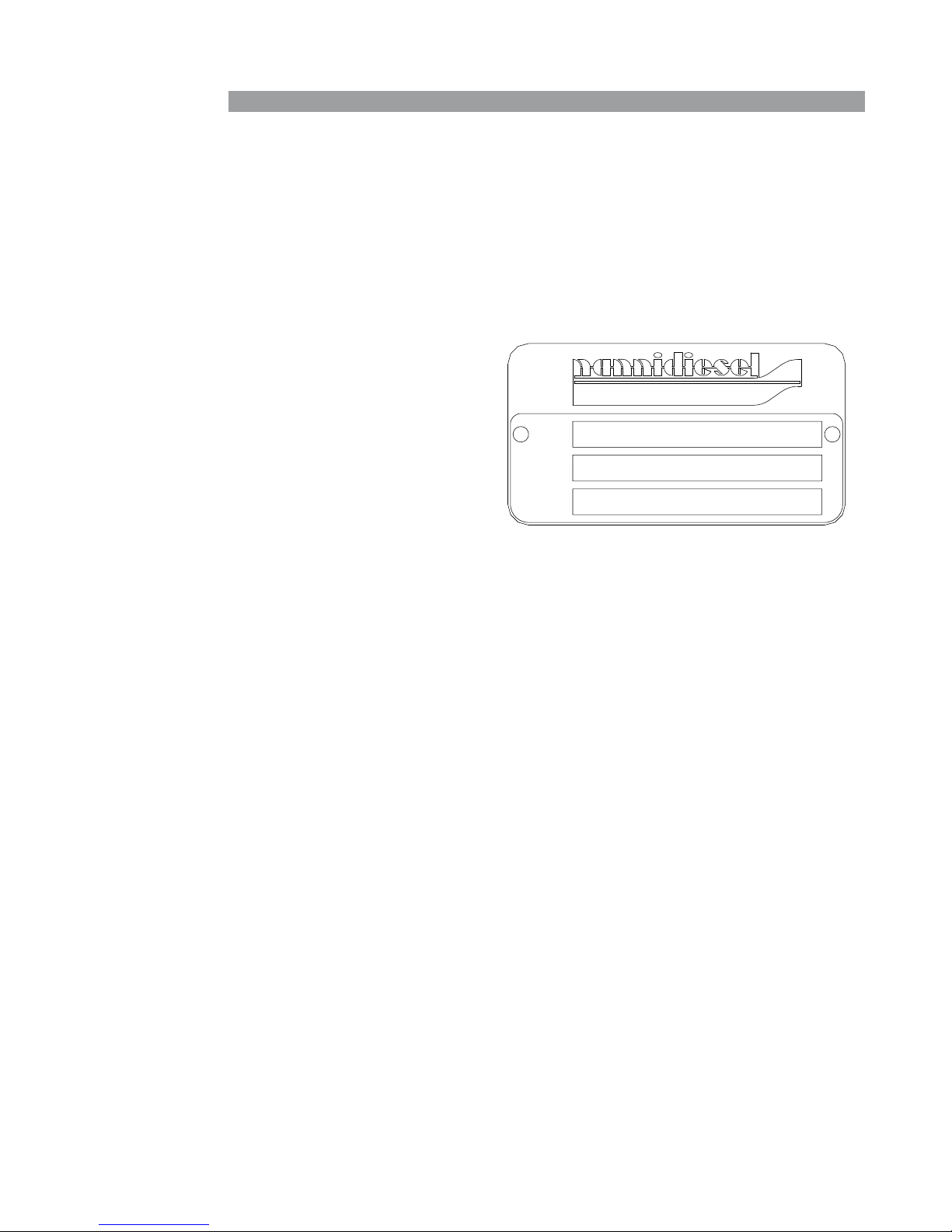
Identification plates
Your propulsion system has at least 2 identification plates:
one for the engine and one for the gearbox.
Keep these plates accessible and in good condition.
Record and keep the engine and gearbox serial number
and designation. These numbers will be useful if you work
on your engine, order parts or invoke the warranty.
The engine identification plate is as follows:
The TYP inscription indicates the commercial designation
of the engine (eg. V6.350).
The NR inscription indicates the engine serial number.
The CODE inscription lists the various specifications of
your engine.
Additional equipment
Y our engine can be fitted with optional pieces of equipment
(alternators, intercalated generator, hybrid propulsion,
pumps, trolling valve, etc.)
Refer to the additional documentation concerning this
equipment or contact your authorised Nanni Diesel dealer
for more information.
6
TYP
NR
CODE

Warranty
The owner of the engine is responsible for all safety
and maintenance checks as well as for following the
maintenance instructions as set forth in this manual and
on the Silverwake warranty booklet. The performance and
reliability of your engine depend on you following these
instructions.
Maintenance should be entrusted to a specialist authorised
by Nanni Diesel. The validity of the warranty is dependent
on maintenance operations being carried out by an
authorised representative.
Wear and tear on parts as well as maintenance costs
arise from normal use of the engine and therefore do not
constitute manufacturing or material faults under the terms
of the warranty.
We strongly advise against making any changes to
the engine’s settings, as well as any other technical
modification (accessories, spare parts, hitched equipment
etc.) not authorised by Nanni Diesel.
Any modification will cause the warranty to be cancelled as
we cannot be held liable for work carried out beyond our
control.
Environmental responsibility
Nanni Diesel designs its engines to have minimum
environmental impact and a maximum service life. This
objective, however, can only be achieved with your full
cooperation. Our operating and maintenance instructions
are to help you to protect your engine and adopt responsible
behaviour vis-à-vis the environment.
Ensure you only use the fuels and oils recommended in this
manual. Using another type of fuel or oil could cause major
generator malfunctions: higher consumption, reduced
engine service life, greater discharge of exhaust gases.
When draining the oil and changing the oil or fuel filter,
dispose of the waste in the appropriate container. These
fluids cause major damage to flora and fauna if discharged
into nature. Ask the pump attendant for an absorption kit
in the event of accidental discharge of oil or fuel into the
water.
The different fluids used to run the engine are a health
hazard. Carefully read the instructions on the packaging of
these products and always check that the ventilation in the
storage compartment is adequate.
Preparations before starting :
When the engine has been installed on board and before
removing the protective elements covering the different
orifices, clean the exterior surface of the propulsion system.
For transportation reasons, some of our engines are
delivered without their operating fluids. In all cases, you
must:
• Check the levels and fill the engine oil if necessary.
• Fill the exchanger with coolant and degas if necessary.
• Check the belt tension.
• Check the tightness of the different connections and
drain caps (coolant and oil).
• Check the tightness of the alternator electrical lugs
(check the cabling by referring to the corresponding
documentation), battery terminals, circuit breaker,
connection of extension sections, battery electrolyte
level.
• Make a final check of the fixing elements and a visual
check of the engine as a whole.
• Check the operation of the ventilation system.
Some of these operations are explained in more detail later
in this manual.
I Attention! : The modern diesel engine is precision
equipment that requires the use of a high-quality fuel and
lubricant.
Fuel supply
Ensure that the fuel contains no residues. If it does, use
special filters.
Avoid using fuel mixed with water or other substances as
you may damage the engine.
The engine performance is influenced by the fuel
temperature, the temperature and relative humidity of the
exhaust air and by the altitude.
Behaviour of the boat
The weight distribution on board can modify the centre of
gravity of the boat and have an impact on its behaviour in
navigation.
The condition of the hull is also a critical factor. A dirty and /
or damaged hull will modify the behaviour of the boat.
The propeller must be adapted to the boat and the use that
is made of it. A faulty operation of the boat is often due
to an inadequate and / or damaged propeller.
7
Presentation
STOP
ON / STOP START
RPM x 100
10
0
40
30
20
5
35
15
25
bar
0
2
4
6
8
10
0
40
80
120
160
psi
!
°C
40
60
80
100
120
°F
105
180
220
250
!
!
Presentation
8
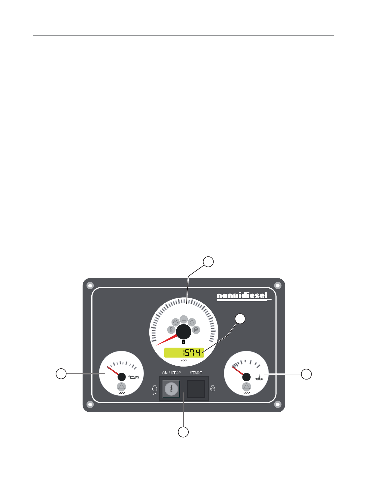
Instrument panel
The instrument panel provides you with important
information about the engine when it is operational. Check
this information regularly when the engine is operational.
The position or appearance of the instruments represented
here may vary depending on the type of instrument panel.
Not all instrument panels have all these elements.
If your instrument panel does not match the models
described in this chapter, contact your Nanni Diesel
authorised dealer.
1. Revolution counter. Indicates the rotation speed of
the engine in rpm. When the ignition is on, indicates the
voltage at the battery terminals.
2. Hour meter/Voltmeter. Record the functioning hours of
the engine. When the ignition is on, indicates the voltage at
the battery terminals.
3. Engine oil pressure. Attention! This indicator does
not show the engine oil level. This indicator shows the oil
pressure. The pilot lamp inside the dial is lit and an audible
alarm sounds if the oil pressure in the lubrication circuit
falls. At idle , the pressure is generally lower.
I Danger! : If this alarm goes off, stop the engine - except
in cases of extreme urgency - and contact an authorised
Nanni Diesel dealer.
4. Coolant temperature. Indicates the coolant temperature.
The pilot lamp inside the dial is lit and an audible alarm
sounds if the coolant in the cooling circuit overheats.
In normal operation, the temperature must be between 75
and 85° Celsius.
I Danger! : If this alarm goes off, let the engine run at
idle few minutes and check that the seawater flows
through the exhaust outlet. If the water does not flow or if
the temperature does not drop, stop the engine - except
in cases of extreme urgency - and contact an authorised
Nanni Diesel dealer.
5. Sta rtin g switch/ key This component star ts and stops
the engine. The ON/STOP key switch powers up and stops
the engine. The START button starts it.
Certain panels (“button” panels) may not be equipped with
a starter key. The ON/STOP button switches on the engine.
1
2
4
3
5
!
9
Presentation
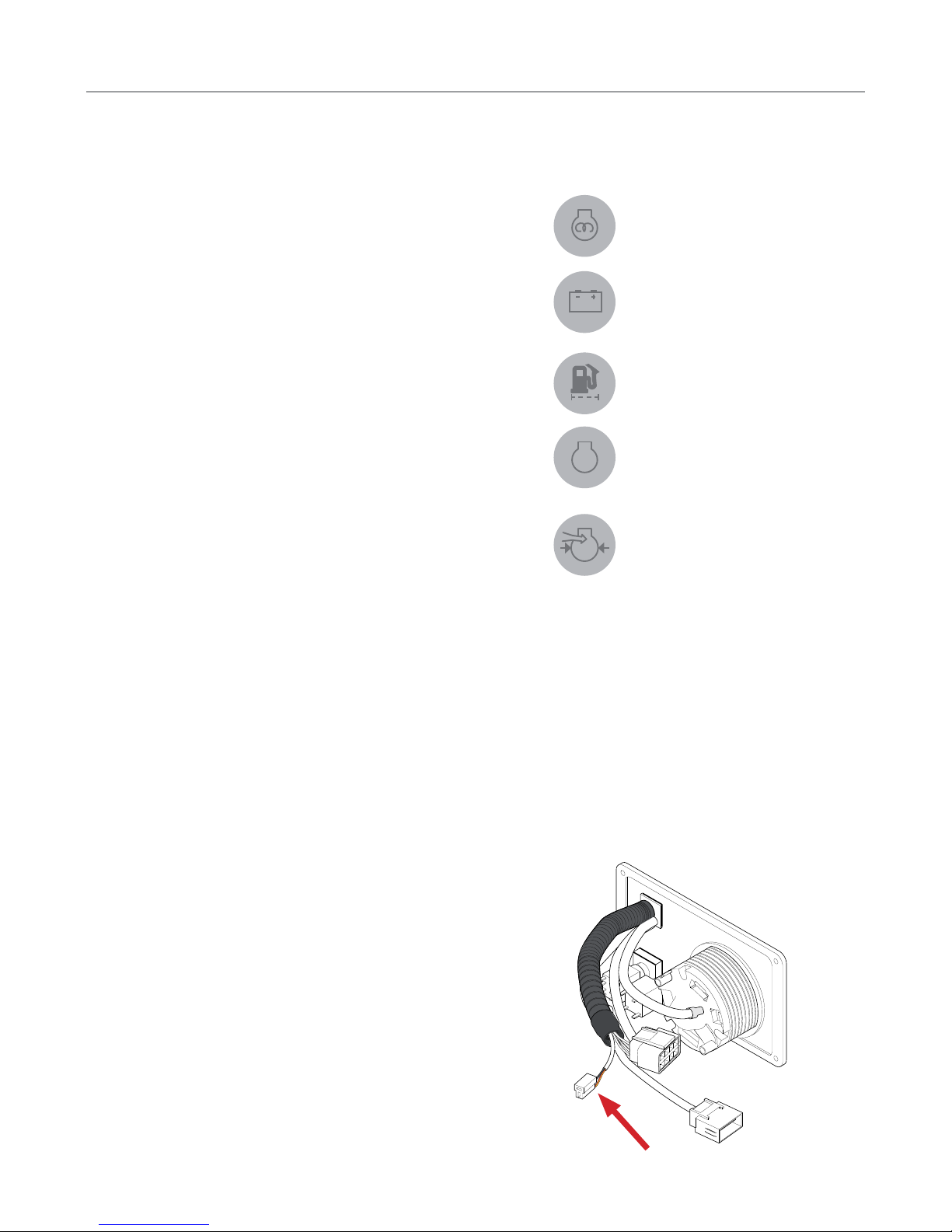
Warning lights & alarms
6. Heating . This indicator is lit when the glow plugs are heating
the combustion chambers (if fi tted on your engine).
7. Battery charge. This indicator is lit when the engine is switched
on (ignition). If it lights when the engine is running, this indicates
an engine alternator charging fault.
8. Water in fuel fi lter (if fi tted). This indicator is lit when there is
too much water in the fuel fi lter.
9. Faulty system. This indicator is lit when there is a failure on
the electronic system of the engine. If this indicator lights, contact
an authorised Nanni Diesel dealer.
10. High p ressure t urbo. This aler t indicator indicates t hat the
air pressure in the turbocharger is too high.
If one or more of these lights come on when the engine is
running, stop the engine (except in emergencies) and contact an
authorized dealer.
Throttle lever
On the majority of boats, the engine throttle includes the speed
control and gear changing functions (forward / reverse).
However, some boats may be fitted with a reverse command or a
safety mechanism that prevents the engine from being started if
the throttle is not in the neutral position.
Get information from the boat builder about the type of throttle
operation.
Auxiliary 12V output on instruments panel
The A4, B4 and C4 panels are equipped with an auxiliary output
of 12V / 3A.
The interfaces linking the panels to the engine are fi tted with a
fuse.
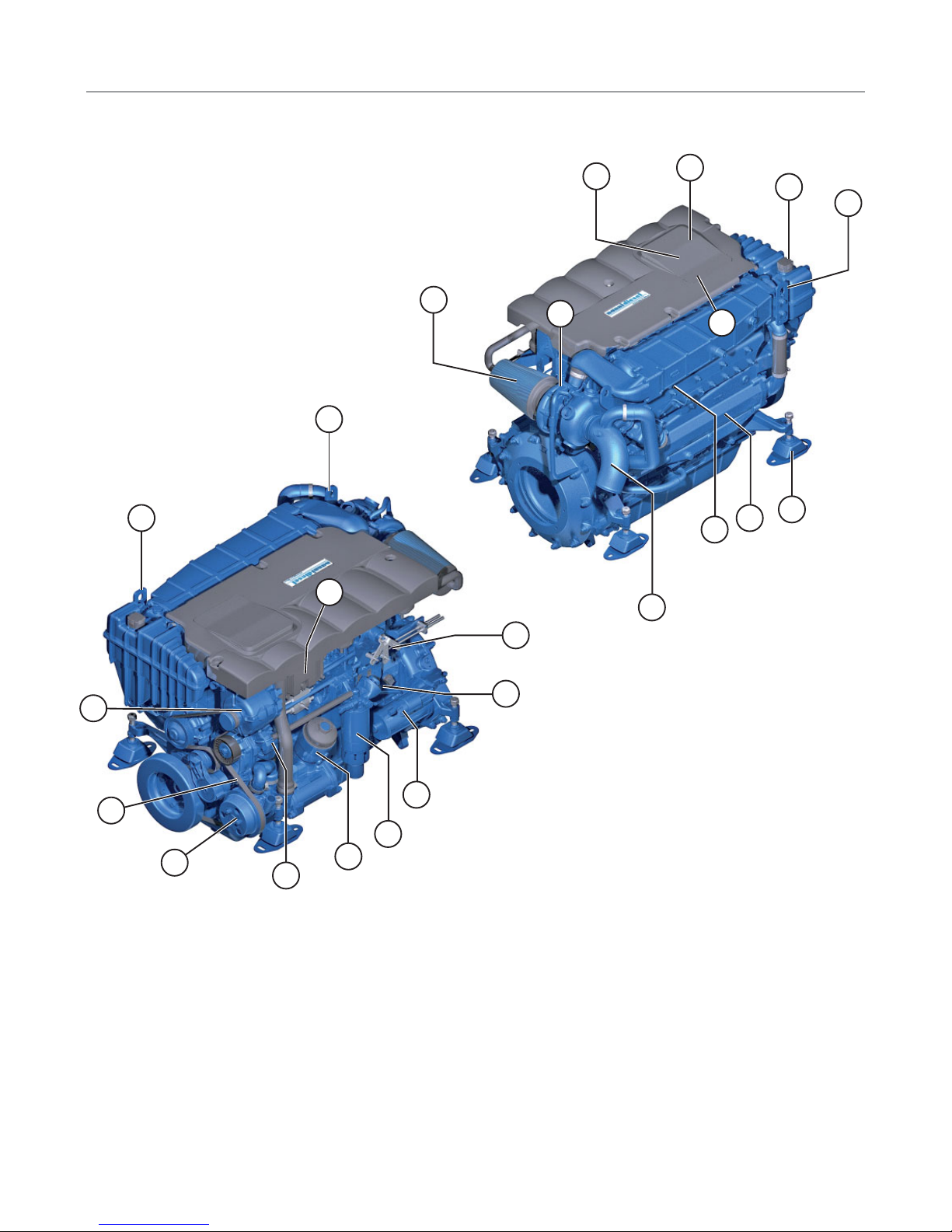
1. Engine alternator
2. Engine alternator belt
3. Starter
4. Air filter
5. High pressure injection fuel pump
6. Throttle lever
7. Fuel filter
8. Exhust elbow
9. Fuel fill orifice
10. Oil drain orifice
11. Oil gauge
12. Oil filter
13. Heat exchanger
14. Coolant fill orifice
15. Seawater pump
16. Heat exchanger drain plug
17. Electronic control unit
18. Supports
19. Turbocompressor
20. Hoisting eyes
21. Fuses
Presentation
10
Principal parts of the engine
Certain equipment may not be part of your engine
20
14
20
10
9
18
13
16
8
4
19
20
20
15
6
21
3
7
12
5
17
2
1
 Loading...