

Page 1

Instruction manual
Marine Diesel engines
H4.115
H4.130
H4.150
H4.170
970315364
01032011-F
Page 2

Contents
Safety precautions ..................................................................................................................3
Presentation ............................................................................................................................6
Identification plates ...................................................................................................................... 6
Additional equipment ................................................................................................................... 6
Warranty ...................................................................................................................................... 7
Environmental responsibility ........................................................................................................ 7
Preparations before starting........................................................................................................ 7
Fuel supply................................................................................................................................... 7
Behaviour of the boat ................................................................................................................... 7
Instrument panel .....................................................................................................................8
Warning lights & alarms ............................................................................................................... 9
Throttle lever ................................................................................................................................ 9
Principal parts of the engine .................................................................................................10
Installation inspection ...........................................................................................................11
Operation of the engine ........................................................................................................12
Before starting ................................................................................................................12
Starting the engine ..........................................................................................................12
During operation ...................................................................................................................13
Forward / reverse speed ............................................................................................................ 13
Running in .................................................................................................................................. 13
Stopping the engine .............................................................................................................13
Emergency stop ..............................................................................................................13
After the engine has stopped ..........................................................................................13
Maintenance ..........................................................................................................................14
Daily checks .........................................................................................................................15
Fuel system ..........................................................................................................................16
Bleeding the fuel circuit ...................................................................................................16
Replacing the fuel fi lter ....................................................................................................16
Replacing the fuel prefi lter ...............................................................................................17
Draining the water from the fuel prefi lter .........................................................................17
Lubrication circuit .................................................................................................................18
Checking the oil level ......................................................................................................18
Replacing the oil fi lter cartridge .......................................................................................18
Draining the engine oil .....................................................................................................19
Cooling circuit - coolant ........................................................................................................20
Coolant fi lling ...................................................................................................................21
Draining the cooling circuit ..............................................................................................21
Rinsing the cooling circuit ................................................................................................21
Cooling circuit - seawater .....................................................................................................22
Cleaning the seawater fi lter .............................................................................................22
Draining the seawater circuit ...........................................................................................22
Replacing the seawater pump rotor ................................................................................23
Air fi lter .................................................................................................................................24
Engine electrical system .......................................................................................................25
Check the electrolyte level ..............................................................................................25
Changing fuses ...............................................................................................................25
Protection against corrosion - Zinc anode ............................................................................26
Protecting the engine during periods of inactivity .................................................................27
Restarting the engine ...........................................................................................................27
Fault-finding ..........................................................................................................................28
Technical specifications ......................................................................................................30
2
Page 3

Locating or checking the coolant level.
Indicates that it is essential to read the instructions carefully before handling the engine.
Locating the electrical hazards.
Locating the hot parts entailing substantial risks of burns.
This icon indicates a risk of fi re.
Stipulates that you are strongly recommended against smoking and producing fl ames or sparks in the vicinity.
Locating an area containing pressurised fl uids.
Locating the hazardous rotating parts.
Locating the de-aeration orifi ce(s) (air bleed)
Locating or checking the engine oil level.
Locating the coolant drain orifi ce.
Locating the oil tank drain orifi ce.
Safety precautions
Read this chapter carefully as it concerns your safety. Most
accidents are caused by failing to follow basic safety rules.
Be aware of the possible risks involved in handling your
engine and make sure you take the necessary precautions
to protect yourself, those around you and your equipment.
This manual contains important safety indications and
information.
They are as follows:
I Danger! : This symbol indicates the risk of accidents
and serious personal injury, substantial property damage
or serious mechanical faults if the instructions are not
followed.
I Attention! : Indicates a risk of personal injury and/or
property damage when handling a component.
Remark: Indicates that important information must be
known in order to facilitate handling or in particular cases.
Using and handling an engine entails risks that could
prove to be extremely dangerous. Some work requires
specifi c knowledge and equipment. This work should be
carried out by Nanni Diesel authorised personnel or by a
professional. If you have to work on the engine, carefully
follow the safety instructions set down in this manual.
Certain information is displayed directly on the engine in the form of icons. This information helps you to quickly identify
the location of certain components and avoid possible hazards when working on the engine.
Ensure these indications are always visible and replace them if necessary.
3
Page 4

I Exhaust gas
Exhaust gases contain carbon monoxide. This colourless
and odourless gas is extremely harmful and could lead to
poisoning which could result in loss of consciousness or
death. The fi rst symptoms of carbon monoxide intoxication
are as follows:
• Dizziness
• Nausea
• Headache
• Throbbing temples
• Vomiting
• Fatigue and falling asleep
• Tense muscles
If you or anyone else in the vicinity of the engine experiences
any of these symptoms, leave the area of operation of the
engine and fi nd fresh air. If the symptoms persist, consult a
doctor and have your engine checked.
I Risk of electric shock
Never touch the electrical connectors when the engine is
operational. The voltage at the connector terminals can be
lethal.
Do not work on the engine without protection: protective
goggles and gloves, insulating blankets etc.
Always disconnect the engine and cut the current before
working on the electrical system. Isolate the shore power
supply to all the electrical circuit equipment.
Ensure your clothing and skin is not damp or sweaty when
handling electrical equipment. Remove watches, bracelets
and jewellery when working on electrical equipment.
Handling a capacitor that is still charged can be dangerous
and cause electrocution.
I Risk of burns
Never touch the hot parts of the engine or the exhaust
circuit.
An operational engine gets very hot: the exhaust elbow and
pipe, turbocompressor, starter, oil sump, oil, coolant in the
hoses and pipes are hot and can burn.
Always check the coolant level before starting the engine.
Fluids ejected under pressure can cause serious injury.
Release all the pressure in the circuits before removing the
caps.
Never open the coolant and oil circuit caps when the engine
is operational and/or hot.
Never start or run the engine when the oil fi ll cap is not
screwed on as hot oil could spray out.
If you come into contact with any of these fl uids, consult a
doctor immediately.
If the engine gets too hot, switch it off and disconnect it and
wait for it to cool down before handling.
I Risk of fi re
Do not smoke near the engine and keep it away from
sources of ignition (fl ames or sparks) or any other potential
fl ammable vapour or liquid sources.
Do not run the engine without an air fi lter.
Do not run the engine in an area in which fl ammable or
explosive materials are stored or where gas is present.
Ensure there are no fl ammable liquids in the engine
compartment.
Immediately clean up any liquids spilled over yourself or
the fl oor and keep the engine compartment clean and
accessible so as to minimise the risk of fi re. Be careful as
fuel can burn.
I Risk of explosion
Explosions caused by fuel vapour can cause serious injury!
Carefully follow the safety rules when fi lling the fuel.
Open and ventilate the storage area of the engine after
fi lling. Check that there are no fuel vapours or leaks before
starting the fan (if fi tted). Switch the fan on for 5 minutes
before starting the engine.
All fuel vapours are fl ammable and explosive. Be careful
when handling and storing fuel. Store the fuel in a ventilated
area away from sources of ignition (sparks or fl ames) and
out of the reach of children.
Stop the engine before fi lling with fuel or lubricant. Do not
smoke near the engine and keep it away from sources of
ignition (fl ames) when fi lling with fuel and/or lubricant. Wear
gloves when investigating possible leaks.
Do not alter or damage the fuel circuit. Close the fuel circuit
whenever you work on it.
Ensure you always have an appropriate working extinguisher
to hand.
Safety precautions
4
Page 5

I Accidental starting
Accidental starting can cause serious injury and even death!
Disconnect the battery before working on the engine.
Ensure no one is alongside the engine or working on the
gearbox, the shaft line and / or the propeller before starting
it.
Ensure all the protection mechanisms are in place before
starting the engine.
I Risk of battery explosion
A battery explosion can cause serious injury and even
death!
Do not smoke near the batteries and keep them away
from sources of ignition (fl ames or sparks). They produce
hydrogen which could ignite or explode on contact with an
electrical arc or a fl ame. Switch off all electrical appliances
in the vicinity when you are working on the batteries. Ensure
the battery storage compartment is corrected ventilated.
Avoid touching the battery terminals with metal tools so
that no sparks are created which could cause an explosion.
Remove your rings, bracelets and necklaces before handing
the batteries.
I Battery acid
The acid in batteries can cause serious injury and even
death!
When servicing the batteries, wear protective gloves and
goggles. Batteries contain sulphuric acid which is highly
corrosive.
Acid can spurt from batteries when they are handled. If the
acid comes into contact with the skin, rinse thoroughly in
fresh water and consult a doctor.
I Exhaust gas
Ensure the exhaust circuit correctly expels the gas produced
by the engine.
Regularly check that the exhaust circuit is free of leaks and
that the exhaust elbow is correctly affi xed.
Operate the engine in a well aerated and ventilated area
away from other people. Run the fan when the engine is
operational.
I Rotating parts
Rotating parts can be extremely dangerous and cause
serious injury and even death!
Do not work on the engine when it is operational. If work
on the engine when running is absolutely necessary, do not
touch any hot or rotating parts.
Baggy clothing, hair or objects could be pulled in and/or
caught and cause serious injury or substantial property
damage.
Do not wear bracelets, necklaces or rings when working on
the engine.
Check that the bolts and screws are properly tightened and
that the protection mechanisms are in place.
Do not check the fl uid levels or tension of the alternator belt
when the engine is operational.
I Lifting the engine
To lift the engine, use the hoisting eyes on the appliance.
Always check the robustness and overall condition of
the lifting equipment. Use suitable gear (cables, beams,
machines, etc.) to lift your engine. Check that your gear
is capable of lifting the engine all the equipment that are
mounted on the engine.
Lifting cables and chains must be able to move parallel to
each other.
Do not forget that any additional equipment mounted on
the engine could alter its centre of gravity. When lifting
the engine, it should remain as parallel as possible to the
ground.
I Maintenance and spare parts
Nanni Diesel engines are designed to meet the different
emission standards while delivering maximum service life
and reliability.
Regularly servicing and replacing parts with original Nanni
Diesel parts will ensure the engine continues to function
optimally.
These parts can be ordered from all Nanni Diesel dealers
throughout the world.
I Chemical products
The different fl uids used to run the engine are a health
hazard.
Carefully read the instructions on the packaging of these
products and always check that the ventilation in the hold
space is adequate.
5
Safety precautions
Page 6

Presentation
Thank you for choosing a Nanni Diesel engine!
Contact a Nanni Diesel authorised dealer for the servicing
of your equipment. A list of dealers can be found on our
web site:
www.nannidiesel.com
Nanni Diesel engines are the product of many years of
experience in the development of marine engines and
equipment designed for use in open seas.
These instructions concern the engines
H4.115
H4.130
H4.150
H4.170
These engines have been developed using the very latest
innovations in the diesel engine fi eld. Their main features
are common rail direct fuel injection, 4 valves per cylinder,
a turbocharger and 2 balance shafts.
The injection system is controlled by an electronic control
unit (ECU). This unit regulates the amount of diesel injected
according to different parameters.
These engines have also been equipped with fuses on
the electrical circuit which will trip in the event of overload
current or a short circuit, in order to avoid damage to the
parts.
Before using, ensure you have the correct manual for your
engine. We will explain how to identify your equipment and
its principal specifi cations in the chapters to follow. If you
don’t have the correct manual, please contact your Nanni
Diesel authorised dealer.
Carefully read all of this engine instruction manual and the
gearbox documentation before starting the engine.
Pay particular attention to the information on personal
safety. This manual must always be to hand where the
engine is used.
We recommend that you visually check the overall condition
of your engine before and after using it each time so that
you familiarise yourself with the different components and
can more easily detect any fuel, oil or coolant leaks or
abnormal wearing of the principal parts.
All the information and specifi cations in this manual are
based on the technical data applicable at the time of its
publication. Changes and updates may be made by Nanni
Diesel without notice.
Certain images, diagrams or equipment described in this
manual may not exactly represent (or be part of) your
engine order.
Identification plates
Your propulsion system has at least 2 identification plates:
one for the engine and one for the gearbox.
Keep these plates accessible and in good condition.
Record and keep the engine and gearbox serial number
and designation. These numbers will be useful if you work
on your engine, order parts or invoke the warranty.
The engine identification plate is as follows:
The TYP inscription indicates the commercial designation
of the engine (eg. H4.150).
The NR inscription indicates the engine serial number.
The CODE inscription lists the various specifications of
your engine.
Additional equipment
Your engine can be fitted with optional pieces of equipment
(alternators, intercalated generator, hybrid propulsion,
pumps, trolling valve, etc.)
Refer to the additional documentation concerning this
equipment or contact your authorised Nanni Diesel dealer
for more information.
6
TYP
NR
CODE
Page 7

Warranty
The owner of the engine is responsible for all safety
and maintenance checks as well as for following the
maintenance instructions as set forth in this manual and
on the Silverwake warranty booklet. The performance and
reliability of your engine depend on you following these
instructions.
Maintenance should be entrusted to a specialist authorised
by Nanni Diesel. The validity of the warranty is dependent
on maintenance operations being carried out by an
authorised representative.
Wear and tear on parts as well as maintenance costs
arise from normal use of the engine and therefore do not
constitute manufacturing or material faults under the terms
of the warranty.
We strongly advise against making any changes to
the engine’s settings, as well as any other technical
modification (accessories, spare parts, hitched equipment
etc.) not authorised by Nanni Diesel.
Any modification will cause the warranty to be cancelled as
we cannot be held liable for work carried out beyond our
control.
Environmental responsibility
Nanni Diesel designs its engines to have minimum
environmental impact and a maximum service life. This
objective, however, can only be achieved with your full
cooperation. Our operating and maintenance instructions
are to help you to protect your engine and adopt responsible
behaviour vis-à-vis the environment.
Ensure you only use the fuels and oils recommended in this
manual. Using another type of fuel or oil could cause major
generator malfunctions: higher consumption, reduced
engine service life, greater discharge of exhaust gases.
When draining the oil and changing the oil or fuel filter,
dispose of the waste in the appropriate container. These
fluids cause major damage to flora and fauna if discharged
into nature. Ask the pump attendant for an absorption kit
in the event of accidental discharge of oil or fuel into the
water.
The different fluids used to run the engine are a health
hazard. Carefully read the instructions on the packaging of
these products and always check that the ventilation in the
storage compartment is adequate.
Preparations before starting :
When the engine has been installed on board and before
removing the protective elements covering the different
orifices, clean the exterior surface of the propulsion system.
For transportation reasons, some of our engines are
delivered without their operating fluids. In all cases, you
must:
• Check the levels and fill the engine oil if necessary.
• Fill the exchanger with coolant and degas if necessary.
• Check the belt tension.
• Check the tightness of the different connections and
drain caps (coolant and oil).
• Check the tightness of the alternator electrical lugs
(check the cabling by referring to the corresponding
documentation), battery terminals, circuit breaker,
connection of extension sections, battery electrolyte
level.
• Make a final check of the fixing elements and a visual
check of the engine as a whole.
• Check the operation of the ventilation system.
Some of these operations are explained in more detail later
in this manual.
I Attention! : The modern diesel engine is precision
equipment that requires the use of a high-quality fuel and
lubricant.
Fuel supply
Ensure that the fuel contains no residues. If it does, use
special filters.
Avoid using fuel mixed with water or other substances as
you may damage the engine.
The engine performance is influenced by the fuel
temperature, the temperature and relative humidity of the
exhaust air and by the altitude.
Behaviour of the boat
The weight distribution on board can modify the centre of
gravity of the boat and have an impact on its behaviour in
navigation.
The condition of the hull is also a critical factor. A dirty and /
or damaged hull will modify the behaviour of the boat.
The propeller must be adapted to the boat and the use that
is made of it. A faulty operation of the boat is often due
to an inadequate and / or damaged propeller.
7
Presentation
Page 8

STOP
ON / STOP START
RPM x 100
10
0
40
30
20
5
35
15
25
bar
0
2
4
6
8
10
0
40
80
120
160
psi
!
°C
40
60
80
100
120
°F
105
180
220
250
!
!
Presentation
8
Instrument panel
The instrument panel provides you with important
information about the engine when it is operational. Check
this information regularly when the engine is operational.
The position or appearance of the instruments represented
here may vary depending on the type of instrument panel.
Not all instrument panels have all these elements.
If your instrument panel does not match the models
described in this chapter, contact your Nanni Diesel
authorised dealer.
1. Revolution counter. Indicates the rotation speed of
the engine in rpm. When the ignition is on, indicates the
voltage at the battery terminals.
2. Hour meter/Voltmeter. Record the functioning hours of
the engine. When the ignition is on, indicates the voltage at
the battery terminals.
3. Engine oil pressure. Attention! This indicator does
not show the engine oil level. This indicator shows the oil
pressure. The pilot lamp inside the dial is lit and an audible
alarm sounds if the oil pressure in the lubrication circuit
falls. At idle , the pressure is generally lower.
I Danger! : If this alarm goes off, stop the engine - except
in cases of extreme urgency - and contact an authorised
Nanni Diesel dealer.
4. Coolant temperature. Indicates the coolant temperature.
The pilot lamp inside the dial is lit and an audible alarm
sounds if the coolant in the cooling circuit overheats.
In normal operation, the temperature must be between 75
and 85° Celsius.
I Danger! : If this alarm goes off, let the engine run at
idle few minutes and check that the seawater flows
through the exhaust outlet. If the water does not flow or if
the temperature does not drop, stop the engine - except
in cases of extreme urgency - and contact an authorised
Nanni Diesel dealer.
5. Starting switch/key This component starts and stops
the engine. The ON/STOP key switch powers up and stops
the engine. The START button starts it.
Certain panels (“button” panels) may not be equipped with
a starter key. The ON/STOP button switches on the engine.
1
2
4
3
5
Page 9

!
9
Presentation
Warning lights & alarms
6. Heating. This indicator is lit when the glow plugs are heating
the combustion chambers (if fi tted on your engine).
7. Battery charge. This indicator is lit when the engine is switched
on (ignition). If it lights when the engine is running, this indicates
an engine alternator charging fault.
8. Water in fuel fi lter (if fi tted). This indicator is lit when there is
too much water in the fuel fi lter.
9. Faulty system. This indicator is lit when there is a failure on
the electronic system of the engine. If this indicator lights, contact
an authorised Nanni Diesel dealer.
10. High pressure turbo. This alert indicator indicates that the
air pressure in the turbocharger is too high.
If one or more of these lights come on when the engine is
running, stop the engine (except in emergencies) and contact an
authorized dealer.
Throttle lever
On the majority of boats, the engine throttle includes the speed
control and gear changing functions (forward / reverse).
However, some boats may be fitted with a reverse command or a
safety mechanism that prevents the engine from being started if
the throttle is not in the neutral position.
Get information from the boat builder about the type of throttle
operation.
Auxiliary 12V output on instruments panel
The A4, B4 and C4 panels are equipped with an auxiliary output
of 12V / 3A.
The interfaces linking the panels to the engine are fi tted with a
fuse.
Page 10

1. Engine alternator
2. Engine alternator belt
3. Starter
4. Air filter
5. High pressure injection fuel pump
6. Throttle lever
7. Fuel filter
8. Exhust elbow
9. Fuel fill orifice
10. Oil drain orifice
11. Oil gauge
12. Oil filter
13. Heat exchanger
14. Coolant fill orifice
15. Seawater pump
16. Heat exchanger drain plug
17. Electronic control unit
18. Supports
19. Turbocompressor
20. Hoisting eyes
21. Fuses
Presentation
10
Principal parts of the engine
Certain equipment may not be part of your engine
8
4
15
7
12
5
1
2
3
9
10
11
14
13
16
17
18
18
18
19
20
20
21
Page 11

4
3
5
6
2
1
7
11
Presentation
Installation inspection
I Attention! : Your engine must be installed by an authorised shipyard or a qualifi ed Nanni Industries representative in
accordance with the on board assembly instructions. However, you can check some important points on the installation
of the engine.
1. Engine frame
The engine frame must be solid and able to absorb all the
dynamic stress as well as the weight of the engine. It must
be connected to the hull by an area as large as possible.
The engine must not be at an angle of more than 15° when
the boat is stopped.
2. Propeller shaft
The choice of propulsion system must be made according
to the restrictions arising from the engine, the boat, and the
use of the boat.
3. Waterlock exhaust box
The waterlock must be positioned as close to the engine
and as low as possible.
4. Hull outlet
The hull outlet must be located 15cm below the water line.
The tube between the exhaust box and the hull outlet must
form a swan-neck shape to avoid any water getting into the
exhaust system through the hull outlet.
5. Anti-siphon valve
Mandatory on boats whose engine is below the waterline.
The anti-siphon valve must be installed at the end of the
seawater system before injection in the exhaust elbow and
must be positioned above the waterline, between 0.5 and
2 metres.
6. Seawater filter
This must always be positioned at least 15 cm above the
waterline.
7. Through-hull valve
On yachts and boats that do not go above 12 knots, the
water inlet must be turned towards the end of the boat.
On motor boats that go over 12 knots, the water inlet must
be turned forwards the end of the boat.
Engine room
The temperature inside the engine compartment must not
exceed 50°C with a maximum difference of 20°C with the
outside temperature.
Slow boats must have a ventilator fitted. Fresh air from the
front is circulated from front to back. The front air intake is
located low down at the front of the engine compartment
and the outlet high at the back for optimum air circulation.
Electrical installation
An incorrect or faulty electrical installation can cause
leakage currents that can affect the galvanic protection of
the engine and damage the engine subsequently.
The installer must ensure to take all necessary precautions
to protect the engine against corrosion.
Page 12

Operation of the engine
1212
Before starting
I Attention! : Before starting, ensure that the seawater
intake is open as the seawater pump rotor can be damaged if run dry for just a few seconds.
Never use a starting aerosol or any other equivalent product. These products are highly flammable.
Before turning the starter key and before the engine is
used each time:
• Open the hold space panel(s) to fully ventilate the hold
space if it is not equipped with a fan. Otherwise run the
fan in the hold space for 5 minutes.
• Check the fuel level .
• Check that the throttle is in the correct neutral position.
• Open the fuel supply valve and prime the system if
necessary
• Open the seawater intake valve (if fitted)
• Check there are no fuel, oil or coolant leaks
• Check the engine oil level and fill with the recommend-
ed oil if necessary. See the “Maintenance” section for
more information.
• Check the coolant level and fill with the recommended
coolant if necessary. See the “Maintenance” section
for more information.
I Attention! : Ensure you have refitted the protection ele-
ments before starting the engine.
• Close the battery switch (ON position)
Remark : If your engine has not been used for several
months of if the fuel circuit has been drained, use the priming pump situated above the fuel filter. This fills the fuel
circuit if it has drained out or after a circuit component has
been replaced.
I Danger! : The propeller can cause serious injury when
it is moving, ensure that no-one is near the propeller before
starting the engine and never sail near swimmers.
Starting the engine
Remark : When starting the engine for the first time, let it
run at idle for several minutes.
If the engine is not used regularly, turn the ignition and let
the engine run at idle until it reaches operating temperature. Do this at least one time per month when not in use.
Carry out the following operations to start your engine in
complete safety:
1. Put the throttle in the neutral position
2. Put the key into the ON/STOP starting/switch
3. Turn the key a quarter-turn to the right. All of the in-
dicators will light and an audible signal will sound. This
stage allows you to check that these elements are working properly. After a few seconds, only the oil and battery
charge indicators will remain lit.
4. Depress the START button to the midpoint to begin
heating and keep it depressed for 5 to 20 seconds depending on the ambient temperature. Depress the button
fully to start the engine.
Button panel
For button panels (with no starter key):
1. Press the ON/STOP button. All of the indicators will
light and an audible signal will sound. This stage allows
you to check that these elements are working properly.
After a few moments, only the oil and battery charge indicators will remain lit.
2. Depress the START button to the midpoint to begin
heating and keep it depressed for 5 to 20 seconds depending on the ambient temperature. Depress the button
fully to start the engine.
I Attention! : Never press the START button when the
engine is running.
Remark : Consult your authorised Nanni Diesel dealer
about the precautions to take when using the engine in a
cold environment.
I Attention! : If the engine does not start on the first at-
tempt, repeat the manoeuvre, waiting 5 to 15 seconds between each attempt, with the engine switched off. Never
force it as there is a risk of water backflow into the engine
via the exhaust system.
Let the engine warm up at idle few minutes before reaching
your cruising speed.
Page 13

13
Operation of the engine
During operation
RPM speed of the engine
Refer to the chapter «Technical specifications» for informations about the rated rpm speed of your engine.
Do not operate the engine at a too low rpm speed for a
long period as it could lead to increased oil consumption
among other things. At a low speed, the fuel combustion is
not complete and deposits may form in the engine and in
its exhaust system. Run the engine at full throttle for 4 to 5
hours per year in order to burn off any possible deposits.
Cruising spee d
Set your cruising speed to 200 rpm below the maximum
speed at full throttle for the best sailing conditions.
Forward / reverse speed
I Danger! : Never reverse the gear when the boat is at full
speed. Gear changes made at too high speed can damage
the engine and the transmission.
Carry out the following operations for forward / reverse
manoeuvres:
1. Lower the engine down to idling and wait for the boat
to lose as much speed as possible.
2. Bring the throttle to the neutral position and wait a few
seconds.
3. Push the control lever to the reverse direction and
change gear.
Running in
Operate your engine with care for the fi rst 50 hours of op-
eration.
Do not accelerate immediately after starting the engine
without giving the engine the time to warm up by idling for
several minutes and only run at full speed for short periods
of time.
Stopping the engine
Let the engine run at idle in the neutral position for few minutes before turning it off, particularly if the engine has been
running at high speeds and high throttle settings.
Turn the key counter-clockwise. The engine stops and all
the indicators will be extinguished.
For button panels, depress the ON/STOP button and then
release it.
Emergency stop
You can stop the engine manually if the standard shutdown procedure is not working or in an emergency by cutting the fuel supply.
I Danger! : Working on a running motor is extremely
dangerous.
After the engine has stopped
Open the circuit breaker (battery supply off), close the seawater intake valve (if fi tted) and the fuel feed valve. Check
the condition of the compartment in order to identify any
leaks.
I Danger! : Even after your engine has stopped, ele-
ments remain hot and pressurised for several minutes. As
far as possible, limit work on the engine immediately after
stopping it.
I Attention! : If the craft is being towed, stop the engine
and always close the seawater intake valve to prevent the
engine from accidentally fi lling with seawater.
TWIN-ENGINE BOATS: If sailing with a single engine,
close the seawater intake valve of the stopped engine. Do
not forget to open it again before restarting the engine.
Page 14

1414
The regular maintenance of your engine is essential for
ensuring optimal reliability and service life. The following
operations and the those described in the Silverwake
warranty booklet will enable you to extend the service life
of your engine and reduce its impact on the environment.
During the warranty period, it is essential that all work is
carried out by a Nanni Diesel authorised dealer. However,
some regular checks, particularly those made each time the
engine is used, can only be made by the owner.
Certain operations are explained to you further on so that
you can work on the engine in an emergency or if there
is no repair centre nearby. We recommend you have your
work checked by a Nanni Diesel authorised specialist.
I Attention! : As far as possible, limit work on the engine
when it is running and/or when you are sailing.
These instructions only describe a part of the maintenance
operations to be carried out. Find the complete list on the
Silverwake warranty booklet. The operations listed on the
Silverwake must be carried out by an authorised Nanni
Diesel technician.
The instrument panel shows you how long your engine has
run since its commissioning.
Remark: Certain equipment is optional and may not be part
of your engine.
In order to preserve the mechanical qualities of the engine
and prolong its service life, we recommend you follow the
instructions below:
Use a coolant made of 50% water and 50% antifreeze.
Use tap water for the mix: Water that is too hard will
produce limescale build-up and will reduce the cooling
system’s effectiveness. This could lead to a piston jamming.
If you do not use antifreeze and the outdoor temperature
is below zero degrees Celsius, make sure to empty the
cooling water after every use.
The closed cooling circuit must be protected against
corrosion. If this circuit malfunctions, this could reduce its
efficiency and the engine’s service life.
Do not run the starter for more than 15 seconds: The
continuous use of the starter for more than 15 seconds will
damage the system.
Choose a diesel fuel meeting standard DIN-EN
590. If using Biodiesel (according to UNI EN14214
specifications) this can be blended up to 5% with a
fuel available in Europe (according to the DIN EN 590
standard: a lower quality fuel will result in poor combustion,
which may cause starting problems and heavy smoke
emissions.
Draining the fuel tank: Remove the deposits in the fuel
regularly.
Use a good-quality lubricant: Poor-quality lubricating oil
will damage the engine in terms of the wear of the parts,
jamming, etc., or rather reduce its service life.
The recommended lubricant must have the following
properties :
Degree: SAE 10W - 40
Minimum specifications ACEA A3, B3 or API SL, CF
Maintenance
Page 15

15
Maintenance
Daily checks
Habitually and regularly check the condition of the engine and its
compartment before and after it is used: check for the presence
or not of fuel or oil leaks, the tightness of the different clamps and
bolts, the condition of the belts, hoses and the various electrical
cables, the wear of the zinc anode (if fitted), the battery electrolyte
level.
These relatively simple checks can help you to detect possible
faults before major work on your engine is required.
I Attention! : Do not let oil, fuel or grease deposits build up
around the engine as they may increase the risk of fire in the
engine compartment.
Check the operation of the different lamps and indicators situated
on the instrument panel.
Stuffi ng box
Regularly check the watertightness of your stuffi ng box (if
equipped). As this system is not absolutely tight, it is natural that
a slight amount of water passes through the stuffi ng box. Correct
operation is characterized by a drop-by-drop water intake. If too
much water comes in, contact your Nanni Diesel dealer.
Control cables
Inspect the cables and check that they are not shredded or loose.
Grease the connections.
Page 16

C
Maintenance
16
Fuel system
I
Danger! : Total cleanliness must be guaranteed when working on the fuel circuit. No impurities must enter the injection
pump and the injectors. Carry out each of these operations with the engine cold and stopped.
A
B
Bleeding the fuel circuit
The fuel circuit is self-priming but manual bleeding is required
after replacing the fi lter, after have running out of fuel or after
a work on the circuit if it has been emptied.
• Untighten the drain valve screw A on the engine fuel
fi lter support.
• Pump the priming pump by pressing the button B
repeatedly until bubble-free fuel comes out of the drain
valve screw.
• Tighten the drain valve screw and lock the hand pump B.
I Attention! : Avoid draining all the fuel in the fi lter when
bleeding. If you have, remove the fi lter and replenish with fuel
before replacing it and repeat the bleeding.
Replacing the fuel fi lter
This fi lter treats the water and impurities in the fuel before it
enters the injection circuit.
• Cut the fuel intake at the tank.
• Place a receptacle under the fi lter and then remove the
used fi lter C cartridge.
• Apply a thin layer of fuel over the seal surface of the new
fi lter cartridge before fi tting it.
• Tighten it by hand until the fi lter makes contact with the
fi lter head then tighten it by a half-turn.
• Untighten the drain valve screw to release the air. Open
the fuel valve again and drain the circuit.
• Start the engine and check the assembly is leak-tight.
I Attention! : Used fi lters must be disposed of in an
appropriate container.
Page 17

Maintenance
Fuel system
Replacing the fuel prefi lter
The fuel prefi lter is an optional component that purifi es the
diesel before it is injected in the engine. These instructions
are given as an example only.
• Close the fuel valve on the fuel tank.
• Place a pail under the fuel prefi lter. Remove the fi lter
tank A
• Drain and clean the fi lter tank.
• Replace the cartridge B and re-install the tank.
• Open the fuel valve. Drain the feed system then start
the engine to check the leak-tightness.
Draining the water from the fuel prefi lter
Before starting the engine each time, ensure there is no
water in the fuel prefi lter. If there is water, place a tray under
the fuel prefi lter and then drain the water and impurities
using the bottom cap/valve.
B
A
17
Page 18

B
A
Maintenance
18
Lubrication circuit
Checking the oil level
I Attention! : Carry out these operations with the engine
stopped. Hot oil and hot surfaces can burn.
If oil of a different brand or viscosity to the previous oil is
used, drain the old oil. Never mix two different types of oil.
Observe the recommended draining intervals.
The oil level should be within the range indicated on the oil
gauge. To check the oil level:
• Start the engine and let it run at idle for several minutes.
• Stop the engine and remove the starter key.
• Remove and wipe down the gauge rod.
• Re-insert it and then remove it.
• Check whether the oil level is between the two notches.
If the level is too low, add more oil until reaching the
specifi ed level.
Fill the oil via the fi ll orifi ce situated on the top of the engine.
Add the oil slowly and wait several minutes before checking
the level again. This allows the oil to run into the engine
crankcase.
I Attention ! : Do not fi ll the crankcase above the maximum
level indicated on the gauge.
Replacing the oil fi lter cartridge
• Place a pail under the fi lter.
• Remove the oil fi lter cover A with a key.
• Remove the oil fi lter cartridge inside its casing B.
• Clean the fi lter support in order to prevent impurities
from entering the engine.
• Apply a fi ne layer of oil over the rubber seal of the new
cartridge.
• Remove the fi lter cartridge
• Install new cartridge, tighten it with a torque of 25 Nm.
• After replacing the fi lter, check that the engine oil is not
leaking through the seal and check the oil level using the
gauge. Add oil if necessary.
max
min
Page 19

A
Maintenance
Lubrication circuit
Draining the engine oil
I Attention! : Carry out these operations with the engine
stopped. Hot oil and hot surfaces can burn.
The oil is drained via the drain orifi ce using the drain pump,
with the oil slightly warm.
• Start the engine and let it warm up for approximately 5
minutes so that oil suction is easier.
• Stop the engine. Remove the plug of the drain orifi ce A.
• Connect the drain pump to the orifi ce A. Use a pail to
collect the extracted oil.
• Pump until the oil has been completely extracted. Refi ll
with the new oil (the amount of oil to add is indicated in
the technical specifi cations section).
• Check the level with the gauge, ensuring you do not go
above the maximum level.
• Start the engine and check that the oil pressure indicator
is extinguished and that there are no leaks in the
lubrication circuit. Let the engine warm up for several
minutes and then check the oil level again. Fill again if
necessary.
• Refi t the cap of the drain orifi ce
19
Page 20

A
Maintenance
20
Cooling circuit - coolant
The cooling system enables the engine to operate at an optimal
temperature and protects it against frost and corrosion. The
cooling system must be fi lled with a coolant comprising 50%
water and 50% anti-freeze and anti-corrosion additive.
The coolant must be changed regularly as the additives
become less effective over time. Prepare the mix before
fi lling the exchanger.
If the engine must be switched off for a long period in an
environment with a high risk of frost, the coolant must be
drained.
I Attention! : Never use just water to fi ll the cooling circuit.
Always use a clean receptacle and ensure the fl uids are well
mixed.
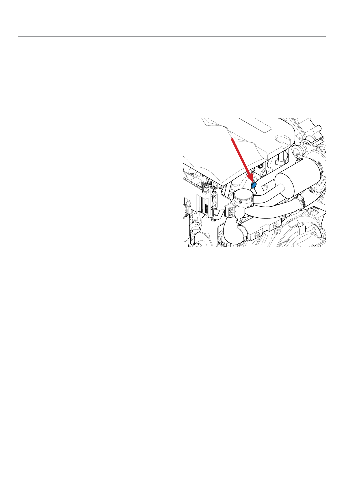
Coolant fi lling
I Attention! : Do not check the coolant level when the
engine is hot. Pressurised coolant can spurt and cause
serious burns. Carry out this work with the engine stopped
and cold. Only use new coolant when replenishing or adding
coolant.
Regularly check the coolant level.
• Turn the fi ll cap A situated on the heat exchanger to
its fi rst stop to release the system pressure and then
remove the cap.
• Check the coolant level: it must be between 1 and 2 cm
below the edge of the exchanger.
• Top up if necessary. Fill the heat exchanger slowly with
coolant up to the maximum level in order to let the air
escape.
• Run the engine for few minutes and keep it idling. Stop
the engine, wait a few moments, then check the coolant
level again. Fill again if necessary.
Page 21

A
Maintenance
Cooling circuit - coolant
Draining the cooling circuit
The coolant in the cooling circuit must be drained in order to
remove the various deposits that can build up in the circuit.
• Start the engine and let it run at idle for few minutes.
• Stop the engine, remove the key from the instrument
panel, and let the engine cool to avoid burns.
• Place a pail under the drain cap A and untighten it.
• Let the coolant run out until the exchanger is empty.
• Clean the inside of the heat exchanger by following the
instructions below before closing the cap.
Rinsing the cooling circuit
The cooling circuit must be rinsed after emptying.
• Remove the fi ll cap situated on the top of the heat
exchanger and the drain cap.
• Clean the inside of the heat exchanger with clean water
by placing a hose in the fi ll cap.
• Continue until clean water runs from the drain orifi ce.
• Close the cap then refi ll with coolant.
21
Page 22

Maintenance
22
Cooling circuit - seawater
I Attention ! : When the craft is in the water, there is a risk of water penetrating the craft when working on the seawater
circuit. Water can penetrate the craft via circuit components found below the waterline. Close the seawater intake valve (if
fi tted) or prevent water discharge before working on this circuit!
Cleaning the seawater circuit is essential to preventing the formation of deposits and salt crystals. The presence of a
seawater fi lter between the pump and the water intake is mandatory. Check and clean the fi lter regularly.
A
Cleaning the seawater fi lter
The seawater fi lter is an optional component. These
instructions are given as an example only.
• Check the condition of the seawater fi lter with the engine
stopped. If deposits have formed, remove the fi lter in
order to clean it.
• Remove the cover and then the fi ltering part A. Remove
all the debris on the housing.
• Rinse the fi lter and the housing with fresh water and
check the condition of the seal, then re-install all the
components and check there are no water and/or air
leaks in the circuit when operational.
Draining the seawater circuit
• Close the seawater intake valve.
• Place a pail under the drain cap A
• Remove the cap A
• Let the water fl ow in the pail
• Refi t the cap
• Drain also the exhaust circuit. A small amount of water
may remain in the bottom of the Waterlock box.
A
Page 23

Maintenance
Cooling circuit - seawater
Replacing the seawater pump rotor
The seawater pump rotor is an essential component. It
must be replaced regularly along with the seal. A worn rotor
could crack and damage the cooling system. Always have a
replacement rotor on board the craft.
• Close the seawater intake valve.
• Remove the seawater pump cap A and the seal B, then
remove the rotor C without damaging it.
• Check the condition of the rotor: replace it if even the
most minor defect is noted.
• Clean the elements retained.
• Fit a new rotor by turning it clockwise.
• Lubricate the pump casing and the inside of the lid with
waterproof grease for rubber.
• Refi t the water pump cap using a new seal.
• Open the seawater intake valve and then start the engine to check that the circuit is leak-tight.
23
B
A
C
Page 24

Maintenance
24
Air fi lter
I Attention! : Carry out these operations when the engine
is stopped and cold.
The air fi lter essentially reduces the level of noise made by
the engine and purifi es the air injected into the combustion
chamber.
If the fi lter is too clogged, replace it. If it is not:
• Remove the hose retaining ring and remove the fi lter.
• First clean the fi lter with compressed air and then rinse
it with clean water.
• Let it dry completely at ambient temperature and then
replace it.
Page 25

B
A
Maintenance
Engine electrical system
I
Attention! : Stop the engine and the cut the battery
supply before working on the electrical circuit.
Alternator belt
Make this check after running the engine when the belt is
slightly hot.
I Attention! : Some parts of the engine can be extremely
hot.
To replace the belt, act on the tensioner A until the holes B
are aligned then use a locking pin to lock it. You can then
take off and replace the belt.
After replacing it, move the tensioner A to release the
locking pin and remove it in order to tighten the belt. Then
release the tension on the automatic tensioner A which will
then apply the correct tension on the belt.
Check the electrolyte level.
The starter battery must remain clean and dry. Oxidation or the deposit of impurities on the battery and on its
terminals may lead to short circuits, voltage drops and
premature discharging, notably in wet weather.
The battery terminals and the cables must be cleaned
with a brass brush in order to remove any oxidation.
Tighten the cable terminals and lubricate them with appropriate grease.
If the battery is replaced, use a battery with similar specifi -
cations to the previous one.
If starting with an emergency battery and connection cables, proceed as follows:
- Connect the emergency battery to the main battery
by connecting the + to the + and the – to the -. When the
engine has started, remove the connection cables.
You should disconnect the 2 battery cables when:
- You use a battery charger
- Before carrying out any work on the electrical equip-
ment
- Before carrying out any welding work
Changing fuses
The protective fuses in the electrical system are disposable.
These blown in the event of a voltage surge or a shortcircuit in order to prevent any damage to the parts. In the
event some anomaly has caused a fuse to blown, fi nd the
cause before changing the fuse. Always use a fuse with the
properties as the one being replaced
25
Page 26
Maintenance
26
Protection against corrosion - Zinc anode
When at least two different kinds of metal are immersed
in seawater, polluted water or water with a high mineral
content, a chemical reaction occurs and an electrical current
is established between the metals.
This electrical current leads to the metal that is more active
from a chemical point of view, or more anodic metal being
eroded. If this is not controlled, this galvanic erosion can
seriously damage the parts and propulsion system that are
exposed to water.
In order to protect the engine and the seawater cooling
system from corrosion, the engine is fi tted with two sacrifi cial
anodes located on the end cover of the exchanger.
To remove the anode
• Let the engine cool down
• Close the seawater intake valve
• Drain the seawater system
• Remove the set formed by a cap, a seam and the anode.
Remark: Remove the deposits from the surface of the anode
using glass paper before determining the level of erosion. Do
not use a soft steel brush as this could leave deposits that
are likely to speed up corrosion.
If more than 50% of the anode has been used up, replace
both it and the seal.
I Attention! : Screw the anode cap back on tightly and do
not forget to re-open the seawater intake valve.
Page 27

Maintenance
Protecting the engine during periods of inactivity
27
A set of operations will protect the engine during long periods of non-use. We recommend that you have these
winterization operations carried out by a Nanni Diesel
authorised workshop.
During short periods of inactivity, carry out the following operations:
• Check all the electrical contacts and protect them with
an anti-oxidant spray if necessary.
• Check the electrolyte level and that the battery is
charged.
• Take the engine to its operating temperature (70-80°C)
at least once a month.
For long periods of inactivity, carry out the operations below. This treatment is effective for 6 months. If the period of
inactivity is extended, repeat this treatment.
1. Drain the engine and gearbox oil, change the oil fi lter
and fi ll with new oil. Drain and replace the coolant.
2. Drain the fuel prefi lter and replace the cartridge (if
equipped).
3. Change the fuel fi lter and drain the fuel circuit with
storage fuel.
4. Inspect the air fi lter. Change it if necessary.
5. Check that the injection pump rack moves freely (if
equipped).
6. Inspect the control cables (make sure the engine is at
idle and the gearbox in neutral).
7. Remove all the mechanical parts and the ancillary
applications that could be damaged during the noload operation of the engine.
8. Inspect the belts. Replace it if necessary.
9. Start the engine and let it operate few minutes without load.
10. Run the engine at 1500-1800 rpm for 15 minutes until
the operating temperature (70-80°C) is reached.
11. Stop the engine and remove the start key from the
panel.
12. Let the engine cool down to avoid the risk of burns.
13. Block all the openings (admission, exhaust, fuel line,
air valve).
14. Loosen belts.
15. Remove and store the impeller of the sea water pump
in a hermetic opaque container. Indicate clearly with
a note on the engine «IMPELLER OF RAW WATER
PUMP MISSING».
16. Remove the battery.
17. Spray an anti-damp spray on the engine and the
electric parts (starter, alternator, wire harness connectors and panel).
18. Clean the hold and Install a dehumidifi er.
19. Grease the control cables (if equipped)
Restarting the engine
After a period of inactivity, carry out the following operations before restarting the engine:
• Check that the battery is charged and the level of the
liquid. Check that the electrical contacts are intact and
working correctly.
• Check the oil level. If necessary fi ll the oil tank or drain
the oil according to the intervals given in the Silverwake
booklet.
• Replace the oil fi lter
• Check the coolant level. Fill with coolant if necessary
or drain the coolant according to the intervals given in
the Silverwake booklet.
• Replace the fuel fi lter according to the intervals given
in the Silverwake booklet.
• Replace the air fi lter according to the intervals given in
the Silverwake booklet.
• Re-tighten the belt.
• Check the tightness of the connections.
• Check the integrity of the impeller of the seawater
pump and put it back into the pump.
• Remove the exterior protection treatment and all the
covers.
• Start the engine and if no defaults appear, let it run for
few minutes without load.
• Stop the engine and check the engine oil and coolant
levels. Check for leakage.
Prolonged storage
For prolonged storage before or after being used for the
fi rst time, a specifi c set of measures should be adopted.
Contact your Nanni Diesel authorised engineer.
Page 28

2828
Faults and probable causes
Engine does not start / starter does not turn
Faults Solution
Circuit breaker is open or fuse has blown
Check and re-install the circuit breaker or replace the
fuse or replace the circuit breaker
Electrical circuit breaker is not working
Battery switch is open (battery main switch) Close the switch
Electrical connections are faulty
Check the electrical connections and wires (especially the
battery cables) Clean and tighten the connections
Battery faulty Test and charge or replace the battery if faulty
Starting procedure defective Read and implement the starting procedure
Fuel tank empty or fuel valve closed Fill the tank or open the valve
Fuel pump faulty Replace the pump
Fuel fi lters clogged or water present
Clean or replace the fuel fi lters or drain the water from the
prefi lter then drain the circuit
Fuel contaminated or too old Drain the tank if contaminated and fi ll with clean fuel
Fuel pipe or air pipe of tank blocked or bent
Replace the bent pipes or blow in compressed air to
remove the obstruction
Air present in fuel injection system Drain the injection system
Fault-fi nding
This section helps you to understand the different problems that may arise on your engine. The safest way to correct the
problems you may encounter, however, is to contact a qualifi ed Nanni Diesel dealer. Some operations must be carried out
by a qualifi ed Nanni Diesel authorised dealer. These operations are marked in bold in the tables below.
This non-exhaustive list serves as a tool in emergencies and should never be considered a repair procedure. Some of the
components listed may not be part of your engine.
Page 29

29
Dépannage
Faults and probable causes
Engine overheats / Engine coolant temperature too high
Faults Solution
Seawater valve is closed Open the seawater valve
Seawater fi lter is clogged Close the seawater valve and clean the fi lter
Seawater pump is sucking air
Check the position and seal of the seawater fi lter cover
and the suction hose
Coolant circuit pump belt is slack or faulty Re-tighten or replace the belt
Coolant pump is faulty Replace the pumpe and the belt
Seawater pump rotor is faulty Replace the rotor
Insuffi cient coolant
Fill with coolant and check that the cooling system is leaktight
Thermostat is malfunctioning Replace the thermostat
Cooling system is blocked Locate the problem and clean
Closed cooling circuit is dirty Clean and rinse
Loss of pressure in the closed cooling circuit
Check there are no leaks. Clean, inspect and check the
fi ll cap
Coolant is unsuitable
Use the recommended coolant (see technical
specifi cations)
Page 30

Technical specifications
3030
* At engine fl ywheel, as per ISO 8665 -1
Certain specifi cations may vary depending on your order.
The recommended cruising speed is 200 rpm under the maximum rpm speed at full throttle
ENGINE SPECIFICATIONS H4.115 H4.130 H4.150 H4.170
Cycle 4 strokes Diesel
Max. power - kW (hp)* 84.6 (115) 97 (130) 111 (150) 126 (170)
Number of cylinders / Arrangement 4 in line
Displacement (cm
3
) 1991
Distribution 4 valves per cylinder
Compression rate 17.5 : 1
Aspiration Turbocompresseur et intercooler
Bore x stroke (mm) 83 x 92
Maximum rpm speed at full throttle (rpm)* 3000 ± 50 tr/min 4000 ± 50 tr/min
Idle rpm speed (rpm)* 700 ± 50 tr/min 700 ± 50 tr/min
No load rpm speed (rpm)* 3120 ± 50 tr/min 4120 ± 50 tr/min
Theoric fuel consumption (l/h) 21.8 @ 3000 tr/min 29.5 @ 4000 tr/min 34.1 @ 4000 tr/min 37.4 @ 4000 tr/min
Weight without gearbox (kg) 250
INJECTION SYSTEM H4.115 H4.130 H4.150 H4.170
Injection Direct Common Rail
Injection order 1-3-4-2
Injection pump BOSCH Common Rail (CRS 2.0)
Injection pressure (bar) 1600
LUBRICATION H4.115 H4.130 H4.150 H4.170
Type Forced by pump
Pressure at idle rpm speed (bar) 1 - 4
Capacity (engine on an horizontal axis) 3.2 mini - 4.2 maxi
COOLANT H4.115 H4.130 H4.150 H4.170
Pressure setting of the plug (bar) 1.2
Coolant capacity (50% water - 50% antifreeze) 7.7
ELECTRICAL H4.115 H4.130 H4.150 H4.170
Starter (kW) 2
Battery capacity (Ah) 100-120
Alternator (V/A) 12V / 110A
Page 31

31
Page 32

Nanni Industries S.A.S.
11, Avenue Mario e - Zone Industrielle
BP 107- 33260 La Teste France
Tel : + 33 (0)5 56 22 30 60
Fax : +33 (0)5 56 22 30 79
E-mail : contact@nannidiesel.com
© 2009 - Nanni Industries S.A.S
The images, text and information contained in this document are based on the product specifi cations
at the time this document was published. Nanni Diesel reserves the right to alter this document without
notice.
Page 33

Notice de conduite
Moteurs Diesel marin
H4.115
H4.130
H4.150
H4.170
970315363
01032011-F
Page 34

Sommaire
2
Précautions de sécurité .........................................................................................................3
Présentation ............................................................................................................................6
Plaques signalétiques .................................................................................................................. 6
Équipements supplémentaires.....................................................................................................6
Garantie ....................................................................................................................................... 7
Responsabilité environnementale ................................................................................................ 7
Préparation avant la mise en service .......................................................................................... 7
Approvisionnement en combustible ............................................................................................. 7
Comportement de l’embarcation .................................................................................................. 7
Tableaux de bord ....................................................................................................................8
Voyants & alarmes ....................................................................................................................... 9
Levier de commande ................................................................................................................... 9
Principaux organes du moteur .............................................................................................10
Contrôle de l’installation .......................................................................................................11
Fonctionnement du moteur ..................................................................................................12
Avant le démarrage .........................................................................................................12
Démarrage du moteur .....................................................................................................12
En fonctionnement ...............................................................................................................13
Passage de vitesse marche avant / arrière................................................................................ 13
Rodage ...................................................................................................................................... 13
Arrêt du moteur ....................................................................................................................13
Arrêt d’urgence ................................................................................................................13
Après l’arrêt du moteur ....................................................................................................13
Entretien .................................................................................................................................14
Contrôles quotidien ..............................................................................................................15
Système d’alimentation ........................................................................................................16
Purge du circuit de carburant ..........................................................................................16
Remplacement du fi ltre à gazole .....................................................................................16
Remplacement du préfi ltre à carburant ...........................................................................17
Vidange de l’eau dans le préfi ltre à carburant .................................................................17
Système de lubrifi cation .......................................................................................................18
Contrôle du niveau et ajout d’huile moteur ......................................................................18
Remplacement de la cartouche de fi ltre à huile ..............................................................18
Vidange de l’huile moteur ................................................................................................20
Circuit de refroidissement - liquide de refroidissement ........................................................20
Remplissage de liquide de refroidissement .....................................................................21
Vidange du circuit de refroidissement .............................................................................21
Rinçage du circuit de refroidissement .............................................................................21
Circuit de refroidissement - eau de mer ...............................................................................22
Nettoyage du fi ltre à eau de mer .....................................................................................22
Vidange du circuit d’eau de mer ......................................................................................22
Remplacement du rotor de la pompe à eau de mer ........................................................23
Filtre à air .............................................................................................................................24
Système électrique du moteur ..............................................................................................25
Contrôle niveau de l’électrolyte .......................................................................................25
Changement des fusibles ................................................................................................25
Protection contre la corrosion - Anode de zinc .....................................................................26
Protection du moteur en cas d’inactivité ...............................................................................27
Remise en service du moteur ...............................................................................................27
Dépannage .............................................................................................................................28
Caractéristiques techniques ...............................................................................................30
Page 35

Précautions de sécurité
Lisez ce chapitre attentivement, il concerne votre sécurité.
La plupart des accidents sont dus au non respect des règles
de sécurité élémentaires. Soyez conscient des risques que
peut comporter la manipulation de votre moteur et veillez
à prendre les précautions nécessaires pour vous, votre
entourage et votre équipement.
Ce manuel comporte des indications de sécurité et des
informations importantes.
Celles-ci sont présentées ainsi :
I Danger ! : Ce symbole signale des risques d’accidents
et de blessures corporelles sévères, de dégâts matériels
importants ou de pannes mécaniques graves en cas de
non respect des instructions.
I Attention ! : Signale un danger corporel et/ou matériel
lors de la manipulation d’un composant.
Remarque : Indique qu’une information importante est à
prendre en compte, afin de vous faciliter une manipulation
ou lors de cas particuliers.
L’utilisation et la manipulation d’un moteur comportent des
risques et peuvent s’avérer très dangereuses. Certaines
interventions demandent des connaissances et un matériel
spécifique, celles-ci doivent être réalisées par un personnel
agréé Nanni Diesel ou par un professionnel. Si vous devez
intervenir sur le moteur, respectez scrupuleusement les
consignes de sécurité contenues dans ce manuel.
Diverses informations figurent directement sur le moteur sous forme de logo. Celles-ci ont pour but de vous renseigner
rapidement sur la localisation de certains composants et de vous prévenir contre d’éventuels dangers lors d’une intervention. Veillez à toujours garder visible ces indications, les remplacer si nécessaire.
Localise où vérifier le niveau de liquide de refroidissement.
Indique qu’il est primordial de lire attentivement la notice avant toute manipulation du moteur.
Localise des dangers d’ordre électrique.
Localise les parties chaudes où les risques de brûlures sont importants.
Cette icône indique un risque d’incendie.
Stipule qu’il est fortement déconseillé de fumer, de produire des flammes ou des étincelles à proximité.
Localise une zone où les fluides sont sous-pression.
Localise les parties rotatives dangereuses
Localise le ou les orifices de désaération (purge d’air).
Localise où vérifier le niveau d’huile moteur.
Localise l’orifice de vidange de liquide de refroidissement.
Localise l’orifice de vidange du réservoir d’huile.
3
Page 36

I Gaz d’échappement
Les gaz d’échappement contiennent du monoxyde de
carbone. Ce gaz incolore et inodore est extrêmement nocif
et peut entraîner un empoisonnement pouvant causer des
pertes de conscience ou la mort. Les premiers symptômes
d’une intoxication au monoxyde de carbone sont les
suivants :
• Vertige
• Nausée
• Maux de tête
• Palpitation au niveau des tempes
• Vomissement
• Fatigue et endormissement
• Crispation musculaire
Si vous ou tout autre personne se trouvant à proximité du
moteur ressent l’un de ces symptômes, quittez la zone de
fonctionnement du moteur et mettez-vous à l’air libre. Si
les symptômes persistent, consultez un médecin et faites
vérifier votre moteur.
I Risque de choc électrique
Ne jamais toucher les connecteurs électriques lorsque le
moteur est en marche ou lorsque le système est branché
sur une prise de quai. La tension aux bornes de ces
connecteurs peut être mortelle.
N’intervenez pas sur le moteur sans protections : lunettes
et gants de protection, tapis isolants, etc.
Coupez toujours le moteur et le courant avant toute
intervention sur le système électrique. Isolez l’alimentation
de prise de quai de l’ensemble des équipements du circuit
électrique.
Assurez-vous que vos vêtements et votre peau ne soient pas
humides ou moites lorsque vous manipulez un équipement
électrique. Enlevez vos montres, bracelets, bijoux lorsque
vous intervenez sur un équipement électrique.
La manipulation d’un condensateur encore chargé est
dangereuse et peut causer une électrocution.
I Risques de brûlures
Ne jamais toucher les parties chaudes du moteur ou le
circuit d’échappement.
Un moteur en marche chauffe beaucoup : le coude et tuyau
d’échappement, le turbocompresseur, le démarreur, carter
d’huile, l’huile, le liquide de refroidissement circulant dans
les durites et flexibles sont chauds et peuvent bruler.
Vérifiez toujours le niveau de liquide de refroidissement
avant de démarrer le moteur.
Les liquides éjectés sous pression peuvent provoquer de
graves blessures.
Libérez toute pression dans les circuits avant de retirer les
bouchons.
Ne pas ouvrir les bouchons des circuits de liquide de
refroidissement et d’huile lorsque le moteur tourne et/ou
lorsqu’il est chaud.
Ne jamais démarrer ni faire tourner le moteur lorsque le
bouchon de remplissage d’huile n’est pas vissé, de l’huile
chaude pouvant être projetée.
En cas de contact d’un de ces fluides, consultez
immédiatement un médecin.
Si le moteur chauffe trop, coupez le contact et le courant et
attendez que le moteur refroidisse avant de le manipuler.
I Risques d’incendie
Ne fumez pas et n’approchez pas de flammes ni d’étincelles
à proximité du moteur ou de toute source potentielle de
vapeurs et de liquides inflammables.
Ne faites pas tourner le moteur sans filtre à air.
Ne faites pas tourner le moteur dans une zone de stockage
de matériaux inflammables, explosifs, ou comportant une
présence de gaz. Remisez les liquides inflammables hors
du compartiment moteur.
Nettoyez immédiatement les liquides renversés sur vous
ou au sol et gardez le compartiment du moteur propre et
accessible afin de minimiser les risques d’incendie. Soyez
prudent, le gasoil peut brûler.
I Risques d’explosion
Une explosion due à des vapeurs de gasoil peut causer de
graves blessures ! Suivez scrupuleusement les règles de
sécurité lors du plein de carburant.
Ouvrez et ventilez le lieu de stockage du moteur après
avoir fait le plein. Vérifiez qu’il n’y a pas de vapeurs ou de
fuites de gasoil avant de démarrer le ventilateur (si équipé).
Mettez le ventilateur en marche durant 5 minutes avant de
démarrer le moteur.
Toutes les vapeurs de gasoil sont inflammables et
explosives. Soyez prudent lors de la manipulation et le
stockage de gasoil. Stocker le gasoil dans un endroit ventilé
à l’écart de sources d’étincelles et de flammes, hors de
portée des enfants.
Arrêtez le moteur avant de faire le plein de carburant et ou
de lubrifiant. Ne fumez pas et n’approchez pas de flamme
pendant le plein de carburant et/ou de lubrifiant. Portez des
gants pour rechercher une fuite éventuelle.
Ne pas modifier ou détériorer le circuit de carburant. Fermez
le circuit de carburant lors de toute intervention sur celui-ci.
Assurez-vous d’avoir toujours à portée de main un extincteur
adéquat en état de marche.
Précautions de sécurité
4
Page 37

I Démarrage accidentel
Un démarrage accidentel peut être la cause de graves
blessures et causer la mort !
Déconnectez la batterie avant d’intervenir sur le moteur.
Assurez-vous que personne ne soit à coté du moteur ou en
train d’intervenir sur celui-ci avant de le démarrer. L’hélice
en mouvement peut provoquer de graves blessures.
Assurez-vous que toutes les protections soient en place
avant de démarrer le moteur.
I
Risques d’explosion des batteries
L’explosion d’une batterie peut causer de graves blessures
et causer la mort !
Ne pas fumer ou approcher une source de flamme ou
d’étincelle près des batteries. Celles-ci produisent de
l’hydrogène, qui peut s’allumer et exploser au contact d’un
arc électrique ou d’une flamme. Eteignez tous les appareils
électriques à proximité lorsque vous intervenez sur les
batteries.
Ventilez correctement le compartiment de stockage des
batteries.
Évitez de toucher les bornes de la batterie avec des outils
en métal, afin de ne pas créer d’étincelles qui pourrait
causer une explosion. Enlevez vos bagues, bracelets et
colliers avant de manipuler les batteries.
I Acide de batterie
L’acide contenu dans les batteries peut causer de graves
blessures et causer la mort !
Lors de l’entretien des batteries, portez des gants et des
lunettes de protection. Une batterie contient de l’acide
sulfurique extrêmement corrosif.
En cas de contact avec la peau, rincez abondamment à
l’eau douce et contactez un médecin.
De l’acide peut jaillir des batteries lors de leur manipulation.
I Gaz d’échappement
Assurez-vous que le circuit d’échappement expulse
correctement les gaz émis par le moteur. Vérifiez
régulièrement que le circuit d’échappement n’a pas de fuite
et que le coude d’échappement soit bien fixé.
Faites fonctionner le moteur dans un espace bien aéré
et ventilé, à l’écart des personnes. Faites fonctionner le
ventilateur lorsque le moteur est en marche.
I Partie en rotation
Les parties en rotation peuvent être extrêmement
dangereuses et causer de graves blessures et la mort !
N’intervenez pas sur le moteur lorsque celui-ci est en
marche. Si une intervention moteur en marche est
absolument nécessaire, veillez à ne pas toucher une partie
chaude ou en rotation.
Les vêtements amples, les cheveux ou les objets peuvent
être aspirés et/ou entraînés et causer de graves blessures
ou d’importants dégâts matériels.
Ne pas porter de bracelets, colliers ou bagues lors d’une
intervention sur un moteur.
Assurez-vous que les boulons et les vis soient bien serrés
et que les protections soient bien en place.
Ne pas vérifier les niveaux des fluides ou la tension de la
courroie de l’alternateur lorsque le moteur est en marche.
I Levage du moteur
Pour soulever le moteur, utiliser les anneaux de levage
placés sur l’appareil.
Veillez constamment à la solidité et à l’état général de
l’équipement de levage. Utilisez un appareillage adéquate
(câbles, poutres, engins, etc.) pour lever votre moteur,
vérifiez que celui-ci est capable de soulever l’ensemble.
Les câbles et chaînes de levage doivent pouvoir manoeuvrer
parallèlement les uns par rapport aux autres.
N’oubliez pas que tout équipement supplémentaire monté
sur le moteur peut modifier son centre de gravité.
Lors du levage, l’ensemble doit rester le plus parallèle au
sol possible.
I Maintenance et pièce de rechange
Les moteurs Nanni Diesel sont conçus afin de respecter
différentes normes d’émissions tout en assurant une durée
de vie et une fiabilité maximale.
Un entretien régulier et le remplacement des éléments par
des pièces d’origine Nanni Diesel permettent de garder le
moteur dans de bonnes conditions de fonctionnement.
Ces pièces peuvent être commandées auprès de tous les
revendeurs Nanni Diesel agréés à travers le monde.
I Produits chimiques
Les différents fluides utilisés pour le fonctionnement du
moteur constituent un danger pour la santé.
Lisez attentivement les instructions figurant sur l’emballage
de ces produits et veillez toujours à ce que la ventilation
dans la cale soit bonne.
I Sécurité à bord
Maîtrisez parfaitement le code nautique et les règles de
sécurité en mer ; n’hésitez pas à contacter les autorités ou
les organisations compétentes.
Évitez de faire des manœuvres trop brusques qui pourraient
surprendre vos passagers.
Des remous créés à la poupe du bateau peuvent aboutir
à un phénomène d’aspiration des gaz d’échappement
dans la cabine. Dans ce cas là n’ouvrez aucune trappe ou
soupape du bateau, et essayez de changer de réglages de
navigation (vitesse, répartition des masses ).
Vérifiez l’équipement de sécurité à bord avant chaque
sortie. Se référer au matériel obligatoire par pays.
5
Précautions de sécurité
Page 38

Présentation
Vous avez choisi un moteur Nanni Diesel, merci de
votre confiance !
Pour l’entretien de votre équipement, adressez-vous à un
revendeur agréé Nanni Diesel. Vous pouvez retrouver la
liste des revendeurs sur notre site Internet à l’adresse :
www.nannidiesel.com
Les moteurs Nanni Diesel sont issus de nombreuses
années d’expérience dans le développement de moteurs
marins et d’équipements destinés à un usage en pleine
mer. Ces équipements ont été conçus dans le but de vous
faciliter la vie à bord tout en vous offrant un maximum de
sécurité et une fiabilité accrue.
Cette notice d’utilisation concerne les moteurs
• H4.115
• H4.130
• H4.150
• H4.170
Ces moteurs ont été développés à partir des toutes
dernières innovations en matière de moteurs diesel. Leurs
principales caractéristiques étant une injection directe à
rampe commune (Common Rail), 4 soupapes par cylindres,
un turbocompresseur et 2 arbres d’équilibrage.
Leur système d’injection est contrôlé électroniquement
par un module de commande (ECU). Ce module gère
la quantité de gasoil injecté en fonction de différents
paramètres.
Ces moteurs sont également équipés de fusibles de
protection du circuit électrique qui se déclenchent en cas
de surcharge de courant ou de court-circuit, afin d’éviter
d’endommager les composants
Avant toute manipulation , assurez-vous d’avoir en votre
possession le manuel correspondant à votre moteur. La
plaque signalétique vous indique la dénomination exacte
de votre moteur. Si le manuel en votre possession n’est
pas le bon, contactez votre revendeur agréé Nanni Diesel.
Lisez attentivement et dans son ensemble le contenu du
présent manuel ainsi que celui de la transmission avant de
démarrer le moteur.
Apportez un soin particulier aux informations relatives à
la sécurité des personnes. Le présent manuel doit être
disponible en permanence sur le lieu d’utilisation du moteur.
Nous vous conseillons de contrôler visuellement l’état
général de votre moteur et de la transmission avant et
après chaque utilisation, afin de vous familiariser avec les
différents équipements et détecter plus facilement toute
fuite de carburant, d’huile ou de liquide de refroidissement,
ainsi que toute usure anormale des principaux organes.
Toutes les informations et spécifications contenues dans
ce manuel sont basées sur les données techniques en
application au moment de la publication. Des modifications
et mises à jour peuvent être introduites sans préavis de la
part de Nanni Diesel.
Certaines images, schémas ou équipements décrits dans
ce manuel peuvent ne pas représenter exactement (ou ne
pas faire partie) de la fourniture de votre moteur.
Plaques signalétiques
Votre ensemble de propulsion possède deux plaques
signalétiques : une pour le moteur, et une autre pour la
transmission.
Veillez à garder ces plaques accessibles et en bon état.
Notez le numéro de série et la désignation du moteur et
de la transmission afin de les conserver. Ces numéros
vous seront utiles en cas d’intervention sur le moteur, de
commande de pièces ou de recours en garantie.
La plaque signalétique du moteur se présente comme suit :
TYP indique la désignation commerciale du moteur
(exemple: H4.150).
NR indique le numéro de série du moteur.
CODE récapitule les différentes spécifications de votre
moteur.
Équipements supplémentaires
Votre moteur peut être équipé d’équipements optionnels
(alternateurs, générateur intercalé, propulsion hybride,
pompes, Trolling valve, etc.)
Reportez-vous à la documentation supplémentaire relative
à ces équipements ou contactez votre revendeur agréé
Nanni Diesel pour plus d’informations.
6
TYP
NR
CODE
Page 39

Garantie
Le propriétaire du moteur est responsable de tous les
examens de sécurité, de l’entretien ainsi que du respect
des consignes de maintenance telles que décrites dans
ce manuel et dans le carnet de garantie Silverwake. La
performance et la fiabilité de votre moteur reposent sur
l’application de ces consignes.
La maintenance doit être confiée à un spécialiste agréé par
Nanni Diesel. Les opérations de maintenance réalisées
par un représentant agréé conditionnent la validité de la
garantie.
L’usure des composants ainsi que les frais d’entretien
découlent naturellement de l’utilisation du moteur, ils ne
constituent donc pas des défauts de fabrication ou de
matériel aux termes de la garantie.
Nous déconseillons fortement toute modification du réglage
du régime moteur, ainsi que toute modification technique
(accessoires, pièces de rechange, équipements attelés,
etc.) non-agréée par Nanni Diesel.
Toute modification entraînera l’annulation de la garantie car
nous ne pouvons engager notre responsabilité pour des
interventions sur lesquelles nous n’avons aucun contrôle.
Responsabilité environnementale
Nanni Diesel développe ses moteurs afin qu’ils aient une
incidence minimum sur l’environnement et une durée de
vie maximale.
Cependant, cet objectif n’est réalisable que grâce à votre
pleine collaboration.
Nos directives d’utilisation et d’entretien sont là pour vous
guider au mieux afin de protéger votre moteur et d’adopter
un comportement responsable vis-à-vis de l’environnement.
Veillez à n’utiliser que les carburants et huiles préconisés
dans ce manuel. L’utilisation d’un autre type de carburant
ou d’huile peut provoquer d’importants dysfonctionnements
du moteur : augmentation de la consommation, réduction
de la durée de vie du moteur, rejet plus important de gaz
d’échappement.
Lors de la vidange d’huile et du changement de filtre à
huile ou à carburant, veillez à déposer les déchets dans un
conteneur prévu à cet effet.
Ces fluides rejetés dans la nature causent des dégâts
importants à l’ensemble de la faune et de la flore.
Demandez un kit absorbant au pompiste en cas de rejet
accidentel d’hydrocarbures dans l’eau.
Préparation avant la mise en service
Lorsque le moteur a été installé à bord, et avant d’enlever
les protections obturant les différents orifices, nettoyez la
surface extérieure de l’ensemble.
Pour des raisons liées au transport, certains de nos
moteurs sont livrés vides de liquides de fonctionnement,
dans tous les cas, il faut impérativement :
• Contrôler les niveaux et si besoin effectuer le plein
d’huile du moteur.
• Effectuer le plein de liquide de refroidissement de
l’échangeur, effectuer les opérations de dégazage.
• Vérifier la tension des courroies.
• Vérifier le serrage des différents raccords et bouchons
de vidange (eau et huile).
• Vérifier le serrage des cosses aux bornes de batterie,
coupe-circuit, raccordement des rallonges, niveau
d’électrolyte des batteries.
• Effectuer un dernier contrôle de la fixation ainsi qu’un
contrôle visuel de l’ensemble du moteur.
• Vérifier le fonctionnement du système de ventilation.
I Attention ! : Les moteurs diesel modernes sont des
équipements de précision, qui nécessitent l’utilisation de
carburant et de lubrifiant de haute qualité.
Approvisionnement en combustible
Lors de l’approvisionnement en combustible, s’assurer que
celui-ci ne contient aucun résidu; dans le cas contraire,
utiliser des filtres spéciaux.
Évitez d’employer du combustible mélangé avec de l’eau
ou d’autres substances sous peine d’endommager le
moteur.
Le rendement du moteur est influencé par la température
du combustible, par la température et l’humidité relative de
l’air d’aspiration ainsi que par l’altitude.
Comportement de l’embarcation
La répartition des masses à bord peut modifier le centre
de gravité du bateau et avoir des répercussions sur son
comportement en navigation.
L’état de la coque du bateau est également un facteur
déterminant. Une coque sale et/ou abîmée modifiera le
comportement du bateau.
L’hélice doit être adaptée au bateau et à l’utilisation qui
en est faite. Une hélice inadaptée est souvent la cause
d’un mauvais fonctionnement du bateau.
7
Présentation
Page 40

STOP
ON / STOP
START
RPM x 100
10
0
40
30
20
5
35
15
25
bar
0
2
4
6
8
10
0
40
80
120
160
psi
!
°C
40
60
80
100
120
°F
105
180
220
250
!
!
Présentation
8
Tableaux de bord
Le tableau de bord vous fournit des indications
importantes sur le moteur lorsque celui-ci fonctionne.
Vérifiez régulièrement ces informations lorsque le moteur
est en marche. La position ou l’aspect des instruments
représentés ici peut varier en fonction du type de tableau
de bord. Tous les tableaux de bord n’étant pas composés
de tous ces éléments.
Une fois le moteur démarré et en fonctionnement normal,
aucun des voyants présents sur votre tableau de bord
ne doit être allumé. Si l’un ou plusieurs de ces voyants
s’allume, arrêtez le moteur et faites le contrôler par un
représentant agréé Nanni Diesel.
1. Compte tours. Indique le régime de rotation du moteur
en tr/min.
2. Horamètre/Voltmètre. Enregistre les heures de
fonctionnement du moteur et indique la tension de charge
de la batterie du moteur lors de la mise sous tension
(contact).
3. Pression d’huile moteur. Attention, cet indicateur
n’indique pas le niveau d’huile moteur. Cet indicateur
indique la pression d’huile. Le voyant situé dans le compteur
s’allume et une alarme sonore se déclenche en cas de
chute de pression d’huile dans le circuit de lubrification.
Au ralenti, la pression est généralement plus basse.
I Danger ! : Si cette alarme se déclenche, arrêtez le
moteur - sauf en cas d’extrême urgence - et contactez un
revendeur agréé Nanni Diesel.
4. Température du liquide de refroidissement. Indique
la température du liquide de refroidissement. Le voyant
situé dans le compteur s’allume et une alarme sonore
se déclenche en cas de surchauffe dans le circuit de
refroidissement.
En utilisation normale et après la période de démarrage, la
température doit se situer entre 75 et 85 degrés Celsius.
I Danger ! : Si cette alarme se déclenche, abaissez le
régime jusqu’au ralenti quelques minutes et vérifiez que
l’eau de mer s’écoule bien par l’échappement. Si l’eau ne
s’écoule pas ou que la température ne baisse pas, arrêtez
le moteur - sauf en cas d’extrême urgence - et contactez un
revendeur agréé Nanni Diesel.
5. Interrupteur/clé de démarrage. Cet organe commande
le démarrage et l’arrêt du moteur. L’interrupteur à clé ON/
STOP permet la mise sous tension et l’arrêt du moteur, le
bouton START permet de le faire démarrer.
Certains tableaux (dits « à bouton ») peuvent ne pas être
équipés de clé de démarrage. Le bouton ON/STOP permet
de mettre le contact.
1
2
4
3
5
Page 41

!
9
Présentation
Voyants & alarmes
6. Préchauffage. Ce témoin est allumé lorsque les bougies
préchauffent les chambres de combustion (si votre moteur en est
équipé).
7. Charge batterie. Ce voyant s’allume lorsque le contact est
mis. Si celui-ci s’allume lorsque le moteur tourne, cela traduit un
défaut de charge de l’alternateur.
8. Voyant présence d’eau dans filtre à gasoil. Ce voyant
s’allume lorsqu’une trop grande quantité d’eau se trouve dans le
filtre à gasoil.
9. Voyant défaut système. Ce voyant indique la présence d’une
panne ou d’un défaut sur le système électronique. Si ce voyant
s’allume, contactez un représentant agrée Nanni Diesel.
10. Voyant surpression turbo. Ce voyant s’allume lorsque la
pression de l’air au niveau du turbo est trop importante.
Levier de commande
Sur la plupart des bateaux, le levier de commande du moteur
regroupe les fonctions de commande de régime et de changement
de vitesse (passage en marche avant / marche arrière).
Certains bateaux peuvent cependant être équipés d’une
commande d’inversion de marche ou d’une sécurité qui empêche
le moteur de démarrer tant que le levier n’est pas au point mort.
Renseignez-vous auprès du constructeur du bateau afin de
connaître le type de fonctionnement du levier de commande.
Sortie auxiliaire 12V tableau de bord
Les tableaux de bord de type A4, B4 et C4 sont équipés d’une
sortie auxiliaire de 12V / 3A.
Les interfaces d’adaptation reliant les tableaux de bord de type
Eco4, A4, B4 et C4 aux moteurs sont équipés d’un fusible de
protection.
Page 42

1. Alternateur
2. Courroie de l’alternateur
3. Démarreur
4. Filtre à air
5. Pompe haute pression du système rampe commune.
7. Filtre à gazole
8. Sortie d’échappement
9. Orifice de remplissage d’huile
10. Orifice de vidange d’huile
11. Jauge d’huile
12. Filtre à huile
13. Échangeur de chaleur
14. Orifice de remplissage liquide de refroidissement
15. Pompe à eau de mer
16. Bouchon de vidange échangeur
17. Unité de contrôle électronique
18. Suspensions souples
19. Turbocompresseur
20. Anneaux de levage
21. Fusibles
Présentation
10
Principaux organes du moteur
Certains équipements peuvent ne pas faire partie de votre moteur. Les moteurs équipés d’un système de refroidissement
par Keel Cooling ne sont pas équipés d’une pompe à eau de mer.
8
4
15
7
12
5
1
2
3
9
10
11
14
13
16
17
18
18
18
19
20
20
21
Page 43

11
Présentation
Contrôle de l’installation
I Attention ! : L’installation de votre moteur doit impérativement être faite par un Chantier naval agréé ou par un repré-
sentant qualifié de Nanni Industries conformément aux instructions de montage à bord. Vous pouvez cependant contrôlez
quelques points importants sur l’installation du moteur.
1. Bâti moteur
Le bâti moteur doit être rigide et capable d’absorber toutes
les contraintes dynamiques ainsi que le poids du moteur.
Il doit être solidaire de la coque et lié à celle-ci par une
surface aussi grande que possible.
Le moteur ne doit pas être incliné de plus de 15° lorsque le
bateau est à l’arrêt.
2. Ligne d’arbre
Le choix de l’ensemble de propulsion doit être fait en
fonction des contraintes liées au moteur, au bateau, et à
l’utilisation qui en sera faite.
3. Pot d’échappement (Waterlock)
Le pot d’échappement doit être positionné le plus près
possible du moteur et le plus bas possible.
4. Sortie de coque
La sortie de coque doit se trouver à 15 cm au dessus de la
ligne de flottaison. Le tuyau entre le pot d’échappement et
la sortie de coque doit former un col de cygne afin d’éviter
que de l’eau ne pénètre dans le système d’échappement
par la sortie de coque.
5. Anti-siphon
Il est obligatoire sur les bateaux dont le moteur se trouve
en dessous de la ligne de flottaison. L’anti-siphon doit être
inséré en fin de circuit d’eau de mer avant injection dans
le coude d’échappement et doit se situer au dessus de la
ligne de flottaison, entre 0.5 mètre et 2 mètres.
6. Filtre à eau de mer
Il doit toujours être placé au minimum à 15 cm au dessus
de la ligne de flottaison.
7. Vanne passe coque
Sur les voiliers et les bateaux ne dépassant pas 12 nœuds,
l’entrée d’eau doit être tournée vers l’arrière du bateau.
Sur les bateaux à moteur dont la vitesse dépasse 12
nœuds, l’entrée d’eau doit être tournée vers l’avant.
Cale moteur
La température à l’intérieur du compartiment moteur ne
doit pas excéder 50°C avec une différence de 20°C maxi
avec la température ambiante.
Pour les bateaux lents, la ventilation doit être assurée par
un ventilateur. La circulation de l’air frais devant se faire
de l’avant vers l’arrière. L’entrée d’air devant se situer sur
l’avant et en bas du compartiment moteur et la sortie à
l’arrière et en haut afin de permettre un brassage optimum
de l’air.
Installation électrique
Une installation électrique incorrecte ou défaillante peut
être la cause de courants de fuite qui peuvent altérer la
protection galvanique du moteur puis le moteur lui-même.
L’installateur doit veiller à prendre toutes les précautions
nécessaires afin d’assurer la protection du moteur contre
la corrosion.
4
3
5
6
2
1
7
Page 44

Fonctionnement du moteur
1212
Avant le démarrage
I Attention ! : Avant la mise en route du moteur,
s’assurer que la prise d’eau de mer est ouverte car il suffit
d’un fonctionnement à sec pendant quelques secondes
seulement pour détériorer le rotor de la pompe à eau de
mer.
N’utilisez jamais d’aérosol de démarrage ou d’équivalent.
Ces produits sont hautement inflammables.
Avant de tourner la clé de démarrage, et avant chaque
utilisation:
• Ouvrir le ou les panneaux de cale pour aérer la cale
complètement si elle n’est pas équipée d’un ventilateur.
Sinon faire marcher le ventilateur de cale 5 minutes.
• Vérifiez le niveau de carburant
• Vérifiez que votre levier de commande est bien au
point mort
• Ouvrez le robinet d’alimentation gazole et amorcer le
circuit si nécessaire
• Ouvrez la vanne de prise d’eau à la mer (si équipé)
• Vérifiez qu’il n’y a pas de fuites de carburant, d’huile ou
de liquide de refroidissement
• Vérifiez le niveau d’huile du moteur et faire l’appoint
si nécessaire avec l’huile préconisée. Consultez le
chapitre « Entretien » pour plus d’informations.
• Vérifiez le niveau du liquide de refroidissement et
faire l’appoint si nécessaire avec le liquide préconisé.
Consultez le chapitre « Entretien » pour plus
d’informations.
I Attention ! : Veillez à bien refermer le capot moteur et
remettre en place les éléments de protection avant la mise
en marche du moteur.
• Fermez le coupe-batterie (position marche - ON)
Remarque : Si votre moteur n’a pas fonctionné depuis
plusieurs mois ou si le circuit carburant a été purgé, utilisez
la pompe d’amorçage située sur le dessus du filtre à gasoil.
Celle-ci sert à remplir le circuit de carburant s’il est asséché
ou après le remplacement d’un élément du circuit.
I Danger ! : L’hélice en mouvement peut provoquer de
graves blessures, vérifiez que personne ne se trouve à
proximité de l’hélice avant de démarrer le moteur et ne
naviguez jamais près des baigneurs.
Démarrage du moteur
Remarque : Lors du premier démarrage, faites tourner le
moteur à vide et au ralenti pendant quelques minutes.
Si le moteur n’est pas utilisé régulièrement, mettez le
contact et faites tourner le moteur au ralenti jusqu’à ce que
la température de fonctionnement soit atteinte. Réalisez
cette opération au moins une fois par mois d’inactivité.
Effectuez les manipulations suivantes afin de démarrer
votre moteur en toute sécurité :
1. Positionnez le levier de commande au point mort
2. Insérez la clé dans le contact ON/STOP.
3. Tournez la clé vers la droite d’un quart de tour. Tous
les voyants s’allument et un signal sonore retentit. Cette
étape permet de vérifier le bon fonctionnement de ces
éléments. Au bout de quelques instants, seuls les voyants
alerte huile et charge batterie restent allumés.
4. Appuyez sur le bouton START, à mi-course pour
commencer le préchauffage. Maintenir 5 à 20 secondes,
selon la température ambiante. Appuyez à fond pour démarrer le moteur.
Tableau à bouton
Pour les tableaux à bouton (sans clé de contact) :
1. Appuyez sur le bouton ON/STOP. Tous les voyants
s’allument et un signal sonore retentit. Cette étape permet de vérifier le bon fonctionnement de ces éléments.
Au bout de quelques instants, seuls les voyants alerte
huile et charge batterie restent allumés.
2. Appuyez sur le bouton START, à mi-course pour
commencer le préchauffage. Maintenir 5 à 20 secondes,
selon la température ambiante. Appuyez à fond pour démarrer le moteur.
I Attention ! : Ne jamais appuyer sur le bouton START
lorsque le moteur est en marche.
Remarque : Consultez votre revendeur agréé Nanni Diesel afin de connaître les précautions à prendre en cas
d’utilisation du moteur dans un milieu froid.
I Attention ! : Si le moteur ne démarre pas au premier
essai, répétez la manœuvre en attendant 5 à 15 secondes
entre chaque essai, contact coupé. Ne jamais insister car
il y a risque de retour d’eau dans le moteur par le système
d’échappement.
Faites chauffer votre moteur à faible régime et à faible
charge pendant quelques minutes avant d’atteindre votre
vitesse de croisière.
Page 45

13
Fonctionnement du moteur
En fonctionnement
Régime de fonctionnement
Reportez-vous au chapitre « Spécifications techniques »
afin de connaître le régime de rotation nominal de votre
moteur.
Le fonctionnement du moteur à faible charge durant une
trop longue période peut entraîner entre autre une augmentation de la consommation d’huile. A faible charge,
la combustion du gasoil n’est pas complète, des dépôts
peuvent se former dans le moteur et le système d’échappement. Faites fonctionner le moteur à pleine charge 4 à 5
heures par an afin de brûler d’éventuels dépôts.
Vitesse de croisière
Afin de naviguer dans de bonnes conditions, réglez votre
vitesse de croisière à 200 tr/min de moins que le régime
maximum en pleine charge.
Passage de vitesse marche avant / arrière
I Danger ! : Ne jamais inverser le sens de marche lorsque
le bateau est à pleine vitesse. Les changements de vitesse
réalisés à un régime trop élevé peuvent endommager le
moteur et la transmission.
Effectuez les manipulations suivantes pour les manœuvres
de marche avant / marche arrière :
1. Abaissez le régime moteur au ralenti et attendez que
le bateau perde un maximum de vitesse
2. Amenez le levier au point mort, attendez quelques
secondes
3. Passez la commande en marche inverse et faites va-
rier la vitesse.
Rodage
Faites fonctionner votre moteur avec précaution lors des
50 premières heures de fonctionnement.
N’accélérez pas immédiatement après le démarrage sans
avoir laissé chauffer le moteur au ralenti quelques minutes
et n’atteignez le régime maximum que pendant de courtes
périodes.
Arrêt du moteur
Faites tourner votre moteur au ralenti et au point mort
quelques minutes avant de l’arrêter, particulièrement si le
moteur a tourné à haut régime et à forte charge.
Tournez la clef dans le sens inverse des aiguilles d’une
montre. Le moteur s‘arrête et tous les voyants s’éteignent.
Pour les tableaux à bouton, appuyez sur le bouton ON/
STOP puis relâchez-le.
Arrêt d’urgence
Il est possible d’arrêter le moteur manuellement si la
procédure d’arrêt standard ne fonctionne pas ou cas
d’urgence. Pour cela, couper l’arrivée de gasoil.
I Danger ! : Intervenir sur un moteur en marche est
extrêmement dangereux.
Après l’arrêt du moteur
Ouvrir le coupe-circuit (alimentation batterie fermée),
fermez la vanne de prise d’eau à la mer ainsi que
celle d’alimentation de carburant. Contrôlez l’état du
compartiment moteur afin de déceler d’éventuelles fuites.
I Danger ! : Même après avoir arrêté votre moteur, des
éléments restent chauds et en pression durant plusieurs
minutes. Limitez au maximum les interventions sur
l’ensemble de propulsion immédiatement après l’avoir
stoppé.
I Attention ! : En cas de remorquage du bateau, arrêtez
le moteur et fermez impérativement la vanne de prise à la
mer afin d’éviter le remplissage accidentel du moteur avec
de l’eau de mer.
BATEAUX BI MOTEURS : En cas de navigation sur un
seul moteur, fermez la prise d’eau à la mer du moteur
arrêté. Ne pas oublier de la rouvrir avant de redémarrer le
moteur.
Page 46

Entretien
1414
L’entretien régulier de votre moteur est essentiel afin
d’obtenir une fiabilité et une longévité optimales. La mise
en œuvre des opérations décrites dans les pages suivantes
et dans le carnet Silverwake vous permettra de prolonger
la durée de vie du moteur et de réduire son impact sur
l’environnement.
Durant la période de garantie, il est impératif que toutes les
interventions soit effectuées par un technicien spécialisé
agréé Nanni Diesel. Cependant, certains contrôles
réguliers, notamment ceux à effectuer à chaque utilisation,
ne peuvent être effectués que par l’utilisateur.
Certaines opérations vous sont expliquées dans les
pages suivantes afin de vous permettre d’intervenir sur le
moteur en cas d’urgence ou lorsque vous ne vous trouvez
pas à proximité d’un centre de réparation. Nous vous
recommandons cependant de faire contrôler toutes vos
interventions par un spécialiste agréé Nanni Diesel.
I Attention ! : Limitez au maximum les opérations lorsque
le moteur est en marche et/ou lorsque vous naviguez.
Cette notice d’utilisation ne décrit qu’une partie des
opérations de maintenance à réaliser. Retrouvez la liste
complète dans le carnet Silverwake. Les opérations
indiquées dans le carnet Silverwake doivent absolument
être réalisées par un technicien agréé Nanni Diesel.
Le tableau d’instrumentation vous indique combien de
temps votre moteur à fonctionné depuis son installation.
Remarque : Certains équipement sont optionnels et
peuvent ne pas faire partie de votre moteur.
Afin de préserver les qualités mécaniques du moteur et
de prolonger sa durée de vie, il est conseillé de suivre les
directives suivantes :
Utilisez un liquide de refroidissement composé à 50%
d’eau et d’antigel. Utilisez de l’eau du robinet pour le
mélange : Une eau trop dure produirait des dépôts de tartre,
et diminuerait l’efficacité du système de refroidissement.
Cela pourrait aboutir au grippage d’un piston.
Si vous n’en utilisez pas et qu’il fait moins de zéro degré
Celsius, veillez à vidanger l’eau de refroidissement après
chaque utilisation.
Ne pas faire marcher le démarreur pendant plus de 15
secondes : Une utilisation continue du démarreur pendant
plus de 15 secondes endommagerait le système.
Choisir un combustible de type gazole conforme à la
norme DIN-EN 590. En cas d’alimentation en carburant
Biodiesel (selon les spécifications UNI EN14214) il peut
être mélangé jusqu’à 5% avec un carburant disponible
sur le territoire européen (selon la norme DIN EN 590):
Un combustible d’une qualité inférieure provoquera une
mauvaise combustion, pouvant engendrer des problèmes
de démarrage et un fort dégagement de fumée.
Vidangez le réservoir de combustible : Enlevez les
dépôts contenus dans le combustible régulièrement.
Utilisez un lubrifiant de qualité : Une huile de lubrification
de mauvaise qualité nuira au moteur, en termes d’usure
des pièces, de grippage, etc. c’est à dire qu’elle réduira
sa durée de vie. Le lubrifiant doit avoir les caractéristiques
suivantes :
Degré : SAE 10W - 40
Spécifications minimale : ACEA A3, B3 ou API SL, CF
Page 47

15
Entretien
Contrôles quotidien
Prenez l’habitude de contrôler régulièrement l’état de la cale
moteur et du moteur avant et après l’avoir utilisé : vérifiez la
présence ou non de fuites de carburant ou d’huile, le serrage des
différents colliers et boulons, l’état des courroies, des durites et
des différents câbles électriques, l’usure de l’anode de zinc (si
équipé), le niveau d’électrolyte de la batterie.
Ces vérifications relativement simples peuvent vous aider
à détecter d’éventuelles pannes avant de nécessiter une
intervention lourde sur votre moteur.
I Attention ! : Ne laissez pas s’accumuler les dépôts d’huile,
de carburants ou de graisse autour du moteur, ceux-ci peuvent
accentuer le risque d’incendie dans le compartiment moteur.
Vérifiez le fonctionnement des différents voyants et indicateurs
situés sur le tableau d’instrumentation.
Presse étoupe
Vérifier régulièrement l’étanchéité de votre presse étoupe
(si équipé). Ce système n’est pas parfaitement étanche, il est
tout à fait normal qu’il y ait une légère entrée d’eau. Un bon
fonctionnement se caractérise par une entrée d’eau au goutte
à goutte. Si l’eau entre en filet, signe d’un débit trop important,
contactez un concessionnaire agréé Nanni Diesel.
Câbles de commande
Inspectez les câbles de commande d’accélérateur et d’inverseur,
vérifiez qu’ils ne sont pas effilochés et détendus. Pensez à
graisser les connections.
Page 48

Entretien
16
Système d’alimentation
I Danger ! : Une propreté absolue est nécessaire lors d’une intervention sur le circuit de carburant, aucune impureté ne
doit entrer dans la pompe d’injection et les injecteurs. Effectuez chacune de ces opérations moteur froid et à l’arrêt.
A
B
C
Purge du circuit de carburant
Le circuit de carburant est auto amorçant mais une purge
manuelle est nécessaire lors d’un changement de filtre, après
une panne sèche ou après une intervention sur le circuit si
celui-ci est asséché ou s’il a été vidé.
• Desserrez la vis de purge A sur le support du filtre à
carburant du moteur et placez un récipient sous le filtre.
• Actionnez la pompe d’amorçage en pressant le bouton
B de façon répétée jusqu’à ce que du carburant sans
bulles s’écoule au niveau de la vis de purge.
• Serrez la vis de purge
I Attention ! : Évitez de vider tout le carburant contenu
dans le filtre lors de la purge. Dans le cas contraire, enlever
le filtre et le remplir de combustible avant de le remonter et
refaire la purge.
Remplacement du filtre à gazole
Ce filtre traite l’eau et les impuretés contenues dans le
carburant avant son passage dans le circuit d’injection.
• Coupez l’arrivée de carburant au niveau du réservoir.
• Placez un récipient sous le filtre puis déposez la
cartouche de filtre C usagée.
• Appliquez un mince film de carburant sur la surface du
joint d’étanchéité de la nouvelle cartouche de filtre avant
de la monter.
• Serrez à la main jusqu’à ce que le filtre soit en contact
avec la tête de filtre, puis serrez d’un demi-tour.
• Desserrez la vis de purge pour évacuer l’air, ouvrez à
nouveau la vanne de carburant et purgez le circuit.
• Démarrez le moteur et vérifiez l’étanchéité du montage.
I Attention ! : Les filtres usagés doivent être consignés
dans un conteneur prévu à cet effet.
Page 49

Entretien
Système d’alimentation
Remplacement du préfiltre à carburant
Le préfiltre à carburant est un équipement optionnel qui
purifie le gasoil avant qu’il soit injecté dans le moteur. Ces
instructions sont données à titre d’exemple.
• Fermez le robinet de carburant au niveau du réservoir
de carburant.
• Placez un récipient sous le préfiltre à carburant.
Démontez la cuve du filtre A.
• Videz et nettoyez la cuve du filtre.
• Remplacez la cartouche B et remettez la cuve en place.
• Ouvrez le robinet de carburant. Purgez le système
d’alimentation puis démarrez le moteur afin de vérifier
l’étanchéité.
Vidange de l’eau dans le préfiltre à carburant
Vérifiez qu’il ne contient pas d’eau avant chaque démarrage.
S’il en contient, placez un bac sous le préfiltre à carburant
puis videz l’eau et les impuretés en utilisant le bouchon/
robinet de fond.
B
A
17
Page 50

Entretien
18
Système de lubrifi cation
Contrôle du niveau et ajout d’huile moteur
I Attention ! : Effectuez ces opérations moteur à l’arrêt.
L’huile chaude et les surfaces chaudes peuvent bruler.
En cas d’utilisation d’une huile d’une marque ou d’une
viscosité différente de la précédente, vidangez l’ancienne. Ne
mélangez jamais deux types d’huiles différentes. Respectez
les intervalles de vidange conseillés.
Le niveau d’huile doit se trouver dans la plage indiquée sur la
jauge d’huile. Pour vérifier le niveau d’huile :
• Démarrez le moteur et laissez-le tourner quelques
minutes
• Arrêtez le moteur et retirez la clé de contact
• Retirez la jauge, essuyez-la.
• Réinsérez-la puis retirez-la.
• Vérifiez si le niveau d’huile se situe entre les deux
encoches. Si le niveau est trop bas, rajoutez de l’huile
jusqu’au niveau spécifié.
Le remplissage d’appoint se fait via l’orifice de remplissage
situé sur le dessus du moteur. Rajoutez l’huile lentement et
attendez quelques minutes avant de contrôler à nouveau le
niveau, afin de permettre à l’huile de s’écouler dans le carter
moteur.
I Attention ! : Ne pas remplir le carter au-dessus du niveau
Maxi indiqué sur la jauge. Ne jamais mélanger des huiles qui
n’ont pas les mêmes caractéristiques.
Remplacement de la cartouche de filtre à huile
• Placez un récipient sous le filtre
• Démontez la calotte du filtre à huile A avec une clé.
• Retirer la cartouche filtrante située dans le support de
filtre B
• Nettoyer le support de filtre afin d’éviter que des
impuretés ne pénètrent dans le moteur.
• Appliquez un fine couche d’huile sur le joint en
caoutchouc de la nouvelle cartouche.
• Remplacez la cartouche filtrante
• Remontez la calotte du filtre en serrant avec un couple
de 25 Nm.
• Après avoir remplacé le filtre, contrôlez le niveau d’huile
avec la jauge. Rajoutez de l’huile si nécessaire.
• Démarrez le moteur et vérifiez toutes éventuelles fuites
d’huile.
max
min
B
A
Page 51

Entretien
Système de lubrifi cation
Vidange de l’huile moteur
I Attention ! : Effectuez cette opération moteur froid et
à l’arrêt. L’huile chaude et les surfaces chaudes peuvent
bruler. .
La vidange d’huile se fait via l’orifice de vidange d’huile à
l’aide d’une pompe de vidange, huile légèrement chaude.
• Démarrez le moteur et faites-le chauffer pendant
environ 5 minutes, afin de permettre à l’huile d’être plus
facilement aspirée.
• Arrêtez le moteur. Dévisser le bouchon de l’orifice de
vidange A.
• Reliez la pompe de vidange à l’orifice de vidange A.
Utilisez un récipient afin de récupérer l’huile extraite.
• Pompez jusqu’à complète extraction de l’huile. Refaites
le plein avec de l’huile neuve (la quantité d’huile à ajouter
est indiquée dans la section spécifications techniques).
• Contrôlez le niveau à l’aide de la jauge sans dépasser
le niveau maxi.
• Démarrez le moteur et contrôlez que le témoin de
pression d’huile soit éteint et qu’il n’y a pas de fuites
sur le circuit de lubrification. Laissez chauffer le moteur
quelques minutes puis recontrôler le niveau d’huile.
Faire l’appoint si nécessaire.
• Remettez le bouchon de l’orifice de vidange en place.
19
A
Page 52

Entretien
20
Circuit de refroidissement - liquide de refroidissement
Le système de refroidissement permet au moteur de
fonctionner à une température optimale. Afin de protéger
le moteur contre le gel et la corrosion, le système de
refroidissement doit être rempli d’un liquide composé à 50%
d’eau et à 50% d’un additif antigel et anticorrosif.
Le liquide de refroidissement doit être changé régulièrement,
les additifs perdant de leur efficacité avec le temps. Préparez
ce mélange avant de remplir l’échangeur.
Si le moteur doit être arrêté durant une longue période et
dans un environnement avec un fort risque de gel, le liquide
de refroidissement doit être vidangé.
I Attention ! : Ne jamais utiliser seulement de l’eau pour
remplir le circuit de refroidissement. Utilisez toujours un
récipient propre et veillez à bien mélanger les liquides.
Remplissage de liquide de refroidissement
I Attention ! : Ne pas enlever le bouchon de réservoir
de l’échangeur de chaleur lorsque le moteur est chaud.
Le liquide de refroidissement sous pression peut jaillir et
causer de graves brûlures. Effectuez ces manipulations
moteur à l’arrêt et froid. Utilisez uniquement du liquide de
refroidissement neuf lorsque vous remplissez ou rajoutez du
liquide de refroidissement.
Contrôlez régulièrement le niveau de liquide de
refroidissement.
• Tournez le bouchon de remplissage A situé sur
l’échangeur jusqu’à sa première butée afin de laisser
s’échapper la pression du système, puis retirez le
bouchon.
• Inspectez le niveau du fluide : celui-ci doit se situer entre
1 et 2 cm au dessous du rebord inférieur de l’échangeur.
• Si nécessaire faire l’appoint. Remplissez lentement
l’échangeur de température afin de laisser l’air s’évacuer.
• Démarrez le moteur quelques minutes et faites le
tourner au ralenti. Arrêtez-le, attendez quelques
instants puis vérifiez à nouveau le niveau de liquide de
refroidissement. Faire l’appoint si nécessaire.
A
Page 53

Entretien
Circuit de refroidissement - liquide de refroidissement
Vidange du circuit de refroidissement
Le circuit de liquide de refroidissement doit être vidangé
afin d’éliminer les différents dépôts qui peuvent s’accumuler
dans le circuit. L’orifice de vidange se trouve derrière le filtre
à gasoil.
• Démarrez le moteur et faites le tourner au ralenti
quelques minutes.
• Arrêtez le moteur et retirez la clé de contact puis laissez
le refroidir afin d’éviter tout risque de brûlures.
• Placez un récipient sous le bouchon de vidange A et
desserrez-le.
• Laissez s’écouler le liquide jusqu’à ce que l’échangeur
soit vide.
• Récupérez le liquide de refroidissement usagé et le
déposer dans une déchetterie agréée.
• Nettoyez le circuit à l’eau claire en suivant la procédure
de rinçage avant de remettre le bouchon en place.
Rinçage du circuit de refroidissement
Le circuit de liquide de refroidissement doit être rincé après
avoir été vidangé.
• Desserrez le bouchon de remplissage situé sur le dessus
de l’échangeur et les bouchons de vidange. Placez un
récipient sous le bouchon de vidange.
• Rincez l’intérieur de l’échangeur en plaçant un tuyau
dans l’orifice de remplissage
• Continuez à rincer jusqu’à ce que l’eau s’écoulant de
l’orifice de vidange soit propre
• Remettez le bouchon de vidange en place et refaites
le plein de liquide de refroidissement par l’orifice de
remplissage.
21
A
Page 54

Entretien
22
Circuit de refroidissement - eau de mer
I Attention ! : Lorsque le bateau est dans l’eau, il existe un risque de pénétration d’eau dans le bateau lors d’une
intervention sur le circuit d’eau de mer. De l’eau peut s’infiltrer dans le bateau via les composants du circuit se trouvant au
dessous du niveau de l’eau. Fermez la vanne de prise d’eau de mer (si équipé) ou empêchez l’écoulement de l’eau avant
d’intervenir sur ce circuit !
Le nettoyage du circuit d’eau de mer est essentiel afin d’éviter la formation de dépôts et de cristaux de sel. La présence
d’un filtre à eau entre la pompe et la prise d’eau à la mer est impérative. Vérifiez et nettoyez le filtre régulièrement.
A
Nettoyage du filtre à eau de mer
Le filtre à eau de mer est un équipement optionnel. Ces
instructions sont données à titre d’exemple.
• Moteur à l’arrêt, inspectez l’état du filtre à eau de mer. Si
un dépôt se forme, démonter le filtre afin de le nettoyer.
• Retirez le couvercle puis la partie filtrante A. Débarrassez
le logement de tous les débris qui l’encombre.
• Rincez le filtre et le logement à l’eau douce et vérifiez
l’état du joint d’étanchéité puis remontez l’ensemble et
vérifiez en fonctionnement l’absence de fuite d’eau et/
ou d’air dans le circuit.
Vidange du circuit d’eau de mer
• Fermez la vanne de prise d’eau à la mer.
• Placez un récipient sous le bouchon de vidange A.
• Dévisser le bouchon de vidange A.
• Laissez l’eau s’écouler dans le récipient.
• Remontez le bouchon.
• Vidangez également le circuit d’échappement, une
petite quantité d’eau pouvant rester dans le fond du pot
d’échappement (Waterlock).
A
Page 55

Entretien
Circuit de refroidissement - eau de mer
Remplacement du rotor de la pompe à eau de mer
Le rotor de la pompe à eau de mer est un élément
essentiel. Il doit être changé régulièrement tout comme le
joint d’étanchéité. Un rotor usé peut s’effriter et détériorer
le système de refroidissement. Ayez toujours un rotor de
rechange à bord du bateau.
• Fermez la vanne de prise d’eau de mer
• Retirez le couvercle de la pompe à eau de mer A et le
joint B, puis extraire le rotor C sans l’abîmer.
• Contrôlez l’état du rotor : remplacez-le si le moindre
défaut apparaît.
• Nettoyez les éléments conservés.
• Montez un rotor neuf en le faisant tourner dans le sens
des aiguilles d’une montre.
• Lubrifi ez le carter de ma pompe ainsi que l’intérieur du
couvercle avec de la graisse hydrofuge pour caoutchouc.
• Remontez le couvercle de la pompe à eau en utilisant
un joint neuf.
• Ouvrez la vanne de prise d’eau de mer puis démarrez le
moteur afi n de vérifi er l’étanchéité du circuit.
B
23
A
C
Page 56

Entretien
24
Filtre à air
I Attention ! : Effectuez ces manipulations lorsque le
moteur est à l’arrêt et froid.
Le filtre à air sert essentiellement à purifier l’air injecté dans
la chambre de combustion et à atténuer le bruit produit par
ce circuit. Les performances du moteur dépendent en partie
de la qualité de l’air d’admission.
Un filtre à air encrassé peut faire baisser les performances
du moteur.
• Enlevez les colliers de flexible et déposer le filtre.
• Nettoyez le d’abord avec de l’air comprimé puis en le
lavant dans un solvant de lavage. Ensuite, rincez-le
dans de l’eau claire.
• Faites le totalement sécher à température ambiante
avant de le remettre en place.
• Si le filtre est trop encrassé, changez-le.
Page 57

Entretien
Système électrique du moteur
I Attention ! : Arrêtez le moteur et l’alimentation des batte-
ries avant d’intervenir sur le circuit électrique.
Courroie de l’alternateur
Effectuez cette vérification après avoir fait fonctionner le moteur, lorsque la courroie est chaude.
I Attention ! : Certaines parties du moteur peuvent être
extrêmement chaudes et peuvent brûler.
Pour remplacer la courroie, agir sur le tendeur A jusqu’à ce
que les orifices B soient l’un en face de l’autre puis engager
une goupille pour le bloquer. Vous pouvez alors déposer la
courroie et la remplacer.
Après son remplacement, pour tendre la courroie, agir sur le
tendeur A pour libérer la goupille et pouvoir l’enlever. Relâcher ensuite l’effort sur le tendeur automatique A qui va alors
appliquer la tension appropriée sur la courroie.
Contrôle niveau de l’électrolyte
La batterie de démarrage doit rester propre et sèche. L’oxydation ou le dépôt d’impuretés sur la batterie et sur ses
bornes peut provoquer des courts-circuits, des chutes de
tension et une décharge prématurée, notamment par temps
humide.
Les bornes de la batterie ainsi que les câbles doivent être
nettoyés avec une brosse en laiton afi n d’enlever toute oxy-
dation. Serrez bien les bornes de câbles et lubrifi ez-les avec
de la graisse adaptée.
Le contrôle du niveau d’électrolyte doit être effectué périodiquement. En cas de remplacement de la batterie, utilisez une
batterie ayant des spécifi cations semblables à la précédente.
Dans le cas de démarrage avec une batterie de dépannage
et des câbles de raccordement, procéder de la façon suivante :
- Relier la batterie de dépannage à la batterie principale
en connectant le + au + et le - au -. Dès que le moteur a démarré, enlevez les câbles de raccordement.
Vous devez débrancher les 2 câbles de batterie lorsque :
- Vous utilisez un chargeur de batterie
- Avant toute intervention sur l’équipement électrique
- Avant de réaliser un travail de soudure
Changement des fusibles
Les fusibles de protection du circuit électrique sont à déclenchement unique de type jetable. Ils agissent en cas de surcharge de courant ou de court-circuit, afin d’éviter d’endommager les composants. En cas de d’anomalie ayant causé le
déclenchement d’un fusible, recherchez-en la cause avant
de changer de fusible. Utilisez toujours un fusible ayant les
mêmes caractéristiques lors d’un remplacement.
B
25
A
Page 58

Entretien
26
Protection contre la corrosion - Anode de zinc
Lorsqu’au moins deux métaux dissemblables sont immergés
dans de l’eau de mer, de l’eau polluée ou de l’eau à haute
teneur en minéraux, une réaction chimique se produit et un
courant électrique s’établit entre les métaux.
Ce courant électrique entraîne l’érosion du métal le plus actif
du point de vue chimique, ou le plus anodique. Si elle n’est
pas contrôlée, cette corrosion galvanique peut endommager
gravement les composants de l’ensemble de propulsion
exposé à l’eau.
Afin de protéger le moteur et le circuit de refroidissement à
eau de mer contre la corrosion, le moteur est équipé de 2
anodes sacrificielles de zinc.
Pour retirer l’anode
• Laissez refroidir le moteur
• Fermez la vanne de prise d’eau à la mer
• Vidangez le circuit d’eau de mer
• Retire l’ensemble composé d’un bouchon, d’un joint et
de l’anode.
Remarque : Retirez les dépôts de la surface de l’anode
à l’aide de papier de verre avant de déterminer le niveau
d’érosion. Ne pas utiliser une brosse en acier doux qui peut
laisser des dépôts susceptibles d’accélérer la corrosion.
Si l’anode est usée à plus de 50%, la remplacer ainsi que le
joint.
I Attention ! : Bien resserrer le bouchon de l’anode et ne
pas oublier de rouvrir la vanne de prise d’eau de mer.
Page 59

Entretien
Protection du moteur en cas d’inactivité
Un ensemble d’opération permet de protéger le moteur
durant une longue période de non-utilisation. Nous vous
recommandons de faire réaliser ces opérations d’hivernage par un atelier agréé Nanni Diesel.
En cas de courtes périodes d’inactivité, effectuez les interventions suivantes :
• Contrôlez l’intégrité des contacts électriques et les protéger avec un spray antioxydant si nécessaire.
• Vérifi ez le niveau d’électrolyte et si la batterie est char-
gée
• Amenez le moteur à sa température de fonctionnement (70-80°C) au moins une fois par mois.
Pour des longues périodes d’inactivité, effectuez les opérations décrites ci-après. Ce traitement est effi cace pendant
6 mois. Si la période d’inactivité se prolonge, ré-effectuez
ce traitement.
1. Vidanger l’huile, remplacer les fi ltres à huile et rem-
plir avec de l’huile neuve. Vidanger et changer le liquide de refroidissement.
2. Purger le fi ltre décanteur et changer sa cartouche si
équipé.
3. Changer le fi ltre à gasoil et purger le circuit de carbu-
rant avec du combustible de stockage.
4. Contrôler l’état du fi ltre à air.
5. Contrôler le mouvement libre de la crémaillère de
pompe à injection si équipé.
6. Contrôler les câbles de commande (s’assurer que le
moteur soit au point mort et au ralenti).
7. Enlever tous les organes mécaniques et les applications auxiliaires qui pourraient s’abîmer lors du fonctionnement à vide du moteur.
8. Contrôler l’état et la tension des courroies. Les changer si nécessaire.
9. Faire démarrer le moteur, qui doit tourner au ralenti
pendant 5 minutes.
10. Amener le moteur à 1500-1800 tr/min pendant 15
minutes jusqu’à ce que la température de fonctionnement (70-80°C) soit atteinte.
11. Arrêter le moteur et retirer la clé de contact.
12. Laisser refroidir le moteur pour éviter tout risque de
brûlure.
13. Boucher tous les orifi ces (admission, échappement,
etc.).
14. Détendre les courroies.
15. Déposer et stocker le rouet de pompe à eau de mer
dans un récipient opaque. Apposer une étiquette «
rotor de pompe absent » sur le moteur.
16. Déposer la batterie.
17. Pulvériser un spray anti-humidité sur le moteur et les
parties électriques (démarreur, alternateur, connecteurs de faisceau et tableau de bord).
18. Nettoyer la cale et installer un déshumidifi cateur.
19. Graisser les câbles de commande (si équipé)
Remise en service du moteur
Après une période d’inactivité, effectuez les opérations suivantes avant de faire redémarrer le moteur :
• Vérifi er si la batterie est chargée et contrôler les ni-
veaux de liquide. Vérifi er si les contacts électriques
sont intacts et s’ils fonctionnent bien.
• Contrôler le niveau d’huile; si nécessaire, remplir le réservoir d’huile ou vidanger l’huile suivant la fréquence
donnée dans le carnet Silverwake.
• Remplacer le fi ltre à huile suivant la fréquence donnée
dans le carnet Silverwake.
• Contrôler le niveau du liquide de refroidissement ; remplir si nécessaire ou vidanger le liquide suivant la fréquence donnée dans le carnet Silverwake.
• Remplacer le fi ltre à gasoil suivant la fréquence don-
née dans le carnet Silverwake.
• Remplacer le fi ltre à air suivant la fréquence donnée
dans le carnet Silverwake.
• Tendre de nouveau la courroie.
• Contrôler le serrage des raccords.
• Contrôler l’intégrité du rotor de la pompe à eau de mer
et le remettre en place dans la pompe.
• Enlever le traitement de protection extérieur et retirer
toutes les protections.
• Faire fonctionner le moteur à vide et en l’absence de
dysfonctionnements, le laisser tourner quelques minutes.
• Arrêter le moteur et contrôler le niveau d’huile et de
liquide de refroidissement.
Stockage prolongé
Pour un stockage prolongé avant ou après une première
utilisation, un ensemble de mesures particulières sont à
prévoir, vous rapprocher de votre technicien agréé NANNI
DIESEL.
27
Page 60

Dépannage
2828
Cette section est destinée à vous aider à appréhender les différents problèmes pouvant survenir sur votre moteur.
Cependant le moyen le plus sûr pour régler des difficultés que vous pourrez rencontrer est de consulter un technicien
qualifié. Certaines opérations doivent impérativement être effectuées par un technicien qualifié agréé Nanni Diesel ;
celles-ci sont marquées en gras dans les tableaux ci-après.
Cette liste non exhaustive constitue une aide en cas d’urgence et ne peut en aucun cas constituer un mode opératoire de
dépannage. Certains éléments cités peuvent ne pas faire partie de votre moteur.
Défauts et causes probables
Le moteur ne démarre pas/le démarreur ne tourne pas
Défauts Remède
Le coupe-circuit est ouvert ou un fusible a sauté
Vérifi er et réinstaller le coupe-circuit ou remplacer le
fusible ou réparer le coupe circuit
Le coupe-circuit électrique ne fonctionne pas
L’interrupteur de batterie est ouvert (coupe-batterie) Fermer l’interrupteur
Les connections électriques sont défectueuses
Vérifi er toutes les connections et les fi ls électriques
(surtout les câbles de batterie). Nettoyer et serrer les
connections
Batterie défectueuse Tester et charger ou remplacer si elle est mauvaise
Procédure de démarrage erronée Lire et appliquer la procédure de démarrage
Réservoir de carburant vide ou robinet de carburant fermé Remplir le réservoir ou ouvrir le robinet
Pompe de carburant défectueuse Remplacement de la pompe
Filtres de carburant encrassés ou présence d’eau
Nettoyer ou remplacer les fi ltres de carburant ou vidanger
l’eau du préfi ltre puis purger le circuit.
Carburant contaminé ou trop vieux
Vider le réservoir s’il est pollué et remplir de carburant
propre
Conduite du carburant ou conduite d’air du réservoir
bloquée ou tordue
Remplacer les conduites tordues ou y insuffl er de l’air
comprimé pour enlever l’obstruction
Présence d’air dans le système d’injection du carburant Purger le système d’injection
Page 61

29
Dépannage
Défauts et causes probables
Le moteur surchauffe / Température de liquide de refroidissement du moteur trop élevée
Défauts Remède
La vanne d’eau de mer est fermée Ouvrir la vanne d’eau de mer
Le fi ltre à eau de mer est bouché Fermer la vanne d’eau de mer et nettoyer le fi ltre
La pompe d’eau de mer aspire de l’air
Contrôler le positionnement et l’étanchéité du couvercle
du fi ltre à eau de mer, ainsi que le fl exible d’aspiration
La courroie de la pompe du circuit d’eau douce est lâche
ou défectueuse
Retendre la courroie ou la changer
La pompe du circuit d’eau douce est défectueuse Remplacer la pompe et la courroie de distribution
Le rotor de la pompe à eau de mer est défectueux Remplacer le rotor
La quantité de liquide de refroidissement est insuffi sante
Effectuer l’appoint et contrôler l’étanchéité du système de
refroidissement
Le thermostat fonctionne mal Le remplacer
Le système de refroidissement est obstrué Situer l’emplacement du problème et nettoyer
Circuit de refroidissement fermé sale Nettoyer et rincer
Perte de pression dans le circuit de refroidissement fermé
Vérifi er qu’il n’y a pas de fuites ; nettoyer, inspecter et
vérifi er le bouchon de remplissage
Liquide de refroidissement non-conforme
Utiliser le liquide de refroidissement préconisé (voir
caractéristiques techniques).
Page 62

Caractéristiques techniques
3030
* Au volant moteur, selon ISO 8665-1
Certaines spécifi cations peuvent varier en fonction de votre commande
Le régime de croisière recommandé est de 200 tr/min au dessous du régime nominale en charge
CARACTÉRISTIQUES DU MOTEUR H4.115 H4.130 H4.150 H4.170
Type 4 temps Diesel
Puissance - kW (ch)* 84.6 (115) 97 (130) 111 (150) 126 (170)
Nombre cylindres 4 en ligne
Cylindrée (cm
3
) 1991
Distribution 4 soupapes par cylindre / poussoirs hydrauliques
Taux de compression 17.5 : 1
Aspiration Turbocompresseur et intercooler
Alésage/course (mm) 83 x 92
Régime nominal maximum en charge (tr/min)* 3000 ± 50 tr/min 4000 ± 50 tr/min
Régime au ralenti (tr/min)* 700 ± 50 tr/min 700 ± 50 tr/min
Régime maximum à vide (tr/min)* 3120 ± 50 tr/min 4120 ± 50 tr/min
Consommation théorique de carburant (l/h) 21.8 @ 3000 tr/min 29.5 @ 4000 tr/min 34.1 @ 4000 tr/min 37.4 @ 4000 tr/min
Poids sans transmission (kg) 250
SYSTÈME D’INJECTION H4.115 H4.130 H4.150 H4.170
Injection Directe Common Rail
Ordre d'injection 1-3-4-2
Pompe à injection BOSCH Common Rail (CRS 2.0)
Pression d'injection (bar) 1600
GRAISSAGE H4.115 H4.130 H4.150 H4.170
Type de graissage Forcé par pompe à rotor
Pression à régime minimum (bar) 1 - 4
Quantité d’huile (litres) 3.2 mini - 4.2 maxi
LIQUIDE DE REFROIDISSEMENT H4.115 H4.130 H4.150 H4.170
Pression de réglage bouchon vase
d’expansion (bar)
1.2
Contenance liquide de refroidissement litres
(mélange 50% eau 50% antigel) **
7.7
CIRCUIT ÉLECTRIQUE H4.115 H4.130 H4.150 H4.170
Puissance du démarreur (kW) 2
Batterie recommandée (Ah) 100-120
Alternateur 12V / 110A
Page 63

31
Page 64

Nanni Industries S.A.S.
11, Avenue Mario e - Zone Industrielle
BP 107- 33260 La Teste France
Tel : + 33 (0)5 56 22 30 60
Fax : +33 (0)5 56 22 30 79
E-mail : contact@nannidiesel.com
© 2009 - Nanni Industries SAS
Les images, textes et informations contenus dans ce document sont basés sur les caractéristiques du
produit au moment de la publication de ce document. Nanni Diesel se réserve le droit de modifi er le
présent document sans préavis.
 Loading...