

Page 1
Reference
PLATE
TARGET
OSCILLATOR DETECTOR OUTPUT
Proximity
Information
Sensors
Principles of Operation
Inductive
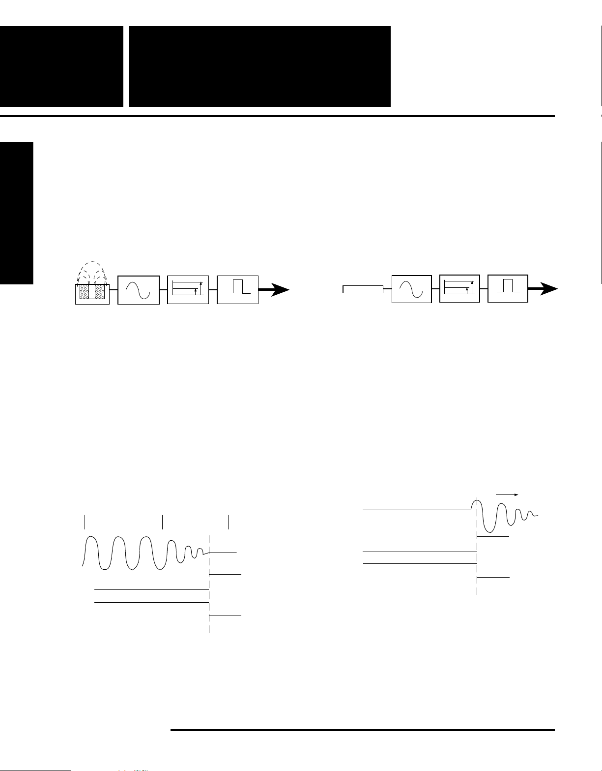
Proximity sensors are generally constructed with four main
elements: (1) a coil and ferrite core assembly; (2) an oscillator; (3) a convertor/trigger circuit (detector) and; (4) an
output device.
Proximity Sensors
TARGET
COIL OSCILLATOR DETECTOR OUTPUT
Figure 1
Capacitive
Essentially similar except that the coil is replaced by a
sensing plate, and the oscillator is not running until the
object to be detected is within range.
Figure 3
The oscillator creates a radio frequency field that is shaped
and defined by the coil and core. As a target is placed in this
field, eddy currents are set up in the surface of the target.
The oscillator, being a limited power device, will lower its
amplitude as the eddy currents are produced. The convertor/
trigger circuit rectifies the AC sine wave signal to DC,
compares the level against a preset reference, and actuates
the sensor output if a target is present. Switching is clean,
with none of the bounce of mechanical switches.
No Target Present
Normally Open
Sensor Output
Normally Closed
Sensor Output
in Sensing Field
Output non-conducting
"OFF"
Output conducting
"ON"
Target Entering
Sensing Field
Figure 2
Output conducting
"ON"
Output non-conducting
"OFF"
Capacitive sensors depend on the coupling between the
sensing plate and earth ground. If a target is placed within
range, the capacitance level will vary depending on target
density, conductivity, and relative humidity. If the adjustment
potentiometer is correctly set, the oscillator will be turned on
when a target is within range.
Target Entering
Sensing Field
Output conducting
"ON"
Output non-conducting
"OFF"
Normally Open
Sensor Output
Normally Closed
Sensor Output
No Target Present
in Sensing Field
Output non-conducting
"OFF"
Output conducting
"ON"
Figure 4
Important Note: Never use a metal body capacitive sensor in
wet environments. Moisture between the sensing plate and
the metal body will cause the sensor to “lock on.” For wet
environments, always use a plastic bodied sensor.
90
Namco • 2013 West Meeting Street • Lancaster, SC 29720 • 1-803-286-8491 • FAX: 1-800-678-6263
Page 2

Inductive Sensor Selection
1. Target Identification
This is the most critical step in proper application of inductive and capacitive sensors. Most application problems stem
from improper selection of a sensor for a particular target.
This usually comes from a desire to “standardize” a design.
Generally the following rules apply to all inductive sensors:
The sensor face should equal or be smaller than the
target surface area. All manufacturers calibrate the range
of a particular sensor with a “standard target.” This
standard target is always larger than the diameter of the
sensor face. Although it is possible to sense targets
smaller than the sensor face diameter, rated range
cannot be achieved using a target that is smaller than
the sensor face. The following changes in the sensing
range will occur if the dimensions of the target are larger
or smaller than the standard target specified.
Target 150 125 (Standard 75 50 25 12.5
size in % Target)
Deviation
from Sn in %
+10 +7 0 -7 -14 -27 -45
100
Figure 5
2. Air Gap Determination
When examining your application, remember that most
shielded inductive sensors (Fig. 6) will have a maximum
range that is approximately one third of the diameter of the
sensing face.
SHIELDED SENSOR
TARGET
METAL
SHIELD
METAL
SHIELD
It is often necessary to allow a rather large air gap between
the target and the sensor. When this is required, an
unshielded sensor (Fig. 7) will be required. The unshielded
sensor will generally have the plastic “nose” of the sensor
projecting out of the metal barrel, or (plastic bodied types) it
will not have a shielding ring around the core. These
unshielded sensors will typically sense at ranges 3 to 50
percent greater than shielded types. A penalty is paid,
however, as it is necessary to provide a metal-free area
around the sensor that is much larger than the shielded types.
NONSHIELDED SENSOR
FERRITE CORE
Figure 7
(See 3. Mounting Clearances)
Positioning of the sensor should allow the target to penetrate
approximately 30% into the field to allow for manufacturing
tolerances, resistance to vibration, and inaccuracies that are
common to all initial start-ups.
When determining the air gap (sensing distance) required, it
should be noted that an inductive sensor will produce its
rated range only against a standard target of mild steel. Other
materials will reduce the sensing range (SN) as follows:
Mild Steel SN x 1.0
Aluminum Foil SN x 1.0
Stainless Steel SN x 0.85
Brass SN x 0.5
Copper SN x 0.46
Aluminum SN x 0.4
Proximity Sensors
FERRITE CORE
Figure 6
Continued on
next page.
➟
2013 West Meeting Street • Lancaster, SC 29720
1-803-286-8491 • FAX: 1-800-678-6263
www.namcocontrols.com
For technical assistance, call 1-800-NAMTECH
91
Page 3

Reference
Proximity
Information
Sensors
Example: If a sensor with a 5mm sensing range is used to
sense a standard target made of copper, the sensing
range of the sensor is reduced as indicated below:
5mm (0.46) = 2.3mm (maximum)
When mounting a sensor it is always preferred to position the
target so that it “slides by” the sensor face. This type of
mounting will ensure that the sensor face is not damaged by
contact with the target. If your application dictates a “head on”
approach, it is essential that the target does not use the sensor
Proximity Sensors
face as a physical stop. Failure to provide clearance in either
the slide-by or head-on modes will result in damage to the
sensor and possible failure of the device.
Hysteresis (Fig. 8) must be allowed for as the target must
move far enough away from the sensing field so that the
sensor cannot detect it. If a target is placed within the hysteresis band, vibration of the target can cause the switch to turn
on and off rapidly (“chatter”). All sensor manufacturers build in
a certain amount of hysteresis to minimize chatter.
SHIELDED SENSORS
(FLUSH MOUNTABLE)
3x RANGE MIN.
DIA. (D)
UNSHIELDED SENSORS
REQUIRE METAL-FREE AREA
MINIMUM SPACING REQUIRED
D (DIAMETER OF SENSOR)
D
standard
moving direction
release point
operate point
sensing range
proximity sensor
Figure 8
target
hysteresis
3. Mounting Clearances
Mounting of sensors should follow industry accepted
practices as shown. Failure to properly position the sensor is
the single largest cause of field problems.
MINIMUM SPACING REQUIRED
2 X D (DIAMETER OF SENSOR)
DD
SENSORS MUST BE MOUNTED SUCH THAT SURROUNDING METAL
OPPOSING SENSORS
MAINTAIN 6 X RANGE
MIN. SPACING
3x RANGE MIN.
IS NOT IN THE SENSING AREA.
Figure 9
D
D
6 x RANGE
MIN.
DD
2DD
92
Namco • 2013 West Meeting Street • Lancaster, SC 29720 • 1-803-286-8491 • FAX: 1-800-678-6263
Page 4

4. Housing Selection
After you have determined the target and air gap, it is then
possible to select the style of housing for the application.
Sensors are typically grouped according to range against a
standard target. The most often used types are the metal barrel
styles. These are great for general purpose uses but should not
be used in areas where liquids are present. For wet environments, the all-plastic types are preferred. To determine your
best specific type, consult the Enclosure Types below.
Industrial Control Equipment - UL 508
Table 6.1 – Enclosure Designations
Various accessories are available for sealing, conduit, and
mounting. Also, many sensors are available with quick
disconnects. This is more expensive initially but can be
justified if the sensor is placed on moving equipment where
the cable is flexed often. The weak link then becomes the
entry point of the cable to the housing. When failure occurs,
it is necessary to replace the complete assembly because the
cable failed. It’s also easier to position the sensor mechanically, then complete the electrical wiring.
Proximity Sensors
Designation Intended Use and Description
1
2
3
3R
3S
4
Indoor use primarily to provide protection against
contact with the enclosed equipment and against a
limited amount of falling dirt.
Indoor use to provide a degree of protection
against limited amounts of falling water and dirt.
Outdoor use to provide a degree of protection
against windblown dust and windblown rain;
undamaged by the formation of ice on the
enclosure.
Outdoor use to provide a degree of protection
against falling rain; undamaged by the formation
of ice on the enclosure.
Outdoor use to provide a degree of protection
against windblown dust, windblown rain, and
sleet; external mechanisms remain operable while
ice laden.
Either indoor or outdoor use to provide a degree
of protection against falling rain, splashing water,
and hose-directed water; undamaged by the
formation of ice on the enclosure.
Designation Intended Use and Description
4X
6
6P
11
12, 12K
13
Either indoor or outdoor use to provide a degree
of protection against falling rain, splashing
water, and hose-directed water; undamaged by
the formation of ice on the enclosure; resists
corrosion.
Indoor or outdoor use to provide against the
entry of water during temporary, limited
submersion; undamaged by the formation of ice
on the enclosure.
Indoor and outdoor use to provide a degree of
protection against the entry of water during
prolonged submersion at limited depths.
Indoor use to provide by oil immersion a degree
of protection of the enclosed equipment against
the corrosion effects of corrosive liquids and
gases.
Indoor use to provide a degree of protection
against dust, dirt, fiber flyings, dripping water,
and external condensation of noncorrosive
liquids.
Indoor use to provide a degree of protection
against lint, dust seepage, external condensation, and spraying of water, oil, and noncorrosive liquids.
Table 6.1 revised December 5, 1986
©
Copyright 1977, Underwriters Laboratories Inc.
Continued on
next page.
➟
2013 West Meeting Street • Lancaster, SC 29720
1-803-286-8491 • FAX: 1-800-678-6263
www.namcocontrols.com
For technical assistance, call 1-800-NAMTECH
93
Page 5

Reference
Proximity Sensor
Information
Information
Electrical Considerations
Namco offers sensors that are suitable for direct connection
to most common types of control systems. The most
common types are listed below:
1. Relay Systems
2. Programmable Controllers
3.Custom Microprocessors
4. Output Devices (Solenoids)
Proximity Sensors
When specifying a particular output type, at no time should
the appropriate specifications of the particular sensor be
exceeded or sensor failure may result.
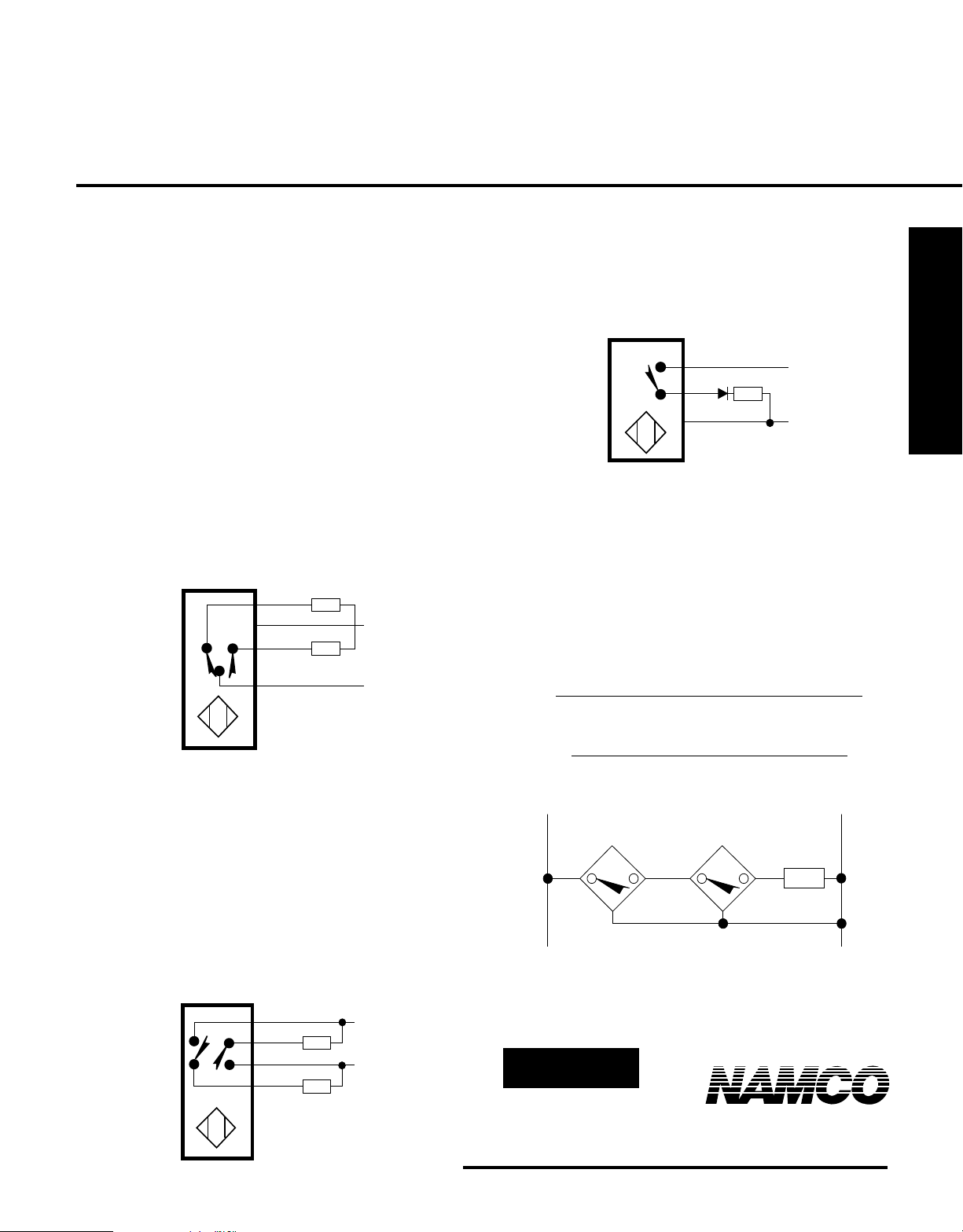
A switch in a protective interlocking circuit should be used
with at least one other device that will provide a redundant
protective function, and the circuit should be so arranged
that either device will interrupt the intended operation of the
controlled equipment. (Proposed NEMA ICS 2-225.95 std.)
RANGE vs. CURRENT
(TYPICAL)
4.0
Response Curve
3.8
3.6
3.4
3.2
3.0
2.8
I(mA)
2.6
2.4
2.2
2.0
1.8
1.6
1.4
1.2
1.0
0.8
0.6
0.4
0.2
10 20 30 40 50 60 70 80 90 100
% of Range
Namur Sensors
Namur refers to the standards committee of measurement
and control of the chemical industry of Europe. Namco
sensors comply with DIN 19234, and therefore are compatible with the Namur requirements.
This type of sensor contains only the “front end” of the
typical proximity sensor coupled to an output transistor that
will vary the current (not voltage) in proportion to the target
distance (Fig. 10). This type of sensor is normally connected
to an external amplifier which will provide the switch closure
to an external control system. It is possible to interface these
sensors to either custom external solid state relays or PLC
(Programmable Logic Control) systems with the appropriate
input card. When used with an approved intrinsically-safe
control amplifier, Namur sensors can be used in hazardous
areas. Please consult factory for application details.
When the target is not present, the sensor passes a small
amount of current (> 2.2mA). The current decreases in a
non-linear fashion as the target enters the sensing field. This
action is similar to a variable resistor. (See Figure 10.)
Figure 10
Suggested On/Off Output Circuits
for NAMUR Sensors
+7 to +9VDC
+8VDC
White
Black
White
Black
1KΩ
360Ω
4.7KΩ 2.2KΩ
100Ω
910Ω
100Ω
.1µf
+
Op-Amp
_
Load
470KΩ
Output
94
Namco • 2013 West Meeting Street • Lancaster, SC 29720 • 1-803-286-8491 • FAX: 1-800-678-6263
Page 6
DC Sensors
LOAD
BLUE
BROWN
+
_
BLACK
Available as either current sinking (NPN) or current sourcing
(PNP), this type of sensor will provide the fastest output
switching available.
The voltage range is typically 10-30 VDC with minimal drop
across the output transistor for easy connection to programmable controllers. Most DC sensors include reverse polarity
and short circuit protection as standard features.
Normally open output sensors are used in most applications.
Normally closed output sensors can be made to order.
Complimentary (one output “on,” one output “off”) output
sensors (Fig. 11) can be used as a normally open and
normally closed sensor at the same time. This convenient
sensor can be used to replace a normally open sensor or a
normally closed sensor. Simply hook up the desired output
and either tape or cut off the load lead that is not being used.
NPN (SINKING) N.O. & N.C.
WHITE NC
BROWN
BLACK NO
BLUE
Figure 11
LOAD
+
LOAD
_
When connecting DC sensors to inductive loads, it is suggested that a diode be placed in the circuit to cancel any
kickback that may damage the output of the sensor. (See
Figure 13.)
Proximity Sensors
Figure 13
Series Connection:
AND circuits can be made by series connection of
normally open output sensors.
NAND circuits can be made by series connection of
normally closed output sensors.
The maximum number of sensors that may be wired in series
is equal to the lowest number of the following two equations:
# Sensors =
Supply Voltage - Min. Operating Voltage of Load
Voltage Drop Across Each Sensor
# Sensors =
Max. Sensor Output Current - Load Current
No Load Current of Sensor
Dual output (NPN & PNP) sensors (Fig. 12) can have either
output connected to a load, or each output connected to its own
load, but not both to the same load. If the two outputs are each
connected to separate loads as shown in Figure 12, the sum
of the two load currents must not exceed the maximum load
current of sensor (typically 200mA). This particular sensor
output configuration is designed to minimize replacement
inventories. It does not have complementary switching
capabilities, i.e., both of the outputs switch either “on” or
“off” at the same time.
NPN (SINKING) & PNP (SOURCING)
BROWN
BLACK NPN
BLUE
WHITE PNP
Figure 12
+
LOAD
_
LOAD
+ –
+ +
_ _
PNP Output shown - for NPN Output reverse V
LOAD
supply
and
sensor polarities.
Continued on
next page.
➟
2013 West Meeting Street • Lancaster, SC 29720
1-803-286-8491 • FAX: 1-800-678-6263
www.namcocontrols.com
For technical assistance, call 1-800-NAMTECH
95
Page 7

Reference
Proximity
Information
In a long series string, it is possible to exceed the current
handling capacity of the last or first sensor due to the sensor
current requirements plus the load. This problem can be
circumvented by alternating types; i.e., PNP, NPN, PNP, etc.
Wiring the sensors in this manner will allow an infinite
number to be wired in series.
Parallel Connection:
Proximity Sensors
OR circuits can be made by parallel connection of
normally open output sensors.
NOR circuits can be made by parallel connection of
normally closed output sensors.
The maximum number of sensors that may be wired in
parallel is equal to the current capacity of the voltage supply
used.
+ —
Sensors
Series Connection:
Note:
Connection of more than two AC sensors in series, is
NOT recommended
AND circuits can be made by series connection of
normally open output sensors.
NAND circuits can be made by series connection of
normally closed output sensors.
The maximum number of sensors that may be wired in
series:
# Sensors =
Supply Voltage - Min. Operating Voltage of Load
Voltage Drop Across Each Sensor
LOAD
+
+
NPN Output shown - For PNP Output reverse V
sensor polarities.
—
—
and
supply
AC Sensors
AC sensors can also be connected to the same types of
control systems as the DC types but are typically load
powered. This configuration is a result of user demands for
the high reliability of solid state sensors coupled to the
requirement for minimal wiring.
In operation, the AC sensor will draw a small amount of
current through the load with no target present. This current
typically is less than 1.7mA allowing direct connection to
programmable controller input cards with no shunt resistor
required. This current must be allowed for when designing
parallel logic circuits as the leakage currents may become
large enough to actuate the load. This can be overcome by
application of a properly sized shunt resistor.
L1
LOAD
When a target is placed in the field and the sensor actuates,
the amount of voltage available to the load will be reduced by
approximately 8-10 volts. This value is critical in series
circuits. Calculations for each series circuit must be made to
ensure that enough voltage is available to actuate the load.
The same problem exists when attempting to use a two-wire
AC sensor at low AC voltages. For instance, if a 20-250 VAC
sensor is used at 24VAC, the voltage available to the load will
be between 14-18 VAC.
Parallel Connection:
OR circuits can be made by parallel connection of
normally open output sensors.
NOR circuits can be made by parallel connection of
normally closed output sensors.
The maximum number of sensors that may be wired in
parallel is
# Sensors =
Holding Current of Load
Leakage Current of Each Sensor
L2
96
Namco • 2013 West Meeting Street • Lancaster, SC 29720 • 1-803-286-8491 • FAX: 1-800-678-6263
Page 8
L1
LOAD
L2
All AC sensors have switching speeds that are much lower
than their DC counterparts. Typical switching speeds are 20
to 30 Hz.
Short circuit protection is a feature of many types of Namco
sensors. This internal circuit will protect the sensor if the
load inrush current exceeds 3 amperes. In the event of a
large inrush current, the sensor will trip into “short circuit”
mode. On standard ET/ER series sensors the LED does not
illuminate. On WFI sensors both LEDs will flash, and the
output current will be limited to approximately 2.5 mA. To
restore the sensor it is necessary to remove power for
approximately one second. The sensor will not function in
SCP mode.
The short circuit protection feature is designed to protect the
sensor and not the external circuit. The short circuit protection feature does not eliminate the need for branch circuit
fusing.
Capacitive Sensors
Capacitive sensors are unique in that they will sense most
materials including non-metallics. The actual sensing is
performed by a circuit containing an oscillator, detector
stage, and an output stage similar to the inductive type
sensor. The differences are (1) the oscillator is not running
when a target is not present, and (2) the sensing portion of
the sensor is a special plate in the sensing surface of the
sensor. This plate also has an opposing connection-to-earth
ground through the detection circuit. When an object is
placed near the sensing plate, the dielectric constant of the
material will allow coupling from the sensing plate through
the air-to-earth ground thus starting the oscillator. To
provide adjustment for the various types of materials and
their different dielectric constants, an adjustment potentiometer is typically provided.
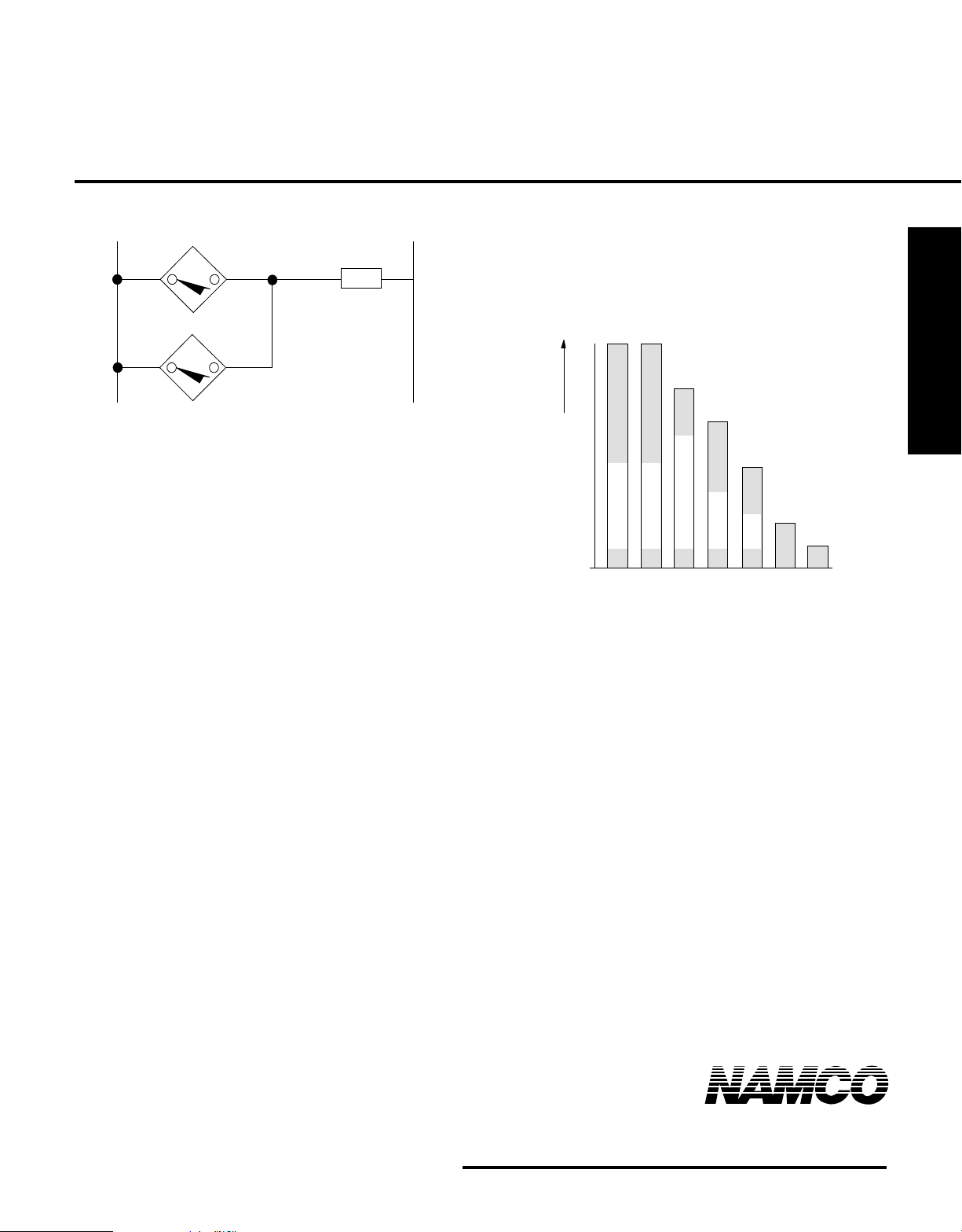
This change in dielectric constant is a requirement for
accurate sensing. If a material has a very low dielectric
constant, the sensor must be in very close proximity to the
material being sensed. Conversely, a material with a high
dielectric constant can be sensed at a greater distance.
The diagram below shows the reduction created by different
materials.
100
-
-
%
80
-
-
-
60
-
-
40
Sensing Range
20
-
-
-
0
grounded water
grounded metal
dry wood
water with no ground
glass
PVC
card board
Materials with a high dielectric constant can be sensed
through the walls of a container with a lower dielectric
constant. Example: sensing water level in a boiler sight glass
tube.
Application Cautions
1. The adjustment potentiometer is a non-linear device. Do
not attempt to adjust the sensor beyond 2/3 of the maximum
range obtained on a given material.
2. Never use a sensor with a metal housing in a damp
environment. If the face of the metal housing sensor is
splashed, the sensor will turn “On” and will not turn “Off”
until the water is removed.
3. Because the capacitive sensor depends on coupling
through the air, maximum range will be greater on hot,
humid days. It may be possible to sense a particular material
only on days when the humidity is high.
4. To determine if the material you wish to sense can be
sensed reliably, Namco recommends actual testing. If this is
not practical, consult our Applications Engineering Department.
2013 West Meeting Street • Lancaster, SC 29720
1-803-286-8491 • FAX: 1-800-678-6263
www.namcocontrols.com
Proximity Sensors
For technical assistance, call 1-800-NAMTECH
97
 Loading...