

Page 1
Reference
Limit
Information
Switches
Proper Application of Limit Switches
Limit switches are used to convert a mechanical motion
into an electrical control signal. The mechanical motion is
usually in the form of a cam, a machine component or an
object moving toward a predetermined position. The cam
engages the limit switch lever or plunger and this in turn
makes or breaks an electrical contact inside the switch. This
Limit Switches
electrical control signal is then used to limit position or
reverse the machine travel, or to initiate another operating
sequence. It can also be used for counting, sorting or as a
safety device.
Definition of Limit Switch Terms
Actuator - Mechanism of the switch or switch enclosure which
operates the contacts, i.e. lever arm, plunger, wobble stick.
General Information
Typical limit switch applications are in the control circuits
of solenoids, control relays and motor starters which control
the motion of machine tools, conveyors, hoists, elevators and
practically every type of motor driven machine.
Experience has shown that most limit switch failures are
the fault of the installation. In some cases an installation that
is not perfect cannot be avoided, but in the majority of cases,
proper application of the limit switch would have prevented
failure. For application assistance, call 1-800-NAMTECH.
force (other than gravity) is applied on the actuator. See also
“Free Position” and “Normal Position.”
Break - To open an electrical circuit.
Cam - Machine part or component that applies force to switch
actuator causing actuator to move as intended. See also “Dog.”
Cam Track - Distance from switch mounting surface to a
specified point on actuator.
Differential Travel - Distance or angle from the operating
position to the reset position.
Direct-Acting Contacts - Contacts are moved directly by the
operating shaft. In general should only be used where movement of actuator must break welded contacts, as in a crane
safety limit switch.
Dog - Machine part or component that applies force to switch
actuator causing actuator to move as intended. See also “Cam.”
Double Break - Contacts open circuit at two points.
Double Pole Double Throw (DPDT) - Switches which make and
break two separate circuits. This circuit provides a normally
open and normally closed contact for each pole.
Free Position - Position of switch actuator when no external
force (other than gravity) is applied on the actuator. See also
“Initial Position” and “Normal Position.”
Maintained Contact Switch - Designed for applications
requiring sustained contact after actuator has been released,
but with provision for resetting.
Make - To close or establish an electrical circuit.
Momentary Contact Switch - A switch which returns from the
operated condition to normal condition when actuating force
is removed. See also “Spring Return.”
Neutral Position Limit Switch - Lever arm type switch with
two sets of contacts, one of which operates when the shaft is
rotated clockwise and the other of which operates when the
shaft is rotated counter-clockwise.
Normal Position - Position of switch actuator when no
external force (other than gravity) is applied to actuator. See
also “Free Position” and “Initial Position.”
Normally Closed Contact (N.C.) - Contacts that move to the
closed position when no external force is on the actuator.
Normally Open Contacts (N.O.) - Contacts that move to the
open position when no external force is on the actuator.
Operating Force - Amount of force applied to the actuator to
cause contact operation.
Initial Position - Position of switch actuator when no external
302
Namco • 2013 West Meeting Street • Lancaster, SC 29720 • 1-803-286-8491 • FAX: 1-800-678-6263
Page 2
Operating Position - Position of the actuator at which the
contacts move to the operated position. See also “Trip
Position.”
Overtravel - Movement of the actuator beyond the operating
position.
Pilot Duty Rating - Rating of contacts when making and
breaking inductive loads such as coil and solenoids.
Pole - Parts necessary to control one conductor of a circuit.
Precision Snap Acting Switch - An electromechanical switch
having predetermined and accurately controlled characteristics and having a spring loaded, quick make-and-break
contact action.
Pretravel - Distance or angle through which the actuator
moves from the normal position to the operating position.
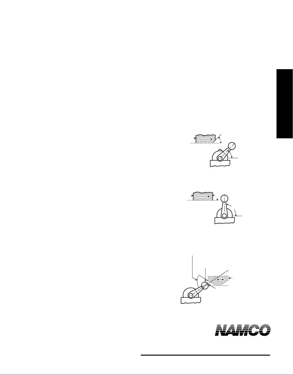
A good recommended cam angle and lever arm angle at
moderate cam speeds (up to 90 fpm) is 45°, see Figure 1-1.
Here lever acceleration is less and deceleration is also less at
the lower cam edge.
The arrangement shown in Figure 1-2 is satisfactory only
at cam speeds below 50 fpm. At higher speeds, the impact
due to high lever acceleration causes excess roller bounce.
Rapid deceleration occurs at the lower cam edge.
The cam trailing edge on overriding cams must also be
considered for maximum switch life, see Figure 1-3. Lever
arm snap back causes shock loads which reduce switch life.
Also, with reversing cams the trailing edge becomes a leading
edge on the return stroke.
Reset Position - Position of actuator at which contacts return
to the normal position. See also “Releasing Position.”
Releasing Position - Position of actuator at which contacts
return to the normal position. See also “Reset Position.”
Repeat Accuracy - Ability of a switch to repeat its characteristics precisely from one operation to the next operation. See
also “Repeatability.”
Repeatability - Ability of a switch to repeat its characteristics
precisely from one operation to the next operation. See also
“Repeat Accuracy.”
Single Pole Double Throw (SPDT) - Switches which make
and break one circuit. Circuit provides one normally open and
one normally closed contact.
Slow Make-and-Break Contacts - The speed of contact
transfer is directly dependent on the speed of the operating
shaft.
Snap Action - Rapid motion of the contacts from one position
to another position or their return. This action is relatively
independent of the rate of travel of the actuator.
Snap Back - Sudden return of actuator to normal position.
Spring Return Switch - A switch which returns from operated
condition to normal condition when actuating force is
removed. See also “Momentary Contact Switch.”
Trip Position - Position of the actuator at which the contacts
move to the operated position. See also “Operating Position.”
Total Travel - Distance from actuator-free position to overtravel limit position.
Actuator Design
For maximum limit switch life, the force applied to the
lever arm by a cam should be perpendicular to the lever arm.
This means that the cam angle and lever arm angle should be
the same.
CAM
Recommended for moderate cam speeds - up to 90 fpm
CAM
Satisfactory only for low cam speeds - 50 fpm or less
60˚ Max. - Reversing Cam
80˚ Max. - Non-reversing Cam
For overriding cams - up to 90 fpm
Figure 1.1
Non-overriding cams
Figure 1.2
Non-overriding cams
Top of Roller Should
Be Not Less Than 1/8
Below End of Cam
Figure 1.3
2013 West Meeting Street • Lancaster, SC 29720
45˚
45˚
90˚
90˚
Lever Arm
Initial Position
Cam
Do Not Contact Roller
Within Shaded Areas
Do Not Allow Lever Arm
to Snap Back
1-803-286-8491 • FAX: 1-800-678-6263
www.namcocontrols.com
Limit Switches
For technical assistance, call 1-800-NAMTECH
303
Page 3
Reference
Limit
Information
Switches
Electrical Ratings
RATINGS —
Many control applications involve high inductive loads such
as starter, contactor and relay coils; solenoids and clutches.
In order to apply a control device correctly, the inductive
rating must be known. Ratings are generally listed in three
ways:
Limit Switches
1. Resistive or non-inductive.
2. Inductive (pilot duty).
3. Continuous.
Resistive or non-inductive ratings - This rating indicates the
resistive load only that the contacts make or break. Resistive
ratings are generally based on a 75% minimum power factor
for AC.
Inductive (pilot duty) ratings - The inductive rating indicates
the non-motor inductive load, such as the contactors, relays
and other remotely controlled devices that the contacts can
make or break. These ratings usually are based on a 35%
power factor for AC.
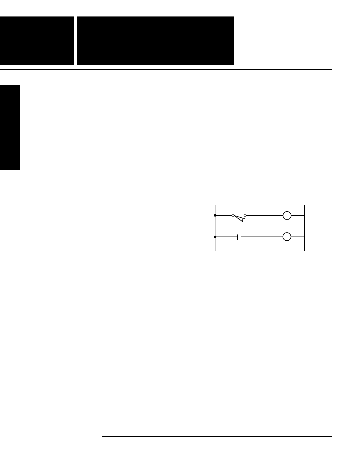
Excessive load - If the load exceeds the ratings of the limit
switch being used, a control relay (CR) or contactor with
proper ratings can be used as in Figure 1-4.
The DC current ratings of a device can be increased by
placing contacts in series. This effectively increases the
contact gap allowing a higher current rating. In general, the
following ratings can be applied:
2 contacts in series — DC rating x 2.5
3 contacts in series — DC rating x 5
Current should never exceed the maximum continuous
current rating of the device.
L1 L2
CR
CR
M
Continuous rating - Continuous rating indicates the load that
the contacts can carry continuously without making or
breaking the circuit.
The inductive rating is always less than the resistive or
continuous rating. When contacts break an inductive circuit,
the inductance in the load tends to keep the current flowing in
the same direction. The result is an arc across the contacts
which causes heating and burning of the contacts. Because of
the extra heat generated, the allowable inductive current must
be less than the resistive current for equal contact life.
Quick make and quick break (snap-action) contacts
reduce the arcing time and allow higher inductive ratings than
with slow make-or-break contacts. AC inductive coil loads
have a momentary inrush current of approximately 10 times
the sealed current. Contacts must be able to break or interrupt
the inrush current in an emergency.
Figure 1.4
304
Namco • 2013 West Meeting Street • Lancaster, SC 29720 • 1-803-286-8491 • FAX: 1-800-678-6263
Page 4
Contact Resistance
RESISTANCE OF SNAP SWITCHES
Snap switch resistance is the total electrical resistance that a
snap switch adds to the circuit and consists of:
Conducting Path. Includes all terminals, inserts, station-
ary contact material resistance, movable contact material
resistance, movable blade assembly, and any other parts
in the conducting circuit.
Constriction Resistance of all joints, discontinuities, or
interfaces. This is the resistance caused by limited
mating surfaces through which the load must pass. If the
movable and stationary contact tips are viewed through a
microscope, it can be seen that they only touch at a very
few points. Thus, increased resistance is presented to the
current. If the current is high enough, the points of
constriction are softened and enlarged through thermal
effects and the resistance decreases.
Film resistance. It is well known that silver accumulates
a surface resistance due to chemical reaction with its
environment. The most common reaction is with sulfur
and oxygen which creates a sulfide and an oxide of silver.
Such a surface is known to have some resistance which
can be read with a low voltage instrument such as an
ohmmeter. These surfaces, however, have the character-
istic of being self-clearing. When current is passed
through such a surface, it creates heat which, in turn,
reduces the compound to pure silver again and restores
the contact to a low ohmic value. This has long been the
characteristic which has made silver such a good
selection for contact materials.
Standard contacts can be gold plated to reduce switch
resistance, but may not provide sufficient increase in reliability to warrant the added cost. For example, if the contact
material underneath is exposed at any point due to excessive
current or normal mechanical wear, a contaminating film may
develop and will eventually creep over the plated portion.
Long-term reliability is then no better than with standard
contacts.
Particle resistance. Contamination in the form of foreign
material can also produce resistance. Carefully controlled
production processes are used to prevent contamination
during assembly of snap switches.
control equipment where voltages are relatively high —
normally 120 volts or higher — and current levels are high —
normally .25 amperes or higher. An increase in switch
resistance may appear to be more critical in high energy
circuits because it represents a greater percentage of total
circuit impedance; however, the arcing produced breaks down
or burns away the contaminants, reducing the actual resistance seen by the load.
Switch resistance in dry circuit (low voltage, low current)
applications is more of a problem, but the resistance has to
be quite high to significantly affect operation. For example, a
solid state circuit operating at 20 volts and 1 ma has a circuit
resistance of 20 divided by (1 x 10⁻³) or 20,000 ohms. A
Snap-Lock switch with 10 ohms resistance would have little
effect. The problem arises with film or particle resistance
which can be quite high or even present an open circuit. Use
of snap switches with dry circuits is not recommended
because these voltages and currents are not high enough to
reduce the silver sulfide or silver oxide to pure silver or to
burn away other contaminants present.
An ohmmeter test on Snap-Lock switches is unreliable
because the most common voltage source in an ohmmeter is
a 1.5 volt battery and to snap switch contacts being tested,
this is just another dry circuit load. Several ohmmeter
readings of the same contacts may vary from a few hundredths of an ohm to several ohms, yet the contacts will work
perfectly with a nominal coil load.
Recommendations for Application and Testing of Limit
Switch Contacts
Standard Namco limit switches are normally recommended
for use with industrial control devices, not dry circuits. If
lower voltages are present, the current drawn through the
contacts should be on order of .25 amperes in order to
maintain proper continuity.
To test continuity in the field, a six volt, .25 ampere pilot
light is recommended.
Do not use an ohmmeter to test continuity.
An ohmmeter is a reliable test only if the snap switch is
to be used with a dry circuit and, as stated above, this is
normally not recommended.
Limit Switches
Namco limit switches are designed for use with industrial
2013 West Meeting Street • Lancaster, SC 29720
1-803-286-8491 • FAX: 1-800-678-6263
www.namcocontrols.com
For technical assistance, call 1-800-NAMTECH
305
Page 5
Reference
Limit
Information
Wiring and Mounting
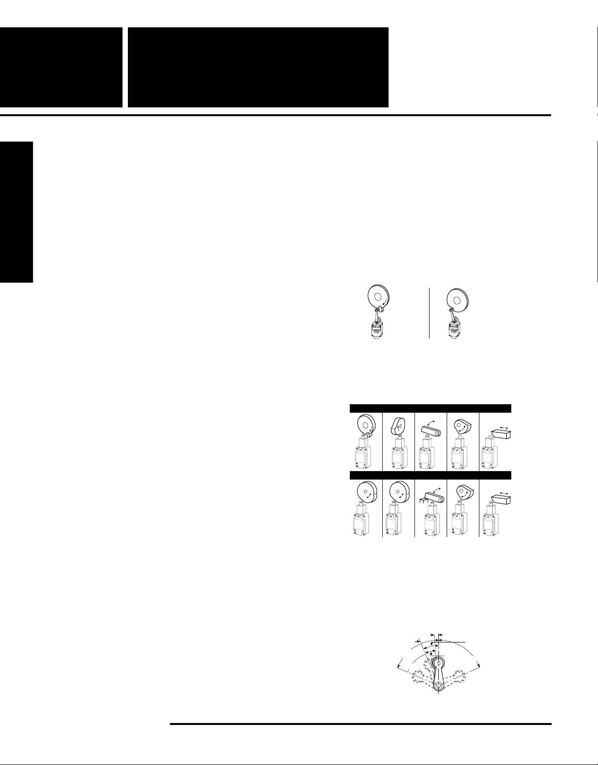
• Unless specifically designed for such service, limit
switches SHOULD NOT BE submerged in or splashed
with oils, coolants or other liquids. CONSULT FACTORY.
• Limit switches MUST NOT BE used in locations where
temperature or atmospheric conditions are beyond
those for which they have been specifically designed.
Limit Switches
• Power from different sources MUST NOT BE connected
to the contact of one limit switch unless specifically
designed for such service.
• Limit switches MUST BE used within their contact
ratings. Refer to switch label on cover for electrical
ratings and the appropriate limit switch bulletin for
acceptable environmental conditions in which the switch
has been designed to function properly.
• Limit switches SHOULD BE mounted rigidly and in
readily accessible locations, with suitable clearances to
permit easy service and replacement when necessary.
Cover plates SHOULD face the maintenance access
point.
• Limit switches SHOULD BE placed in locations where
machining chips do not accumulate under normal
operating conditions to avoid chip interference with the
lever operation.
Switches
Actuator Consideration
• Where relatively slow motions operate the limit switch, a
snap-acting or snap-lock design SHOULD BE used.
• Where relatively fast motions are involved, cam arrangement SHOULD BE such that the actuator does not
receive a severe impact.
• Where relatively fast motions are involved, cams MUST
BE designed such that the limit switch will be held
operated long enough to operate relays, valves, etc.
Wrong Right
Fast
Motion
LIMIT SWITCH
EA
• For limit switches with pushrod actuators, the actuating
force SHOULD BE applied as nearly as possible in line
with the pushrod axis.
Wrong
Fast
Motion
LIMIT SWITCH
EA
• Opposite polarities MUST NOT BE connected to the
contacts of one limit switch unless the limit switch is
specifically designed for such service.
Limit Switch Selection
Selection of the proper electro-mechanical limit switch for an
application generally breaks down into two major decisions,
choosing the proper actuator (lever) and choosing the proper
enclosure. There are other considerations, such as what
operating sequences are available, temperature rating and
electrical rating. These vary from switch type to switch type.
Selection of Limit Switch Actuator — Selection of a
suitable actuator depends on the shape, speed, direction and
total travel of the cam or part being used to trip the limit
switch and the accuracy desired. See Operating Levers
Section for levers offered fitting Namco limit switches.
306
Right
Stop
• Limit switches MUST NOT BE operated beyond the
manufacturer’s recommended travel. Operating positions and lever travel terminology are illustrated in
drawing below. For specifications of a specific switch,
refer to the switch bulletin.
Reset Position
Trip Position
Total
Travel
Overtravel
Namco • 2013 West Meeting Street • Lancaster, SC 29720 • 1-803-286-8491 • FAX: 1-800-678-6263
Initial Position
Trip
Travel
Reset
Travel
Over Travel
Page 6
NOTE: When loosening or tightening the pipe plug or set
screw used to clamp the actuating lever in the desired
position, care must be exercised to restrain the shaft/
lever assembly so as not to transmit the applied torque
to the switch itself.
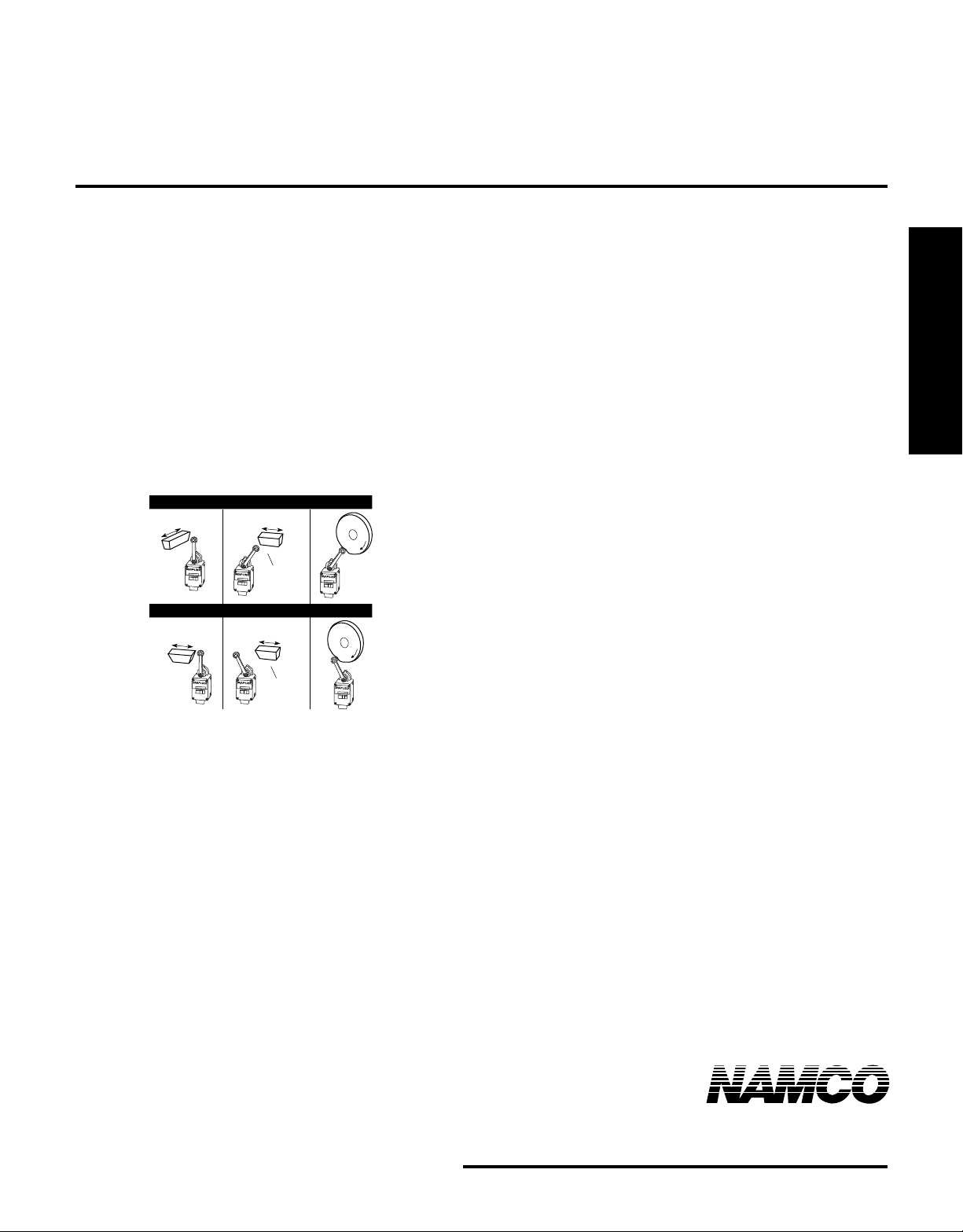
• Cam or dog arrangements SHOULD BE such that the
actuator is not suddenly released to snap back freely
unless specifically designed for such service.
• For limit switches with lever actuators, the actuating
force SHOULD BE applied as nearly perpendicular to the
lever as practical and perpendicular to the shaft axis in
which the lever rotates.
Wrong
Limit Switches
LIMIT SWITCH
EA
LIMIT SWITCH
EA
LIMIT SWITCH
EA
LIMIT SWITCH
EA
Right
NonOverriding
Cam
NonOverriding
Cam
LIMIT SWITCH
EA
LIMIT SWITCH
EA
• A limit switch actuator MUST BE allowed to move far
enough for positive operation of the contacts.
• Limit switches MUST BE mounted in locations which
will prevent false operation by normal movements of
operator or machine components.
• Limit switches are designed for proper performance
with the actuators with which they are supplied.
Supplementary actuators SHOULD NOT BE used unless
the limit switches are specifically designed for them.
• Operating mechanisms for limit switches MUST BE so
designed that, under any operating or emergency
conditions, the limit switch is not operated beyond its
overtravel limit position. A limit switch MUST NOT BE
used as a mechanical stop.
2013 West Meeting Street • Lancaster, SC 29720
1-803-286-8491 • FAX: 1-800-678-6263
www.namcocontrols.com
For technical assistance, call 1-800-NAMTECH
307
Page 7
Reference
Limit
Information
Switches
Cam Design
The most important consideration in the proper application of
limit switches is external cam design. The majority of limit
switch failures can be traced to poor cam design. Excessive
overtravel and/or excessive snap back of the operating lever
arm are the most common abuses. Good cam design will
greatly increase the life of a limit switch.
Limit Switches
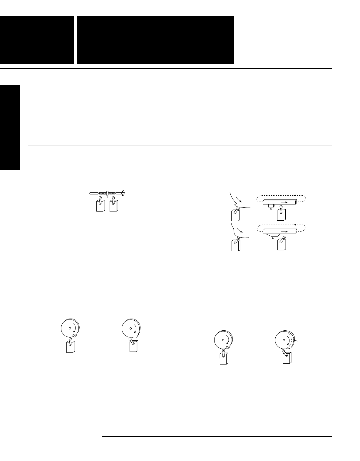
ICS2-225.83 - Where relatively slow motions
operate the limit switch, it should
generally be snap acting.
Slow
Motion
Listed below are general rules for the proper design and
application of limit switch cams published by NEMA in
Standards Publication ICS2-225.
ICS2-225.85 - Cam or dog arrangements should be
such that the actuator is not suddenly
released to snap back freely.
Wrong
(Overriding
Cam)
ICS2-225.84 - Where relatively fast motions are
involved, cam arrangements should be
such that the actuator does not receive
a severe impact
Fast
Motion
Wrong Right
Right
ICS2-225.86 - Where relatively fast motions are
involved, cams should be designed
such that the limit switch will be held
operated long enough to operate
relays, valves, etc.
Wrong Right
(Overriding
Cam)
Dwell
308
Namco • 2013 West Meeting Street • Lancaster, SC 29720 • 1-803-286-8491 • FAX: 1-800-678-6263
Page 8
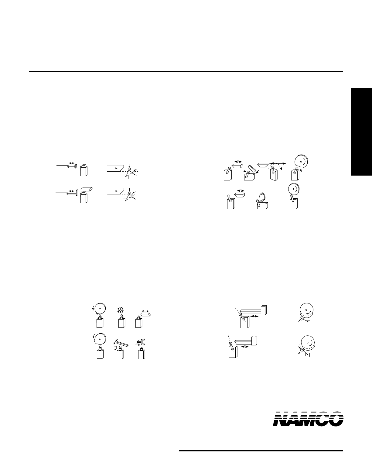
ICS2-225.88 - Operating mechanisms for limit
switches should be so designed that
under any operating or emergency
conditions, the limit switch is not
operated beyond its overtravel limit
position. A limit switch should not be
used as a mechanical stop.
Free Position
Wrong
Right
Wrong
Stop
Right
Interference
End of
Overtravel
Free Position
Operated
Position
End of
Overtravel
ICS2-225.90 - For limit switches with lever actuators,
the actuating force should be applied
as nearly perpendicular to the lever as
practical, and perpendicular to the
shaft axis about which the lever
rotates.
Wrong
Now
Over-Riding
Right
Limit Switches
ICS2-225.89 - For limit switches with pushrod
actuators, the actuating force should
be applied as nearly as possible in line
with the push rod axis.
Wrong
Right
Stop
Stop
ICS2-225.91 - A limit switch actuator must be
allowed to move far enough for
positive operation of the contacts.
Roller Arm Reset
or Releasing
Position
Cam
Right
Stop
Cam
Wrong
Stop
Wrong
Operating
Position
Right
Operating Position
Operated Position
2013 West Meeting Street • Lancaster, SC 29720
1-803-286-8491 • FAX: 1-800-678-6263
www.namcocontrols.com
For technical assistance, call 1-800-NAMTECH
309
Page 9
Reference
Limit
UL
Information
UL Listing of Namco Switches
The following is a list of all switches which are listed with Underwriters Laboratories:
File: E12967 Special Use Switches
Switch Marking: Underwriters Laboratory Inc. Recognized Snap Switch
Limit Switches
Listed Switches: EA700-10000, -10001, -10100, -40000, -40001, -40100, -70000, -70001, -70100, -20000, -
File: E23331, Snap Switches for Use in Hazardous Locations
Switch Marking: Listed 921M
Listed Switches: EA800-10040, -10050, -10060, -10944, -10954, -10964, -20040, -20050, -20060, -20944, -
Switches
20001, -20100, -50000, -50001, 50100, -80000, -80001, -80100, -30000, -30001, -30100, 60000, -60001, -60100, -90000, -90001, -90100
20954, -20964, -30040, -30050, -30060, -30944, -30954, -30964
Listings
File: E59180, Industrial Control Equipment, Auxiliary Devices
Switch Marking: Listed Industrial Control EQ145M
Listed Switches: EA040-11105, EA040-21105, EA060-11105, EA060-21105, EA080-11105, EA080-21105
File: E62691, Industrial Control Equipment, Auxiliary Devices for use in Hazardous Locations
Switch Marking: Listed Industrial Control EQ for Haz Loc 727U
Listed Switches: EA880-11100, -11200, -11500, -11600, -12100, -12200, -12500, -12600, -13100, -13200, -
13500, -13600
As presently produced, the EA170 and EA180 switches are not listed.
310
Namco • 2013 West Meeting Street • Lancaster, SC 29720 • 1-803-286-8491 • FAX: 1-800-678-6263
Page 10
Reference
Limit
NEMA
Information
Switches
ICS 6-110.01 Definitions
Acid-resistant - Acid-resistant means so constructed that it
will not be injured readily by exposure to acid fumes.
Dripproof - Dripproof means so constructed or protected that
falling dirt or drops of liquid will not interfere with the
successful operation of the apparatus under specified test
conditions. See ICS 6-110.52.
Driptight - Driptight means so constructed or protected as to
exclude falling dirt or drops of liquid under specified test
conditions. See ICS 6-110.52.
Dusttight - Dusttight means so constructed as to meet the
requirements of a specified dusttightness test. See ICS 6-
110.54.
External Mounting - External mounting means enclosure
mounting provisions external to the apparatus cavity.
Flush Mounting - Flush mounting means so designed as to
have a minimal front projection when set into and secured to
a flat surface.
Knockout - A knockout is a portion of the wall of a box or
cabinet so fashioned that it may be removed readily by a
hammer, screwdriver, and pliers at the time of installation in
order to provide a hole for the attachment of a raceway cable
or fitting.
Hazardous Locations - Hazardous locations are those areas
which may contain hazardous materials in sufficient quantity
to create an explosion. See Article 50 of the National Electrical
Code.
Nonventilated - Nonventilated means so constructed as to
provide no intentional circulation of external air through the
enclosure.
NEMA Standard 12-8-1972.
NEMA Standard 7-16-1969.
NEMA Standard 7-16-1969.
NEMA Standard 7-16-1969.
NEMA Standard 7-16-1969.
NEMA Standard 7-16-1969.
NEMA Standard 7-16-1969.
NEMA Standard 7-16-1969.
NEMA Standard 7-16-1969.
Definitions
Rainproof - Rainproof means so constructed, protected or
treated as to prevent rain under specified test conditions from
interfering with successful operation of the apparatus. See
ICS 6-110.53.
NEMA Standard 7-16-1969.
Raintight - Raintight means so constructed or protected as to
exclude rain under specified test conditions. See ICS 6-110.53
NEMA Standard 7-16-1969.
Resistant (Used as a Suffix) - Resistant (used as a suffix)
means so constructed, protected, or treated that the apparatus will not be damaged when subjected to the specified
material or conditions for a specified time.
NEMA Standard 7-16-1969.
Sleetproof - Sleetproof means so constructed or protected
that the accumulation of sleet (ice) under specified test
conditions will not interfere with the successful operation of
the apparatus including external operating mechanism(s). See
ICS 6-110.55.
NEMA Standard 7-16-1969.
Sleet-resistant - Sleet-resistant means so constructed that
the accumulation and melting of sleet (ice) under specified
test conditions will not damage the apparatus. See ICS 6-
110.55.
NEMA Standard 7-16-1969.
Submersible - Submersible means so constructed as to
exclude water when submerged in water under specified test
conditions of pressure and time.
NEMA Standard 7-16-1969.
Tight (Used as a Suffix) - Tight (used as a suffix) means so
constructed that the enclosure will exclude the specified
material under specified conditions.
NEMA Standard 7-16-1969.
Watertight - Watertight means so constructed as to exclude
water applied in the form of a hose stream under specified
test conditions. See ICS 6-110.56.
NEMA Standard 7-16-1969.
Limit Switches
Outdoor - Outdoor means suitable for installation where
exposed to the weather.
NEMA Standard 7-16-1969.
Proof (Used as a Suffix) - Proof (used as a suffix) means so
constructed, protected or treated that successful operation of
the apparatus is not interfered with when subjected to the
specified material or condition.
NEMA Standard 7-16-1969.
2013 West Meeting Street • Lancaster, SC 29720
1-803-286-8491 • FAX: 1-800-678-6263
www.namcocontrols.com
For technical assistance, call 1-800-NAMTECH
311
 Loading...