

NAMCO Bandai Games EA530 User Manual
EA530 Series Compact Limit SwitchesProduct Instructions
Publication #
EAIS02
IMPORTANT
Instructions for proper applications and uses of
COMPACT LIMIT SWITCHES
EXPERIENCE HAS SHOWN THAT THE MECHANICAL
AND ELECTRICAL OPERATING LIFE OF A LIMIT
SWITCH IS INFLUENCED TO A LARGE DEGREE BY
PROPER INSTALLATION AND APPLICATION
PROCEDURES. THIS PUBLICATION IS INTENDED TO
BE USED AS A GUIDE.
Wiring and Mounting:
• Unless specifically designed for such service limit switches
SHOULD NOT BE submerged in or splashed with oils,
coolant or other liquids. CONSULT FACTORY.
• Limit switches MUST NOT BE used in locations where
temperature or atmospheric conditions are beyond those for
which they have been specifically designed.
• Power from different sources MUST NOT BE connected to
the contacts of one limit switch unless specifically designed
for such service.
• Limit switches MUST BE used within their contact ratings
and the appropriate limits switch bulletin for acceptable
environmental conditions in which the switch has been
designed to function properly.
• Limit switches SHOULD BE mounted rigidly and in readily
accessible locations, with suitable clearances to permit
easy service and replacement when necessary. Cover
plates SHOULD face the maintenance access point.
• Limit switches SHOULD BE placed in locations where
machining chips do not accumulate under normal operating
conditions to avoid chip interference with the lever
operation.
• Opposite polarities MUST NOT BE connected to the
contacts of one limit switch unless the limit switch is
specifically designed for such service.
A SWITCH IN A PROTECTIVE INTERLOCKING CIRCUIT SHOULD BE
WARNING:
USED WITH AT LEAST ONE OTHER DEVICE THAT WILL PROVIDE A
REDUNDANT PROTECTIVE FUNCTION, AND THE CIRCUIT SHOULD
BE SO ARRANGED THAT EITHER DEVICE WILL INTERRUPT THE
INTENDED OPERATION OF THE CONTROLLED EQUIPMENT.
(PROPOSED NEMA ICS 2-225.95 St'd.)
SERVICING ENERGIZED INDUSTRIAL CONTROL EQUIPMENT CAN
BE HAZARDOUS. SEVERE INJURY OR DEATH CAN RESULT FROM
ELECTRICAL SHOCK, BURN OR UNINTENDED ACTUATION OF
CONTROLLED EQUIPMENT.
RECOMMENDED PRACTICE IS TO DISCONNECT AND LOCK OUT
CONTROL EQUIPMENT FROM POWER SOURCES, AND
DISCHARGE STORED ENERGY IN CAPACITORS, IF PRESENT. IF IT
IS NECESSARY TO WORK IN THE VICINITY OF ENERGIZED
EQUIPMENT, ONLY QUALIFIED PERSONNEL SHOULD BE
PERMITTED TO PERFORM SUCH WORK , USING ALL APPLICABLE
SAFETY PRACTICES AND PROTECTIVE EQUIPMENT.
IMPORTANT: MAINTENANCE NOTE
LOW AND HIGH TEMPERATURE LIMIT SWITCHES ARE
MANUFACTURED USING SPECIAL MATERIALS AND
COMPONENTS NOT AVAILABLE AS MAINTENANCE KITS
FROM THE FACTORY. DISCARD DAMAGED OR WORN
LIMIT SWITCHES AND REPLACE WITH NEW SWITCHES
FROM THE FACTORY.
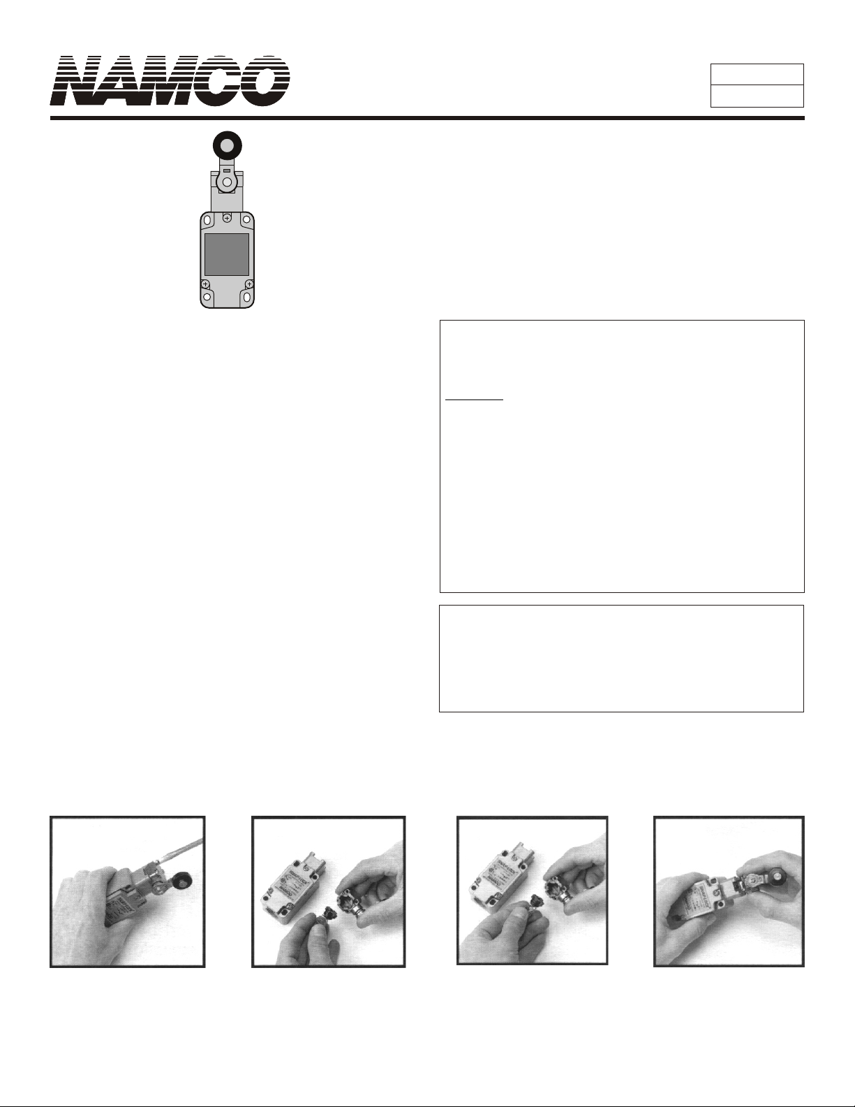
Head Rotation Procedure
STEP 1
Remove 4 top screws.
Remove spring and plunger
(Mechanism is spring-loaded.
Watch out for parts.)
* Rotating it clockwise 90° makes it a clockwise-only switch. Rotating it counter-clockwise makes it a counter-clockwise-only switch.
(Switch operates both directions when shipped).
STEP 2 STEP 3 STEP 4
Note orientation of plunger
assembly from head.
assembly*
Re-assemble.
EA530 Series Compact Snap-Lock Limit Switch
Product Instructions
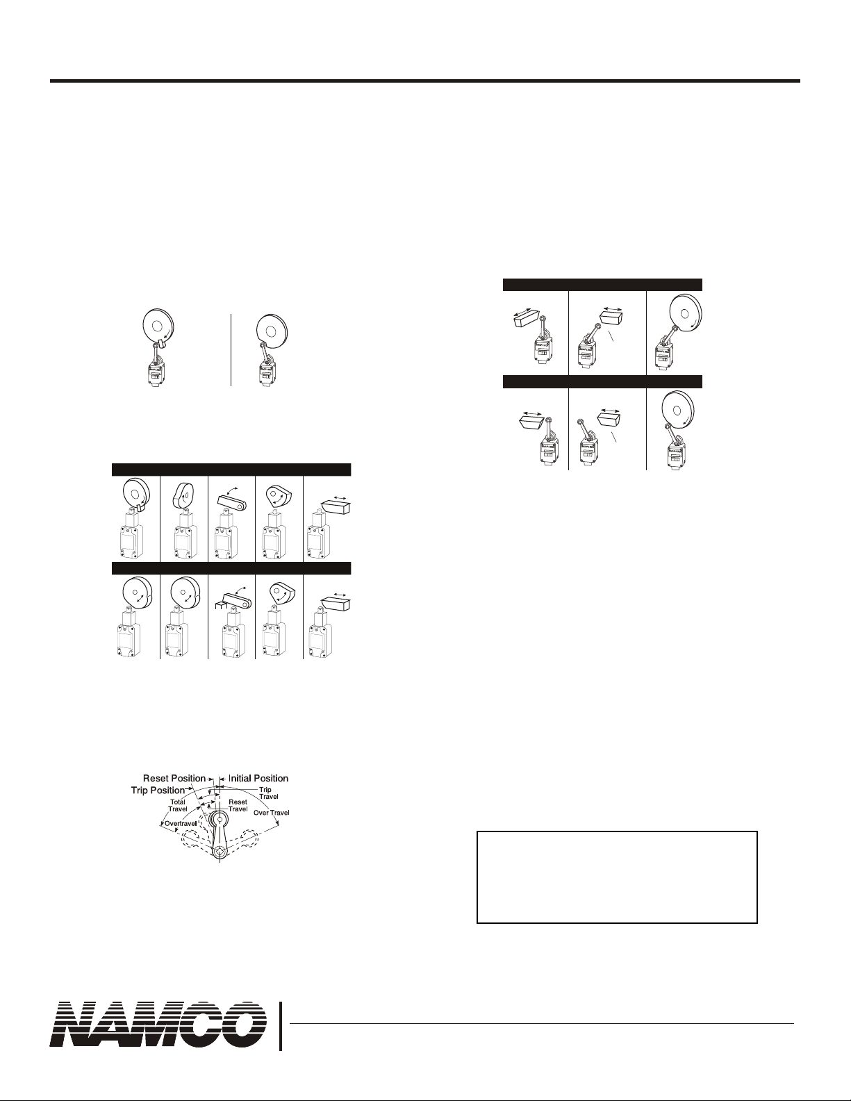
Actuator Consideration
Where relatively slow motions operate the limit switch, a
snap-acting or snap-lock design SHOULD BE used.
Where relatively fast motions are involved, cam
arrangement SHOULD BE such that the actuator does not
receive a severe impact.
Where relatively fast motions are involved, cams MUST BE
designed such that the limit switch will be held operated long
enough to operate relays, valves, etc.
Wrong Right
Fast
Motion
LIMIT SWITCH
EA
For limit switches with pushrod actuators, the actuating
force SHOULD BE applied as nearly as possible in line
with the pushrod axis.
Wrong
LIMIT SWITCH
EA
Fast
Motion
Cam or dog arrangements SHOULD BE such that the
actuator is not suddenly released to snap back freely
unless specifically designed for such service.
For limit switches with lever actuators, the actuating force
SHOULD BE applied as nearly perpendicular to the lever
as practical and perpendicular to the shaft axis in which
the lever rotates.
Wrong
LIMIT SWITCH
EA
LIMIT SWITCHEALIMIT SWITCH
LIMIT SWITCH
EA
EA
Right
NonOverriding
Cam
NonOverriding
Cam
LIMIT SWITCH
EA
LIMIT SWITCH
EA
A limit switch actuator MUST BE allowed to move far
enough for positive operation of the contacts.
Right
Stop
Limit switches MUST NOT BE operated beyond the
manufacturer's recommended travel. Operating positions
and lever travel terminology are illustrated in drawing
below. For specifications of a specific switch, refer to the
switch bulletin.
NOTE: When loosening or tightening the pipe plug or set
screw used to clamp the actuating lever in the desired
position, care must be exercised to restrain the shaft/lever
assembly so as not to transmit the applied torque to the
switch itself.
Limit switches MUST BE mounted in locations which will
prevent false operation by normal movements of operator
or machine components.
Limit switches are designed for proper performance with
the actuators with which they are supplied.
Supplementary actuators SHOULD NOT BE used unless
the limit switches are specifically designed for them.
Operating mechanisms for limit switches MUST BE so
designed that, under any operating or emergency
conditions, the limit switch is not operated beyond its
overtravel limit position. A limit switch MUST NOT BE used
as a mechanical stop.
The user should refer to NFPA 70B,
RECOMMENDED PRACTICE FOR
ELECTRICAL MAINTENANCE, published
by the National Fire Protection
Association, for additional information.
2013 West Meeting Street • Lancaster, SC 29720 • Technical Assistance: 1-800-NAMTECH
GmbH • Mittelfeld 10 • D-25379 Herzhorn • Tel +49-4124-9359 0 • Fax +49-4124-9359 15
© 2002 Namco | www.namcocontrols.com | 7/02 | EAIS02-D (IO530-10010)
 Loading...