

Nakamichi 700 Owners manual

Nakamichi
700
3 Head Cassette Deck
Operating Instructions

We thank you very much for your purchase
of the Nakamichi 700.
This recorder is designed especially for the
most critical audiophile and maintains
almost same high performance as the
Nakamichi 1000.
Before using this recorder please read this
instruction manual very carefully so that
all functions and features will fully be used
with the highest performance.
Contents:
Control Functions............. 1/2
Connection ................. 3
Playback Procedures
Before Recording ............. 5
Level Calibration
Recommended Cassette Tapes and
Tape Selector
Record Procedures
Additional Recording and
Playback Techniques
Peak
Level dB Meter
Dolby Noise Reduction System ... 11
Trouble
Specifications.
Optional
Shooting
Accessories
...........
.............
Switch
............
............
...........
...........
Chart
.........
...............
...........
4
6
7
8
9
10
12
13
13
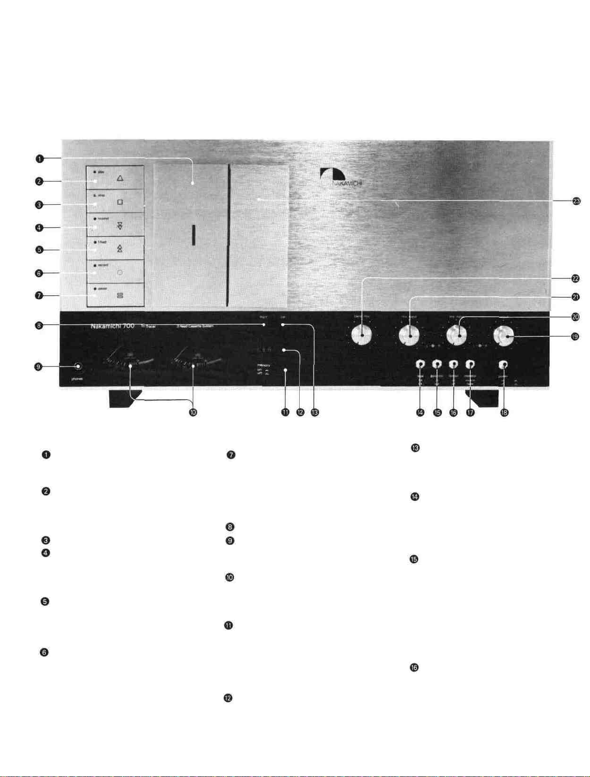
Control Functions
Cassette Lid:
The Lid will open when the Eject Button is
pushed.
Playback Button:
Tape runs at the standard speed and when
the button is pressed, playback of the
pre-recorded tapes will commence.
Stop Button
Rewind Button:
Causes tape to move rapidly from left to
right
reel.
Press
the
"Stop"
auto-stop to function.
button
or allow
Fast Forward Button:
Causes tape to move rapidly from right to
left reel. When tape reaches the end, press
the "Stop" or allow auto-stop function.
Record Button:
Recording will be commenced when pushed
simultaneously with the "PLAY" Button.
Pause Button:
Used to momentarily stop the tape in
recording or playback mode. During
recording, the recording circuits remain
operative, and capstan remains in motion but
pinch roller is retracted.
Eject Button
Headphone Jack:
The headphones should have an impedance
of 8 ohm.
Peak Level Meters:
The Meters indicate a wide range from —40
dB to +5 dB, the 0 dB of which conforms to
the Dolby NR Standard Level.
Tape Start Memory Switch:
If you set the tape counter to "000" at the
start of each recording, and set the Memory
Switch to "ON" then the tape will be
rewound at the touch of the Rewind Button
to the preset point and will stop.
Index Tape Counter
Adjustment Lid Button:
When the Lid is opened, you will find the
adjustment functions for Azimuth
Alignment, Test Tone, and Pitch Control.
Tape Selector Switch:
Set to "EX" for Nakamichi EX, EX 11
tapes, and to "SX" for Nakamichi SX tape.
Be sure to use tapes having proper bias
level and equalization.
Dolby NR Switch:
Set the DOLBY NR switch to "IN" when
you playback a recorded tape made under
the Dolby NR system, or when you make
recording under it.
This system is international, and recordings
made under it can be reproduced by any
cassette
system, regardless of its make.
tape deck equipped
with
the
same
Limiter Switch:
After recorded level setting has been made,
the Peak Limiter prevents distortion from
sudden transient peaks in live recording.
1
Monitor Switch:
"Source"
The input signals from the sound source can
be directly monitored by adjusting the sound
volume with the LINE OUTPUT controls
Adjust volume to the proper recording level
with the LINE INPUT/MIC INPUT controls.
"Tape"
To playback a recorded tape, set the switch
to "tape" In recording, instantaneous
off-the tape monitoring is possible so that it
permits instant compansion of the recording
with the input signal
Power Switch
When you turn the Power Switch "ON",
the level meters, tape run indicator and
"Stop" Button Lamp will illuminate to show
the power is being supplied to the deck.
Line Output Level Controls.
The output level of monitoring sound from
the tape or sound source can be controlled
during recording and playback.
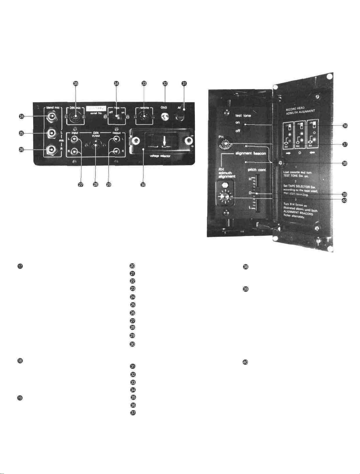
Line Input Level Controls
Mic Input Level Controls
Blend Mic Level Control
Adjustment Lid
Blend Mic Input Jack
Mic Input Jack L
Mic Input Jack R
Line Input Jacks
DIN IN/OUT Socket
Line Output Jacks
Voltage Selector Plug
You can change over either to 100, 117,
220 or 240V
AC Power Supply Cord
Ground Terminal
Remote Control Socket
19 KHz MPX Filter Switch
DIN Mic Input Socket
Test Tone Switch
Playback Head Azimuth
Alignment Screw
Alignment Beacon:
Serves to adjust the azimuth alignment of a
recording head according to each tape
Pitch Control
Standard tape speed of 1 7/8 ips is set at
click position at the center. Any speed
within
the
range
of +-6%(half
selected by turning the knob to " L"
direction for lower pitch and "H" direction
for higher pitch.
The tape speed of 1 7/8 ips. will be always
maintained in recording, regardless of the
position of the Pitch Control Knob.
tone)
can
be
Record Head Azimuth Alignment
Screw

Connections
Connecting the Line Output
Line Input and Output Connections:
1. Connect the accompanying pin plug cords
between the Line Output terminals of your
Nakamichi 700 and the Tape Monitor
terminals of your stereo amplifier.
2. Connect another pair of the pin plug
cords between the Line Input terminals of
your Nakamichi 700 and the tape
recording terminals of your stereo amplifier.
Headphone Connection:
The headphones should have an impedance
of 8 ohms.
3 If your stereo amplifier or music system
has a DIN connector socket, connect a single
DIN cable between the DIN Connector
socket on the rear panel of the Nakamichi
700 and its counter part on the
amplifier or music system.
Caution:
Do not use the LINE INPUT/OUTPUT
terminals and DIN Connector socket
simultaneously.
Connection to Digital Timer:
Set the socket of a timer to "Remote". If
you use a Remote Control, connect to the
Remote Socket of the timer.
Microphone Connection:
Microphone should be of low impedance
type of 600 ohms.
Connection for the Microphones with
DIN Connectors.
DIN Connector must be of SM type.
3
 Loading...