

NAIS TK1-1.5V, TK1-L2-H-9V, TK1-L2-H-6V, TK1-L2-H-5V, TK1-L2-H-4.5V Datasheet
...
❇
TESTING
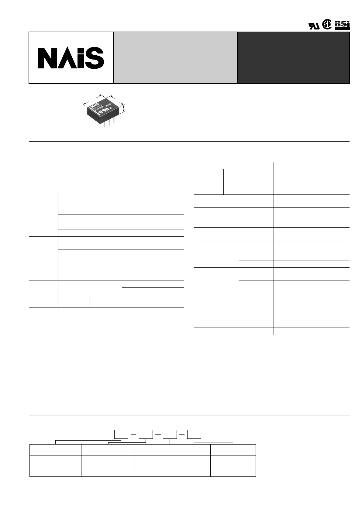
UL TRA LO W PROFILE 2 AMP .
POLARIZED RELAY
TK-RELAYS
10.6
.417
9.0
.354
4.0
.157
mm inch
SPECIFICATIONS
Contact
Arrangement 1 Form C
Initial contact resistance, max.
(By voltage drop 6 V DC 1 A)
Contact material Gold-clad silver alloy
Nominal switching capacity
(resistive load)
Max. Switching power
Rating
(resistive load)
Max. switching voltage 220 V DC
Max. switching current 2 A
Min. switching capacity ❇ 1 10 µ A 10 mV DC
140 mW (1.5 to 12 V DC)
100 mW (1.5 to 12 V DC)
200 mW (1.5 to 9 V DC)
Nominal
operating
power
Single side stable
1 coil latching
2 coil latching
Expected
life (min.
operations)
Mechanical (at 180 cpm)
Electrical
(at 20 cpm)
2 A 30 V DC
resistive
5 × 10
Note:
1This value can change due to the switching frequency, en vironmental conditions,
and desired reliability level, therefore it is recommended to chec k this with the actual load.
Remarks
* Specifications will vary with foreign standards certification ratings.
1
Measurement at same location as "Initial breakdown voltage" section.
*
2
*
By resistive method, nominal voltage applied to the coil; contact carrying current:
2 A.
3
Nominal voltage applied to the coil, excluding contact bounce time.
*
4
*
Nominal voltage applied to the coil, excluding contact bounce time without diode.
5
Half-wave pulse of sine wave: 6 ms; detection time: 10 µ s.
*
6
*
Half-wave pulse of sine wave: 6 ms.
7
Detection time: 10 µ s.
*
8
*
Refer to 4. Conditions f or operation, transport and storage mentioned in Cautions
for use (Page 178).
9
The maximum ambient temperature allows for coil temperature rise at maximum
*
allowable coil voltage.
As for the applicable range of continuous carrying current against temperature,
please refer to "Maximum value of continuous carrying current" chart. (P age 175)
50 m Ω
2 A 30 V DC
60 W
270 mW (24 V DC)
150 mW (24 V DC)
250 mW (12 V DC)
400 mW (24 V DC)
8
10
(Single side stable)
7
(1 or 2 coil latching)
5
10
FEATURES
• Low profile 4 mm .157 inch height
• High contact capacity: 2 A
• Surge withstand voltage between contact and coil: 2,500 V
(Bellcore rating)
Characteristics
Initial insulation resistance*
Initial
breakdown
voltage
Between open
contacts
Between contact and
coil
FCC surge voltage between open
contacts (10 × 160 µ s)
Surge voltage between contacts
and coil (2 × 10 µ s) [Bellcore]
Temperature rise*
2
(at 20 ° C) Max. 50 ° C
Operate time [Set time]*
Release time [Reset time]*
(at 20 ° C)
Shock resistance
Vibration
resistance
Conditions for
operation, transport and storage*
8
(Not freezing and
condensing at low
temperature)
Unit weight Approx. 1 g .035 oz.
1
Min. 1,000 M Ω (at 500 V DC)
750 Vrms for 1 min.
(Detection current: 10 mA)
1,500 Vrms for 1 min.
(Detection current: 10 mA)
1,500 V
2,500 V
3
(at 20 ° C)
4
Max. 3 ms (Approx. 1.5 ms)
[Max. 3 ms (Approx. 1 ms)]
Max. 2 ms (Approx. 1 ms)
[Max. 3 ms (Approx. 1 ms)]
Functional*
Destructive*
Functional*
Destructive
Ambient
temperature*
5
6
7
Min. 750 m/s
Min. 1,000 m/s
2
196 m/s
{20G}, 10 to 55 Hz at
double amplitude of 3.3 mm
2
294 m/s
{30G}, 10 to 55 Hz at
double amplitude of 5 mm
9
–40 ° C to +85 ° C
–40 ° F to +185 ° F
2
{75 G}
2
{100 G}
Humidity 5 to 85% R.H.
ORDERING INFORMATION
EX. TK
Contact arrangement Terminal shape
Operating function Coil voltage (DC)
1
1: 1 Form C Nil: Standard PC board terminalNil: Single side stable 1.5, 3, 4.5, 5, 6,
L2: 2 coil latching
L2 H 12V
H: Self-clinching terminal
9, 12, 24VL: 1 coil latching
173
2.54
.100
2.54
.100
2.54
.100
6-1.0 dia. holes
6-.040 dia. holes
.300
+ + +
+++
7.62
Ω ( ±
Ω ( ±
Ω ( ±
TK
TYPES AND COIL DATA (at 20 ° C 68 ° F)
1. Single side stable
Standard PC
board terminal
Part No.
Self-clinching
terminal
Nominal
voltage,
V DC
Pick-up
voltage,
V DC (max.)
Drop-out
voltage,
V DC (min.)
TK1-1.5 V TK1-H-1.5 V 1.5 1.125 0.15 93.8 16 140 2.25
TK1-3 V TK1-H-3 V 3 2.25 0.3 46.7 64.3 140 4.5
TK1-4.5 V TK1-H-4.5 V 4.5 3.38 0.45 31.1 145 140 6.7
TK1-5 V TK1-H-5 V 5 3.75 0.5 28.1 178 140 7.5
TK1-6 V TK1-H-6 V 6 4.5 0.6 23.3 257 140 9
TK1-9 V TK1-H-9 V 9 6.75 0.9 15.5 579 140 13.5
TK1-12 V TK1-H-12 V 12 9 1.2 11.7 1,028 140 18
TK1-24 V TK1-H-24 V 24 18 2.4 11.3 2,133 270 28.8
2. 1 Coil latching
Part No.
Standard PC
board terminal
Self-clinching
terminal
TK1-L-1.5 V TK1-L-H-1.5 V 1.5 1.125 1.125 66.7 22.5 100 2.25
TK1-L-3 V TK1-L-H-3 V 3 2.25 2.25 33.3 90 100 4.5
TK1-L-4.5 V TK1-L-H-4.5 V 4.5 3.38 3.38 22.2 202.5 100 6.7
TK1-L-5 V TK1-L-H-5 V 5 3.75 3.75 20 250 100 7.5
TK1-L-6 V TK1-L-H-6 V 6 4.5 4.5 16.7 360 100 9
TK1-L-9 V TK1-L-H-9 V 9 6.75 6.75 11.1 810 100 13.5
TK1-L-12 V TK1-L-H-12 V 12 9 9 8.3 1,440 100 18
TK1-L-24 V TK1-L-H-24 V 24 18 18 6.3 3,840 150 28.8
Nominal
voltage,
V DC
Set voltage,
V DC (max.)
Reset voltage,
V DC (max.)
3. 2 Coil latching
Part No.
Standard PC
board terminal
Self-clinching
terminal
TK1-L2-1.5 V TK1-L2-H-1.5 V 1.5 1.125 1.125 133.9 11.2 200 2.25
TK1-L2-3 V TK1-L2-H-3 V 3 2.25 2.25 66.7 45 200 4.5
TK1-L2-4.5 V TK1-L2-H-4.5 V 4.5 3.38 3.38 44.5 101.2 200 6.7
TK1-L2-5 V TK1-L2-H-5 V 5 3.75 3.75 40 125 200 7.5
TK1-L2-6 V TK1-L2-H-6 V 6 4.5 4.5 33.3 180 200 9
TK1-L2-9 V TK1-L2-H-9 V 9 6.75 6.75 22.2 405 200 13.5
TK1-L2-12 V TK1-L2-H-12 V 12 9 9 20.8 576 250 14.4
TK1-L2-24 V TK1-L2-H-24 V 24 18 18 16.7 1,440 400 26.4
Notes:
1. Specified value of the pick-up, drop-out, set and reset voltage is with the condition of square wave coil pulse.
2. Standard packing: Tube: 50 pcs.; Case; 1,000 pcs.
3. In case of 5 V transistor drive circuit, it is recommended to use 4.5 V type relay.
Nominal
voltage,
V DC
Set voltage,
V DC (max.)
Reset voltage,
V DC (max.)
Nominal
operating
current,
mA ( ± 10%)
Nominal
operating
current,
mA ( ± 10%)
Nominal
operating
current,
mA ( ± 10%)
Coil
resistance,
10%)
Coil
resistance,
10%)
Coil
resistance,
10%)
Nominal
operating
power,
mW
Nominal
operating
power,
mW
Nominal
operating
power,
mW
Max.
allowable
voltage,
V DC
Max.
allowable
voltage,
V DC
Max.
allowable
voltage,
V DC
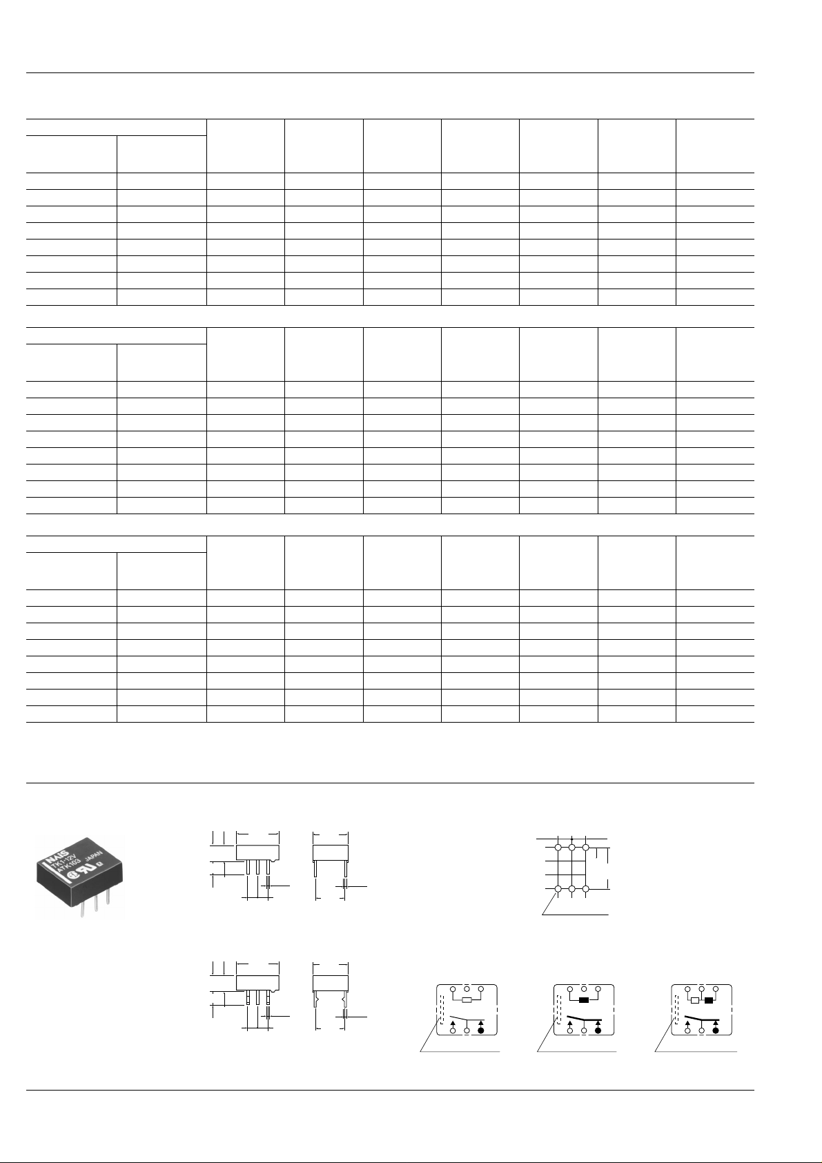
DIMENSIONS
174
Standard PC board terminal
.138
.157
3.5
10.6
4
3.75
.148
0.25
.010
2.54
.100
0.5 0.25
.020
2.54
.100
.354.417
7.62
.300
Self-clinching terminal
10.6
3.75
4
.148
.157
.138
3.5
0.25
.010
2.54
.100
0.5 0.25
.020
2.54
.100
General tolerance: ± 0.3 ± .012
.354.417
7.62
.300
mm inch
PC board pattern (Copper-side view)
9
.010
Tolerance: ± 0.1 ± .004
Schematic (Bottom view)
9
.010
• Single side stable
(Deenergized condition)
123
−+
654
Direction indication*
• 1-coil latching
(Reset condition)
123
−+
654
Direction indication*
*Orientation stripe located on top of relay.
• 2-coil latching
(Reset condition)
123
+− +
654
Direction indication*
 Loading...