

NAIS SP2-DC12V, SP2-DC24V, SP2-DC3V, SP2-DC48V, SP2-DC6V Datasheet
...
Contact arrangement Operating function Coil voltage
2: 2 Form C
4: 4 Form C
Nil: Single side stable
L2: 2 coil latching
DC 3, 5, 6, 12,
24, 48 V
2 L2 DC24VSPEx.
(Notes) 1. PC board terminal types available as option. Please consult us for details.
2. 2 Form C: Carton: 20 pcs., Case: 200 pcs.
4 Form C: Carton: 10 pcs., Case: 100 pcs.
3. UL/CSA, TÜV approved type is standard.
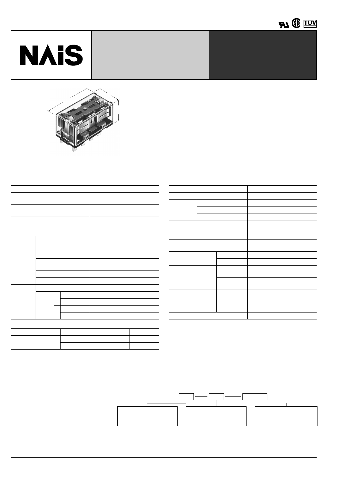
15A (2C), 10A (4C) COMPACT
POWER RELAYS WITH HIGH
SP-RELAYS
SENSITIVITY
1.969
50
a
22
.866
mm inch
a
2C 25.6 1.008
4C 36.8 1.449
SPECIFICATIONS
Contacts
Arrangement 2 Form C, 4 Form C
Initial contact resistance, max.
(By voltage drop 6 V DC 1 A)
Initial contact pressure
Contact material
2C: Approx. 0.392 N (40 g 1.41 oz )
4C: Approx. 0.196 N (20 g 0.71 oz )
Gold flashed silver alloy
Movable contact: Silver alloy
Nominal switching
capacity
Rating
(resistive
load)
Max. switching power
Max. switching voltage 2C, 4C: 250 V AC, 30 V DC
Max. switching current
2C: 15 A (AC) 10 A (DC), 4C: 10 A
Mechanical (at 180 cpm) 5 × 10
Expected
life (min.
operations)
Electrical
(at 20 cpm)
(resistive
load)
15 A 250 V AC
2C
10 A 30 V DC
10 A 250 V AC
4C
10 A 30 V DC
Coil (polarized) at 20 ° C 68 ° F
Single side stable Nominal operating power 300 mW
Latching
Minimum set and reset power 150 mW
Nominal set and reset power 300 mW
30 m Ω
Stationary contact:
2C: 15 A 250 V AC
10 A 30 V DC
4C: 10 A 250 V AC
10 A 30 V DC
2C: 3,750 VA, 300 W
4C: 2,500 VA, 300 W
7
5
10
5
10
5
10
5
10
FEATURES
• High Vibration/Shock Resistance
Vibration resistance: 18 G, amplitude 3 mm (10 to 55 Hz)
Shock resistance: 40 G (11 ms)
• Latching types available
• High Sensitivity in Small Size 150 mW pick-up, 300 mW
nominal operating power
• Wide Switching Range
From 1 mA to 15 A (2C) and 10 A (4C)
Characteristics (at 25 ° C 77 ° F 50% Relative humidity)
Max. operating speed (at rated load) 20 cpm
Initial insulation resistance*
Initial
breakdown
voltage*
Operate time*
Between open contacts
Between contact sets 3,000 Vrms
2
Between contact and coil
3
(at nominal voltage) Max. 30 ms (Approx. 25 ms)
Release time(without diode)*
(at nominal voltage)
Temperature rise
(at nominal voltage)
Shock resistance
Vibration resistance
Conditions for operation,
transport and storage*
7
(Not freezing and condensing at low temperature)
Unit weight
Remarks
* Specifications will vary with foreign standards certification ratings.
1
*
Measurement at same location as "Initial breakdown voltage" section
2
*
Detection current: 10 mA
3
Excluding contact bounce time
*
4
*
Half-wave pulse of sine wave: 11ms; detection time: 10 µ s
5
Half-wave pulse of sine wave: 6ms
*
6
*
Detection time: 10 µ s
7
Refer to 5. Conditions for operation, transport and storage mentioned in
*
AMBIENT ENVIRONMENT (Page 61).
1
1,000 M Ω at 500 V DC
1,500 Vrms
3,000 Vrms
3
Max. 20 ms (Approx. 15 ms)
Max. 40 ° C with nominal coil voltage
and at nominal switching capacity
Functional*
Destructive*
Functional*
Destructive
Ambient
temp.
4
5
6
Min. 392 m/s
Min. 980 m/s
176.4 m/s
at double amplitude of 3 mm
176.4 m/s
at double amplitude of 3 mm
–50 ° C to +60 ° C
–58 ° F to +140 ° F
2
{40 G}
2
{100 G}
2
{18 G}, 10 to 55 Hz
2
{18 G}, 10 to 55 Hz
Humidity 5 to 85% R.H.
2C: 50 g 1.76 oz ; 4C: 65 g 2.29 oz
TYPICAL APPLICATIONS
ORDERING INFORMATION
NC machines, remote control panels,
sophisticated business equipment.
252
1
28910
567
1
SET
RST
2
3
48910
567
1
28910
14 15 16
567
11 12 13
1
SET
RST
2
3
48910
14 15 16
567
11 12 13
Ω ( ±
°
TYPES AND COIL DATA (at 20 ° C 68 ° F)
Single side stable
Part No.
2 Form C 4 Form C
Nominal
voltage,
V DC
Pick-up
voltage,
V DC (max.)
Drop-out
voltage,
V DC (min.)
Nominal
operating
current, mA
Coil resis-
tance, Ω
( ± 10%) 20 ° C
Inductance,
H
(at 120 Hz)
Nominal
operating
power, mW
SP2-DC3V SP4-DC3V 3 2.1 0.3 100.0 30 Approx. 0.05 300 4.5
SP2-DC5V SP4-DC5V 5 3.5 0.5 60.2 83 0.1 300 7.5
SP2-DC6V SP4-DC6V 6 4.2 0.6 50.0 120 0.2 300 9
SP2-DC12V SP4-DC12V 12 8.4 1.2 25.0 480 0.7 300 18
SP2-DC24V SP4-DC24V 24 16.8 2.4 12.5 1,920 3.0 300 36
SP2-DC48V SP4-DC48V 48 33.6 4.8 6.2 7,700 11.2 300 72
2-coil latching
Part No. Nominal
voltage,
2 Form C 4 Form C Coil I Coil II Coil I Coil II
V DC
Set and
reset
voltage,
V DC (max.)
Nominal
operating
current,
mA
SP2-L2-DC3V SP4-L2-DC3V 3 2.1 100.0 30 30
SP2-L2-DC5V SP4-L2-DC5V 5 3.5 60.2 83 83 0.07 0.07 300 7.5
SP2-L2-DC6V SP4-L2-DC6V 6 4.2 50.0 120 120 0.1 0.1 300 9
SP2-L2-DC12V SP4-L2-DC12V
SP2-L2-DC24V SP4-L2-DC24V
SP2-L2-DC48V SP4-L2-DC48V
12 8.4 25.0 480 480 0.4 0.4 300 18
24 16.8 12.5 1,920 1,920 1.4 1.4 300 36
48 33.6 6.2 7,680 7,680 5.6 5.6 300 72
Coil resistance,
10%)
H (at 120 Hz)
Approx.
Inductance,
0.03
Approx.
Nominal
operating
power, mW
0.03 300 4.5
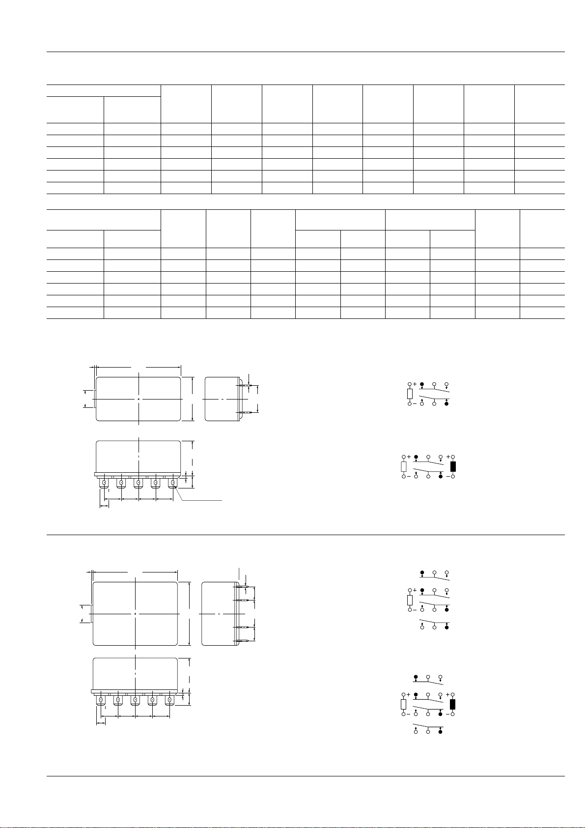
DIMENSIONS
2 Form C
Plug-in terminal
1
.039
50
1.969
0.5
.020
Schematic (Bottom view)
Single side stable
Maximum
allowable
voltage,
V DC (40 ° C)
Maximum
allowable
voltage,
V DC (40
mm inch
SP
C)
4 Form C
Plug-in terminal
10
.394
25.6
1.008
15.24
.600
(Deenergized condition)
2 coil latching
20.5
.807
1.5
.059
7.15
.281
(Reset condition)
4.75
.187
10.16
.400
10.16
.400
10.16
.400
10.16
.400
FASTON #187
Diagram shows the "reset" position when terminals 3 and 4 are
energized. Energize terminals 1 and 2 to transfer contacts.
General tolerance: ± 0.3 ± .012
Schematic (Bottom view)
Single side stable
.039
.394
1
10
50
1.969
36.8
1.449
0.5
.020
15.24
.600
7.62
.300
7.62
.300
(Deenergized condition)
2 coil latching
20.5
.807
1.5
.059
7.15
.281
10.16
10.16
10.16
.400
.400
4.75
.187
.400
10.16
.400
General tolerance: ± 0.3 ± .012
(Reset condition)
Diagram shows the "reset" position when terminals 3 and 4 are
energized. Energize terminals 1 and 2 to transfer contacts.
253
 Loading...