

(pending)
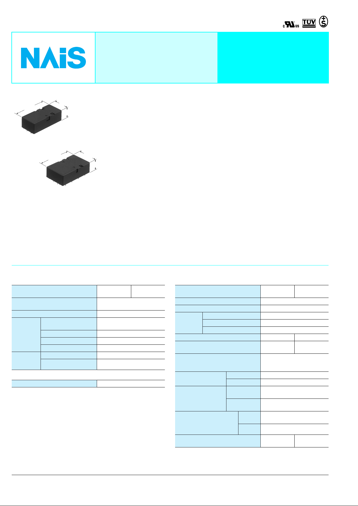
53.3±0.3
2.098±.012
2 Form A 2 Form B
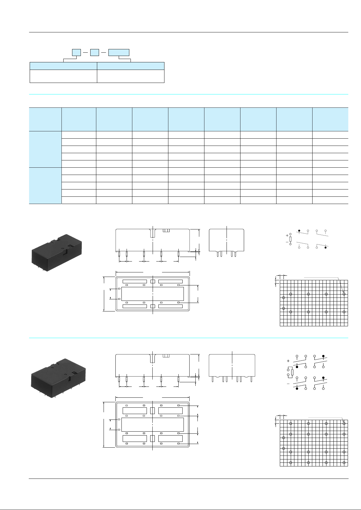
53.3±0.3
2.098±.012
4 Form A 4 Form B
25.0
.984
16.5±0.5
.650±.020
POLARISED, MONOSTABLE
SAFETY RELAY
FEATURES
• High contact reliability
High contact reliability is achieved through
the use of a double contact.
• Forced operation contacts
(2 Form A 2 Form B)
N.O. and N.C. side contacts are
connected through a card so that one
33±0.5
1.299±.020
16.5±0.5
.650±.020
mm inch
interacts with the other in movement. In
case of a contact welding, the other keeps
a min. 0.5mm .020inch contact gap.
• Independent operation contacts
(4 Form A 4 Form B)
There are 4 points of forced operation
contacts.
Each pair of contacts is free from the main
armature and is independent from each
other. So if a N.O. pair of contacts are
welded, the other 3 N.O. contacts are not
effected (operate properly) That enables
to plan a circuit to detect welding or go
back to the beginning condition.
SF-RELAYS
Double contact
• Separated chamber structure (2 Form
A 2 Form B, 4 Form A 4 Form B)
N.O. and N.C. side contacts are put in
each own space surrounded with a card
and a body-separater. That prevents short
circuit between contacts, which is caused
by their springs welding or damaged.
• High breakdown voltage 2,500 Vrms
between contacts and coil
• High sensitivity
Realizes thin shape and high sensitivity
(500 mW nominal operating power) by
utilizing high-efficiency polarized
magnetic circuit with 4-gap balanced
armature.
• Complies with safety standards
Standard products are UL, CSA, TÜV and
SEV certified. Comform to European
standards. TÜV certified (945/EL, 178/
88). Complies with SUVA European
standard.
SPECIFICATIONS
Contact
Contact arrangement
Initial contact resistance, max.
(By voltage drop 6 V DC 1 A)
Contact material Gold-flashed silver alloy
Nominal switching
Rating
(resistive)
Expected
life (min.
operations)
capacity
Max. switching power 1,500 VA, 180 W
Max. switching voltage 440 V AC, 30 V DC
Max. carrying current 6 A
Mechanical (at 180 cpm) 10
Electrical (at 20 cpm) 10
2 Form A
2 Form B
6 A 250 V AC, 6 A 30 V DC
Coil
Nominal operating power 500 mW
Remarks
* Specifications will vary with foreign standards certification ratings.
1
Measurement at same location as “Initial breakdown voltage” section
*
*2Detection current: 10mA
3
Excluding contact bounce time
*
*4Half-wave pulse of sine wave: 11ms; detection time: 10µs
*5Half-wave pulse of sine wave: 6ms
*6Detection time: 10µs
7
Refer to 6. Usage, transport and storage mentioned in NOTES
*
30 m
4 Form A
4 Form B
Ω
7
5
Characteristics
Contact arrangement
Max. operating speed 180 cpm (at nominal voltage)
Initial insulation resistance*
Initial
breakdown
voltage*
Operate time*
Release time (without diode)*
(at nominal voltage)
Temperature rise (at nominal voltage)
(at 20°C)
Shock resistance
Vibration resistance
Conditions for operation,
transport and storage*
freezing and condensing at
low temperature)
Unit weight
Between open contacts 1,300 Vrms
Between contact sets 2,500 Vrms
2
Between contact and coil 2,500 Vrms
3
(at nominal voltage) Approx. 17 ms Approx. 18 ms
1
3
Functional*
Destructive*
Functional*
Destructive
Ambient
7
(Not
temp.
Humidity 5 to 85% R.H.
2 Form A
2 Form B
Min. 1,000 MΩ at 500 V DC
Approx. 7 ms Approx. 6 ms
with nominal coil voltage and
4
5
6
38 g 1.34 oz
Max. 45°C
at 6 A carry current
Min. 294 m/s2 {30 G}
Min. 980 m/s2 {100 G}
10 to 55 Hz at double
amplitude of 2 mm
10 to 55 Hz at double
amplitude of 2 mm
–40°C to +70°C
–40°F to +158°F
Approx.
4 Form A
4 Form B
Approx.
47 g 1.66 oz
4
ORDERING INFORMATION
Ex. SF 2 D DC 5 V
Contact arrangement Coil voltage
DC 5, 12, 24, 48, 60 V2: 2 Form A 2 Form B
4: 4 Form A 4 Form B
UL/CSA, TÜV, SEV approved type is standard
TYPES AND COIL DATA (at 20°C 68°F)
Contact
arrangement
2 Form A
2 Form B
4 Form A
4 Form B
Part No.
Nominal
voltage, V DC
SF2D-DC5V 5 3.75 0.5 50 100 500 6
SF2D-DC12V 12 9 1.2 288 41.7 500 14.4
SF2D-DC24V 24 18 2.4 1.152 20.8 500 28.8
SF2D-DC48V 48 36 4.8 4.608 10.4 500 57.6
SF2D-DC60V 60 45 6.0 7.200 8.3 500 72
SF4D-DC5V 5 3.75 0.75 50 100 500 6
SF4D-DC12V 12 9 1.8 288 41.7 500 14.4
SF4D-DC24V 24 18 3.6 1.152 20.8 500 28.8
SF4D-DC48V 48 36 7.2 4.608 10.4 500 57.6
SF4D-DC60V 60 45 9.0 7.200 8.3 500 72
Pick-up
voltage, VDC
(max.)
voltage, V DC
DIMENSIONS
1. 2 Form A 2 Form B
12.7
12.7
12.7
25.0
.984
7.62
.300
5.08
.200
.500
53.3±0.3
2.098±.012
6587
1
2
109
.500
.500
TYPICAL APPLICATIONS
• Industrial equipment such as presses and machine tools
Drop-out
(min.)
.630±.020
3.0±0.5
.118±.020
1211
Coil resistance
16±0.5
0.5
.020
12.7
.500
Ω
(±10%)
Nominal
operating
current,
mA (±10%)
Nominal
operating
power, mW
Schematic (Bottom view)
5
1
2
9 101112
PC board pattern (Bottom view)
2.54
10-.055 DIA. HOLES
2.54
.100
.100
Max. allow able
voltage, V DC
mm inch
678
10-1.4 DIA. HOLES
2. 4 Form A 4 Form B
33±0.5
1.299±.020
7.62
.300
5.08
.200
General tolerance: ±0.3 ±.012
Tolerance: ±0.1 ±.004
Schematic (Bottom view)
13
14615716
16±0.5
.630±.020
0.3
.012
3.0±0.5
12.7
12.7
12.7
.500
.500
53.3±0.3
2.098±.012
1413 1615
65
1
2
109
1817 2019
.500
.118±.020
87
1211
7.62
.300
12.7
.500
7.62
.300
2.54
.100
1
5
9171018111912
2
8
20
PC board pattern (Bottom view)
2.54
.100
18-1.4 DIA. HOLES
18-.055 DIA. HOLES
General tolerance: ±0.3 ±.012
Tolerance: ±0.1 ±.004
5

REFERENCE DATA
-40 -20 0
20
40 60 80
-50
100
50
-100
Drop-out voltage
Pick-up voltage
Ambient
temperature, °C
Rate of
change, %
1. Operate/release time (without diode)
Tested sample: SF2D-DC24V
Quantity: n = 20
50
2. Temperature rise
Tested sample: SF4D-DC24V
Quantity: n = 6
Coil applied voltage: 100%V, 120%V
Contact carry current: 6A
30
3. Ambient temperature characteristics
Tested sample: SF4D-DC12V
Quantity: n = 6
40
30
20
Operate/release time, ms
10
0
Operate time
Release time
8070 10090 120 130110
Coil applied voltage, %V
Max.
x
Min.
Max.
x
Min.
25
20
15
Temperature rise, °C
10
5
0
Inside the coil
Contact
120100 110
Coil applied voltage, %V
6

THE OPERATION OF SF RELAYS (when contacts are welded)
SF relays work to maintain a normal operating state even when the contact welding occur by overloading or short-circuit
currents. It is easy to make weld detection circuits and safety circuits in the design to ensure safety even if contacts weld.
Internal Contacts Weld
If the internal contacts (No. 2, 3, 6, and 7) weld of 4a4b type, the armature becomes non-operational and the contact gaps of each of
the four form “a” contacts are maintained at greater than 0.5 mm .020 inch. Reliab le isolation is thus ensured. The 2a2b type oper ates
in the same way.
No.8
No.7
No.1
No.2
No.8
No.7
No.1
No.2
If the No. 2 contact welds.
Each of the four form “a” contacts (No. 1, 3, 5,
and 7) maintains a gap of greater than 0.5 mm
No.6
No.5
Non-energized
No.3
No.4
No.6
No.5
Energized (when no. 2 contact is welded)
No.3
No.4
.020 inch.
External Contacts Weld
If the external contacts (No. 1, 4, 5, and 8) weld of 4a4b type, gaps of greater than 0.5 mm .020 inch are maintained between adjacent
contacts and the other contacts return by an non-energized.
No.8
No.7
No.6
No.5
Energized
No.1
No.2
No.3
No.4
No.8
No.7
No.6
No.5
Non-energized (when no. 1 contact is welded)
No.1
If the No. 1 contact welds.
The adjacent No. 2 contact maintains a gap of
No.2
greater than 0.5 mm .020 inch. The other
contacts, because the coil is not energized,
return to their normal return state; each of
No.3
form “a” contacts (No. 3, 5, and 7) maintains a
contact gap of greater than 0.5 mm .020 inch;
No.4
each of the form “b” contacts (No. 4, 6, and 8)
return to a closed state.
If external connections are made in series.
Even if one of the contacts welds, the other contacts
operate independently and the contact gaps are
maintained at greater than 0.5 mm .020 inch.
Energized
Non-energized
Weld
Contact gap
min 0.5 mm .020 inch
Contact Operation Table
The table below shows the state of the other contacts. In case of form “a” contact weld the coil applied voltage is 0 V.
In case of form “b” contact weld the coil applied voltage is nominal.
No.8
No.7
No.6
No.5
Contact No. No.1 No.2 No.3 No.4
Terminal No.
20–19 12–11 8–716–15
No.1
No.2
No.3
No.4
No.5 No.6 No.7 No.8
13–14 5–69–10 17–18
Contact No.
Contact No. 1 2 3 4 5 6 7 8
1 >0.5 >0.5
2 >0.5 >0.5 >0.5 >0.5
3 >0.5 >0.5 >0.5 >0.5
Welded
contact
No.
4
≠
5 >0.5
6 >0.5 >0.5 >0.5 >0.5
7 >0.5 >0.5 >0.5 >0.5
8
≠
Note: Contact gaps are shown at the initial state.
If the contact transfer is caused by load switching, it is necessary to check the actual loading.
State of other contacts
>0.5 >0.5
≠
>0.5
>0.5
≠
≠
≠
>0.5
>0.5
≠
≠
≠
>0.5
>0.5
≠
>0.5 >0.5
>0.5 >0.5
≠
>0.5
≠
>0.5: contact gap
is kept at min. 0.5
mm .020 inch
≠
: contact closed
Empty cells: either
closed or open
7

NOTES
;;
;;
;;
;;
;;
;;
;;
;;
;;
;;
;
Tolerance range
(Avoid
condensation when
used at temperatures
higher than 0°C 32°F)
(Avoid freezing when
used at temperatures
lower than 0°C 32°F)
85
5
–40
–40
0
+32
+70
+158
Temperature, °C °F
Humidity, %R.H.
1. Coil operating power
Pure DC current should be applied to the
coil. The wav e form should be rectangular.
If it includes ripple, the ripple factor should
be less than 5%. However, check it with
the actual circuit since the characteristics
may be slightly different.
2. Coil connection
When connecting coils, refer to the wiring
diagram to prevent mis-operation or
malfunction.
3. Cleaning
For automatic cleaning, the boiling
method is recommended. A void ultrasonic
cleaning which subjects the relays to high
frequency vibrations, which may cause
the contacts to stick.
It is recommended that a fluorinated
hydrocarbon or other alcoholic solvents
be used.
4. Soldering
We recommend the following soldering
conditions
1) Automatic soldering
1) Preheating: 100°C 212°F, max. 60 s
2) Soldering: 250°C 482°F, max. 5 s
5. Others
1) If the relay has been dropped, the
appearance and characteristics should
always be checked before use.
2) The cycle lifetime is defined under the
standard test condition specified in the
JIS* C 5442-1986 standard (temperature
15 to 35°C 59 to 95°F, humidity 25 to
85%). Chec k this with the real device as it
is affected by coil driving circuit, load type,
activation frequency, activation
phase,ambient conditions and other
factors.
Also, be especially careful of loads such
as those listed below.
(1) When used for AC load-operating and
the operating phase is synchronous.
Rocking and fusing can easily occur due
to contact shifting.
(2) High-frequency load-operating
When high-frequency opening and
closing of the relay is performed with a
load that causes arcs at the contacts,
nitrogen and oxygen in the air is fused by
the arc energy and HNO
is formed. This
3
can corrode metal materials.
Three countermeasures for these are
listed here.
1. Incorporate an arc-extinguishing
circuit.
2. Lower the operating frequency
3. Lower the ambient humidity
3) For secure operations, the voltage
applied to the coil should be nominal
voltage. In addition, please note that pickup and drop-out voltage will vary
according to the ambient temperature and
operation conditions.
4) Heat, smoke, and ev en a fire may occur
if the relay is used in conditions outside of
the allowable ranges for the coil ratings,
contact ratings, operating cycle lifetime,
and other specifications. Therefore, do
not use the relay if these ratings are
exceeded. Also, make sure that the relay
is wired correctly.
5) Incorrect wiring may cause unexpected
events or the generation of heat or flames.
6) Check the ambient conditions when
storing or transporting the relays and
devices containing the relays . F reezing or
condensation may occur in the relay,
causing functional damage. Avoid
subjecting the relays to heavy loads, or
strong vibration and shocks.
6. Usage, transport and storage
conditions
1) Ambient temperature, humidity, and
atmospheric pressure during usage,
transport, and storage of the relay:
(1) T emper ature:
–40 to +70°C –40 to +158°F
(2) Humidity: 5 to 85% RH
(Avoid freezing and condensation.)
The humidity range varies with the
temperature. Use within the range
indicated in the graph below.
;
;;
;;;;
;;
;
;
;;;;;;
;;;;;
;;;;;;;
;;;;;;;
;;;;;;;;
;;;;;;;;
(3) Atmospheric pressure: 86 to 106 kPa
Temperature and humidity range for
usage, transport, and storage:
2) Condensation
Condensation forms when there is a
sudden change in temperature under high
temperature and high humidity conditions.
Condensation will cause deterioration of
the relay insulation.
3) Freezing
Condensation or other moisture may
freeze on the relay when the
temperatures is lower than 0°C 32°F. This
causes problems such as sticking of
movable parts or operational time lags.
4) Low temperature, low humidity
environments
The plastic becomes brittle if the relay is
exposed to a low temperature, low
humidity environment for long periods of
time.
2/19/2003 All Rights Reserved, © Copyright Matsushita Electric Works, Ltd.
Go To Online Catalog
 Loading...