

NAIS RG1-12V, RG1-24V, RG1-3V, RG1T-12V, RG1T-24V Datasheet
...
105
Arrangement
Contact
Coil (polarized) (at 25°C, 68°F)
1 Form C 2 Form C
Single side stable
350 mW 400 mW
1 coil latching
175 mW 200 mW
2 coil latching
350 mW 400 mW
1 Form C, 2 Form C
Contact material
Initial contact resistance, max.
(By voltage drop 6 V DC 1 A)
High frequency characteristics
(at 900 MHz)
Gold-clad silver
100 mΩ
24 W
24 V DC
1 A
1 A 24 V DC
5×10
6
10
5
Min. 65 dB Min. 65 dB
75 Ω50 Ω
Max. 1 dB Max. 1 dB
Max. 1.2
Isolation
Insertion loss
V.S.W.R. Max. 2.0
Initial insulation resistance*
1
Shock resistance
Vibration resistance
Unit weight
Ambient
temp.
Humidity 5 to 85%R.H.
Characteristics
Min. 100 MΩ at 500 V DC
Operate time*3 (at nominal voltage)
Approx. 10 ms
Release time*3 (at nominal voltage)(without diode)
Temperature rise (at 20°C)
Approx. 5 ms
Set time*
3
(at nominal voltage)
Approx. 7 ms
Reset time*
3
(at nominal voltage)
Approx. 7 ms
Max. 55°C with nominal coil voltage
across coil and at nominal switching capacity
Functional*
4
Destructive*
5
Functional*
6
1 C type
2 C type
Approx. 8 g .282 oz
Approx. 10 g .353 oz
Destructive
Min. 196 m/s
2
{20 G}
Min. 980 m/s2 {100 G}
10 to 55 Hz
at double amplitude of 2 mm
10 to 55 Hz
at double amplitude of 2 mm
–50°C to 60°C
–58°F to 140°F
Rating
(resistive)
Max. switching power
Max. switching voltage
Max. switching current
Nominal switching capacity
Initial
breakdown
voltage*
2
Between open contacts
Between contacts and coil
Between contacts and
earth terminal
1,000 Vrms
2,000 Vrms
500 Vrms
Expected life
(min. operations)
Mechanical
Electrical 1 A 24 V DC
Conditions for operation,
transport and storage
(Not freezing and condensing at low temperature)
Remarks
* Specifications will vary with foreign standards certification ratings.
*
1
Measurement at same location as “Intial breakdown voltage” section
*
2
Detection current: 10mA
*
3
Excluding contact bounce time
*
4
Half-wave pulse of sine wave: 11ms; detection time: 10µs
*
5
Half-wave pulse of sine wave: 6ms
*
6
Detection time: 10µs
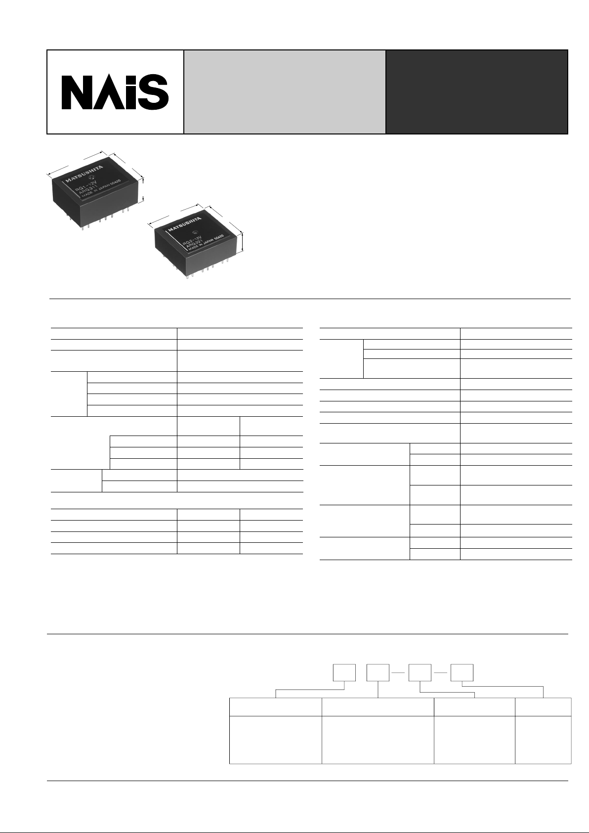
HIGH FREQUENCY
RG RELAYS WITH 1C
AND 2C CONTACTS
RG-RELA YS
19
.748
10.4
.409
25
.984
1 Form C
23
.906
9.9
.390
25
.984
2 Form C
mm inch
1T L 5VEx. RG
Contact arrangement Characteristic impedance Operating function Coil voltage
1:1 Form C
2:2 Form C
Note: Standard packing; Carton: 50 pcs. Case 500 pcs.
Nil: 75 Ω
T: 50 Ω
Nil: Single side
Nil: stable
L: 1 coil latching
L2: 2 coil latching
DC: 3, 5, 6,
9, 12, 24,
48 V
TYPICAL APPLICATIONS
• Measuring instrument
• T esting equipment
• CATV converter
• Audio visual equipment
• TV game set
ORDERING INFORMATION
• Excellent high frequency characteristics
Isolation: Min. 65dB (at 900 MHz)
Insertion loss: Max. 1.0 (at 900 MHz)
• Wide selection
Characteristic impedance: 50 Ω type and 75 Ω type
Coil: Single side stable and latching type
• 1 A 24 V DC switching capacity
• Sealed construction for automatic cleaning
• High sensitivity 350W (1 Form C) in small size
SPECIFICATIONS
106
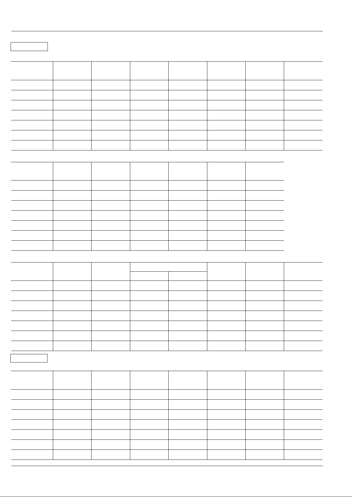
Part No.
Nominal
voltage
V DC
RG1-3V
RG1T-3V
RG1-5V
RG1T-5V
RG1-6V
RG1T-6V
RG1-9V
RG1T-9V
RG1-12V
RG1T-12V
RG1-24V
RG1T-24V
RG1-48V
RG1T-48V
Pick-up
voltage, max.
V DC
Drop-out
voltage, min.
V DC
Coil
resistance,
Ω (±10%)
Nominal
operating
current, mA
Nominal
operating
power, mW
Maximum
allowable
voltage, V DC
(40°C 104°F)
Single side stable
3
5
6
9
12
24
48
2.4
4.0
4.8
7.2
9.6
19.2
38.4
0.3
0.5
0.6
0.9
1.2
2.4
4.8
25.7
71.4
103
231
411
1,646
6,583
117.3
70.3
58.3
38.9
29.2
14.6
7.3
350
350
350
350
350
350
350
3.6
6.0
7.2
10.8
14.4
28.8
57.6
Part No.
Nominal
voltage
V DC
RG1-L-3V
RG1T-L-3V
RG1-L-5V
RG1T-L-5V
RG1-L-6V
RG1T-L-6V
RG1-L-9V
RG1T-L-9V
RG1-L-12V
RG1T-L-12V
RG1-L-24V
RG1T-L-24V
RG1-L-48V
RG1T-L-48V
Set and reset
voltage,
V DC (max.)
Coil
resistance,
Ω (±10%)
Nominal
operating
current, mA
Nominal
operating
power, mW
Maximum
allowable
voltage, V DC
(40°C 104°F)
1 coil latching
3
5
6
9
12
24
48
2.4
4.0
4.8
7.2
9.6
19.2
38.4
51.4
142.8
206.8
462.8
822.8
3,292.8
13,166.8
58.3
35.8
29.2
19.4
14.6
7.3
3.6
175
175
175
175
175
175
175
Part No.
Nominal
voltage
V DC
RG1-L2-3V
RG1T-L2-3V
RG1-L2-5V
RG1T-L2-5V
RG1-L2-6V
RG1T-L2-6V
RG1-L2-9V
RG1T-L2-9V
RG1-L2-12V
RG1T-L2-12V
RG1-L2-24V
RG1T-L2-24V
RG1-L2-48V
RG1T-L2-48V
Set and reset
voltage,
V DC (max.)
Coil 1 Coil 2
Coil resistance, Ω (±10%)
Nominal
operating
current, mA
Nominal
operating
power, mW
Maximum
allowable
voltage, V DC
(40°C 104°F)
2 coil latching
3
5
6
9
12
24
48
2.4
4.0
4.8
7.2
9.6
19.2
38.4
25.7
71.4
103
231
411
1,646
6,583
25.7
71.4
103
231
411
1,646
6,583
117.8
70.8
58.3
38.9
29.2
14.6
7.3
350
350
350
350
350
350
350
3.6
6.0
7.2
10.8
14.4
28.8
57.6
Part No.
Nominal
voltage
V DC
RG2-3V
RG2T-3V
RG2-5V
RG2T-5V
RG2-6V
RG2T-6V
RG2-9V
RG2T-9V
RG2-12V
RG2T-12V
RG2-24V
RG2T-24V
RG2-48V
RG2T-48V
Pick-up
voltage, max.
V DC
Drop-out
voltage, min.
V DC
Coil
resistance,
Ω (±10%)
Nominal
operating
current, mA
Nominal
operating
power, mW
Maximum
allowable
voltage, V DC
(40°C 104°F)
Single side stable
3
5
6
9
12
24
48
2.4
4.0
4.8
7.2
9.6
19.2
38.4
0.3
0.5
0.6
0.9
1.2
2.4
4.8
22.5
62.5
90
202.5
360
1,440
5,760
133.8
80.8
66.7
44.4
33.3
16.7
8.3
400
400
400
400
400
400
400
3.6
6.0
7.2
10.8
14.4
28.8
57.6
3.6
6.0
7.2
10.8
14.4
28.8
57.6
TYPES ANE COIL DATA (at 20°C 68°F)
RG
1 Form C
2 Form C
107
Part No.
Nominal
voltage
V DC
RG2-L-3V
RG2T-L-3V
RG2-L-5V
RG2T-L-5V
RG2-L-6V
RG2T-L-6V
RG2-L-9V
RG2T-L-9V
RG2-L-12V
RG2T-L-12V
RG2-L-24V
RG2T-L-24V
RG2-L-48V
RG2T-L-48V
Set and reset
voltage,
V DC (max.)
Coil
resistance,
Ω (±10%)
Nominal
operating
current, mA
Nominal
operating
power, mW
Maximum
allowable
voltage, V DC
(40°C 104°F)
1 coil latching
3
5
6
9
12
24
48
2.4
4.0
4.8
7.2
9.6
19.2
38.4
45
125
180
405
720
2,880
11,520
66.7
40.8
33.3
22.2
16.7
8.3
4.2
200
200
200
200
200
200
200
Part No.
Nominal
voltage
V DC
RG2-L2-3V
RG2T-L2-3V
RG2-L2-5V
RG2T-L2-5V
RG2-L2-6V
RG2T-L2-6V
RG2-L2-9V
RG2T-L2-9V
RG2-L2-12V
RG2T-L2-12V
RG2-L2-24V
RG2T-L2-24V
RG2-L2-48V
RG2T-L2-48V
Set and reset
voltage,
V DC (max.)
Coil 1 Coil 2
Coil resistance, Ω (±10%)
Nominal
operating
current, mA
Nominal
operating
power, mW
Maximum
allowable
voltage, V DC
(40°C 104°F)
2 coil latching
3
5
6
9
12
24
48
2.4
4.0
4.8
7.2
9.6
19.2
38.4
22.5
62.5
90
203
360
1,440
5,760
22.5
62.5
90
202.5
360
1,440
5,760
133.8
80.8
66.7
44.4
33.3
16.7
8.3
400
400
400
400
400
400
400
3.6
6.0
7.2
10.8
14.4
28.8
57.6
3.6
6.0
7.2
10.8
14.4
28.8
57.6
RG
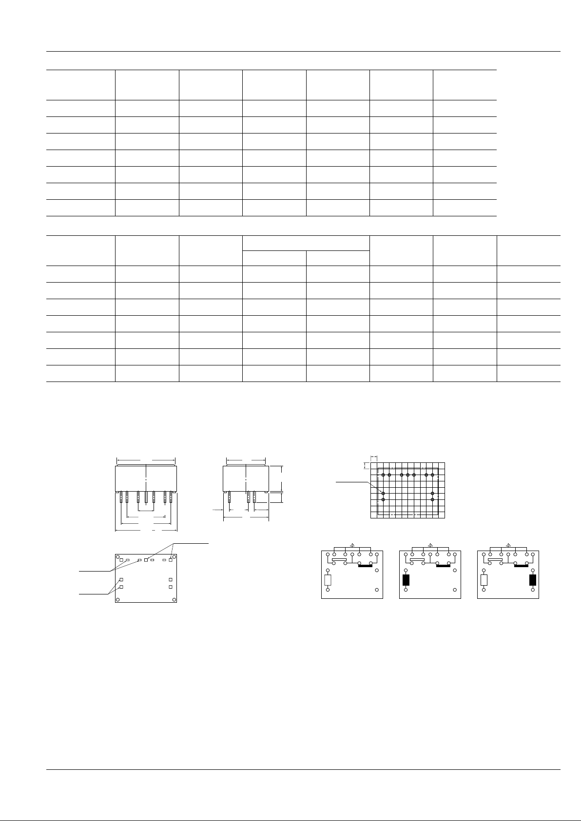
15.24
.600
5.08
.200
7.62
.300
9.9
.390
0.5
.020
3.7
.146
19
.748
2.54
.100
2.61
.103
Tolerance: ±0.3 ±.012
Tolerance: ±0.1 ±.004
Schematic (Bottom view)
Deenergized condition Reset condition Reset condition
Single side stable
PC board pattern (Copper-side view)1 Form C type
1 coil latching 2 coil latching
Set coil
Reset coil
20.32
.800
25
.984
4–0.4×0.25
.016×.010
4–0.4×0.4
.016×.016
3–0.5×0.4
.020×.016
2.54
.100
2.54
.100
11-1 DIA
11-.039 DIA.
1 2 345 6 7
15
–
16
+
–
+
–
+
+
–
17
18
1 2 345 6 7
15
16
17
18
1 2 345 6 7
15
16
17
18
21
.827
15
.591
DIMENSIONS
mm inch
 Loading...