

NAIS PQ1a-12V, PQ1a-18V, PQ1a-24V, PQ1a-3V, PQ1a-5V Datasheet
...
217
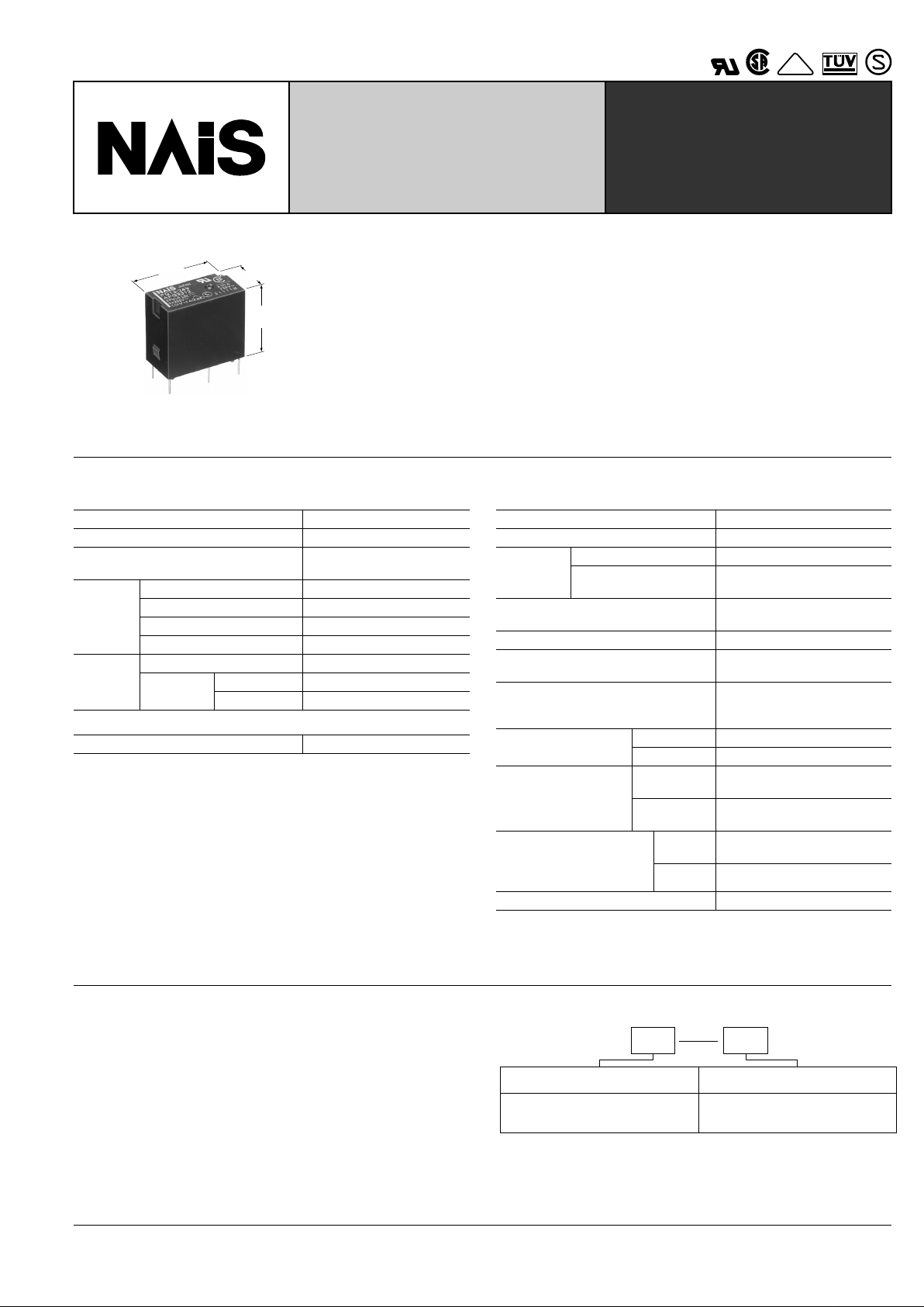
PQ-RELAYS
HIGH ELECTRICAL &
MECHANICAL NOISE
IMMUNITY RELAY
VDE
mm inch
15.6
.614
10
.394
20
.787
FEATURES
• High electrical noise immunity
• Bifurcated contact type with higher contact reliability
• High switching capacity: 5 A 250 V AC
• High sensitivity: 200 mW (Nominal)
• High surge voltage between contacts and coil: 8,000 V
• Compatible with DS-P relay terminal layout
SPECIFICATIONS
Contacts
Coil (at 20 ° C 68 ° F)
Notes:
**
1
This value can change due to the switching frequency , en vironmental conditions,
and desired reliability level, therefore it is recommended to chec k this with the actual load.
Remarks
* Specifications will vary with foreign standards certification ratings.
*
1
Measurement at same location as "Initial breakdown voltage" section
*
2
Detection current: 10mA
*
3
Wave is standard shock voltage of ± 1.2 × 50 µ s according to JEC-212-1981
*
4
Excluding contact bounce time
*
5
Half-wave pulse of sine wave: 11ms; detection time: 10 µ s
*
6
Half-wave pulse of sine wave: 6ms
*
7
Detection time: 10 µ s
*
8
Refer to 5. Conditions for operation, transport and storage mentioned in
AMBIENT ENVIRONMENT (Page 61).
Characteristics
Arrangement 1 Form A (Bifurcated)
Contact material Silver alloy
Initial contact resistance, max.
(By voltage drop 6 V DC 1 A)
50 m Ω
Rating
(resistive)
Nominal switching capacity 5 A 250 V AC, 5 A 30 V DC
Max. switching power 1,250 VA, 150 W
Max. switching voltage 250 V AC, 110 V (0.3 A)
Min. switching capacity**
1
100 µ A 100mV DC
Expected
life (min.
ope.)
Mechanical (at 180 cpm) 2 × 10
7
Electrical
(at 20 cpm)
5 A 125 V AC 2 × 10
5
5 A 250 V AC 10
5
Nominal operating power 200 mW
Max. operating speed 20 cpm at rated load
Initial insulation resistance*
1
Min. 1,000 M Ω at 500 V DC
Initial
breakdown
voltage*
2
Between open contacts 1,000 Vrms
Between contacts and
coil
4,000 Vrms
Surge voltage between contacts and
coil*
3
Min. 8,000 V
Operate time*
4
(at nominal voltage) Approx. 4 ms
Release time (without diode)*
4
(at nominal voltage)
Approx. 2 ms
Temperature rise
(Resistive at nominal voltage, contact
carrying current: 5 A, at 70 ° C)
Max. 65 ° C
Shock resistance
Functional*
5
Min. 294 m/s
2
{30 G}
Destructive*
6
Min. 980 m/s
2
{100 G}
Vibration resistance
Functional*
7
117.6 m/s
2
{12 G}, 10 to 55 Hz
at double amplitude of 2.0 mm
Destructive
205.8 m/s
2
{21 G}, 10 to 55 Hz
at double amplitude of 3.5 mm
Conditions for operation,
transport and storage*
8
(Not freezing and condensing at low temperature)
Ambient
temp.
–40 ° C to +70 ° C
–40 ° F to +158 ° F
Humidity 5 to 85%R.H.
Unit weight Approx. 7 g .25 oz
TYPICAL APPLICATIONS
• Programmable controllers
• Interface relays for Factory Automation and Communication
equipment
• Output relays for measuring equipment, timers, counters and
temperature controllers
ORDERING INFORMATION
Ex. PQ 1a 12V
Contact arrangement
1a: 1 Form A
(Bifurcated)
Coil voltage (DC)
3, 5, 6, 9, 12, 18, 24 V
Note: Standard packing: Carton: 100 pcs.; Case: 500 pcs.
UL/CSA, VDE, SEMKO approved type is standard.
PQ
218
TYPES AND COIL DATA (at 20 ° C 68 ° F)
Part No.
Nominal voltage,
V DC
Pick-up voltage,
(max.)
Drop-out
voltage,
(min.)
Nominal
operating
current, mA
Nominal
operating power ,
mW
Coil resistance,
Ω ( ±
10%)
Max. allowable
voltage, V DC
PQ1a-3V 3 2.25 0.15 66.7 200 45
180% V of
nominal voltage
(at 20 ° C 68°F)
130% V of the
nominal voltage
(at 70 ° C 158°F)
PQ1a-5V 5 3.75 0.25 40 200 125
PQ1a-6V 6 4.5 0.3 33.3 200 180
PQ1a-9V 9 6.75 0.45 22.2 200 405
PQ1a-12V 12 9 0.6 16.7 200 720
PQ1a-18V 18 13.5 0.9 11.1 200 1,620
PQ1a-24V 24 18 1.2 8.3 200 2,880
DIMENSIONS
7.62
.300
10
.394
7.62
.300
7.62
.300
10.16
.400
20
.787
15.6
.614
4.2
.165
0.4
.016
Dimension
: General tolerance
Max. 1mm .039 inch
±
0.2 ± .008
1 to 5mm .039 to .118 inch ± 0.3 ± .012
Min. 5mm .118 inch
±
0.4 ± .016
Schematic (Bottom view)
PC board pattern
(Copper-side view)
Tolerance: ± 0.1 ± .004
COM
Coil
N.O.
7.62
.300
7.62
.300
10.16
.400
4-1.3 dia.
4-.051 dia.
mm inch
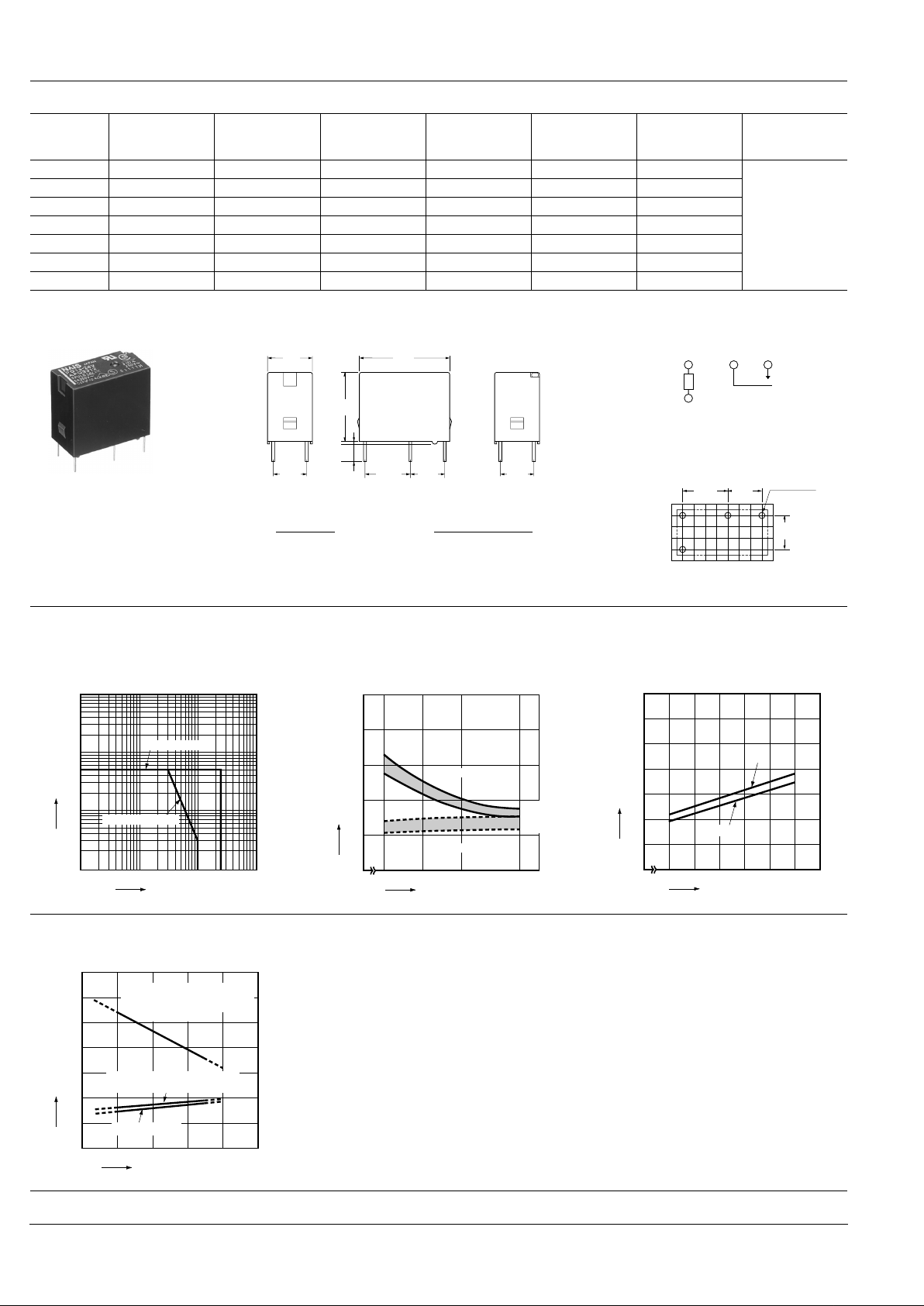
REFERENCE DATA
1. Max. switching capacity 2. Operate & release time
Tested sample: PQ1a-24V, 25 pcs.
3. Coil temperature rise
Measured portion: Inside the coil
Contact carrying current: 5 A
100
10
Contact current,A
5
1
0.3
10 30
Contact voltage, V
AC resistive load
100 250 1,000
DC resistive load
8
6
4
2
0
80 100 120 150
Coil applied voltage, %V
Operate & release time, ms
Operate time
Release time
Max.
Min.
Max.
Min.
50
70
60
40
30
20
10
0
100 110 120 130 140 150 160
50°C
Coil applied voltage,%V
Temperature rise,°C
70°C
4. Ambient temperature characteristics
Tested sample: PQ1a-24V
Contact carrying current: 5 A
300
200
100
200 40 60 80 100
Ambient temperature, °C
Coil applied voltage, %V
Allowable ambient temperature
against % coil voltage (max.
inside the coil temperature set
as 115°C 239°F)
Pick-up voltage with a hot-start
condition of 100%V on the coil
Pick-up voltage
For Cautions for Use, see Relay Technical Information (Page 48 to 76).
9/1/2000 All Rights Reserved, © Copyright Matsushita Electric Works, Ltd.
Go To Online Catalog
 Loading...