

PA
查询PA1A-12V供应商
Ω ( ±
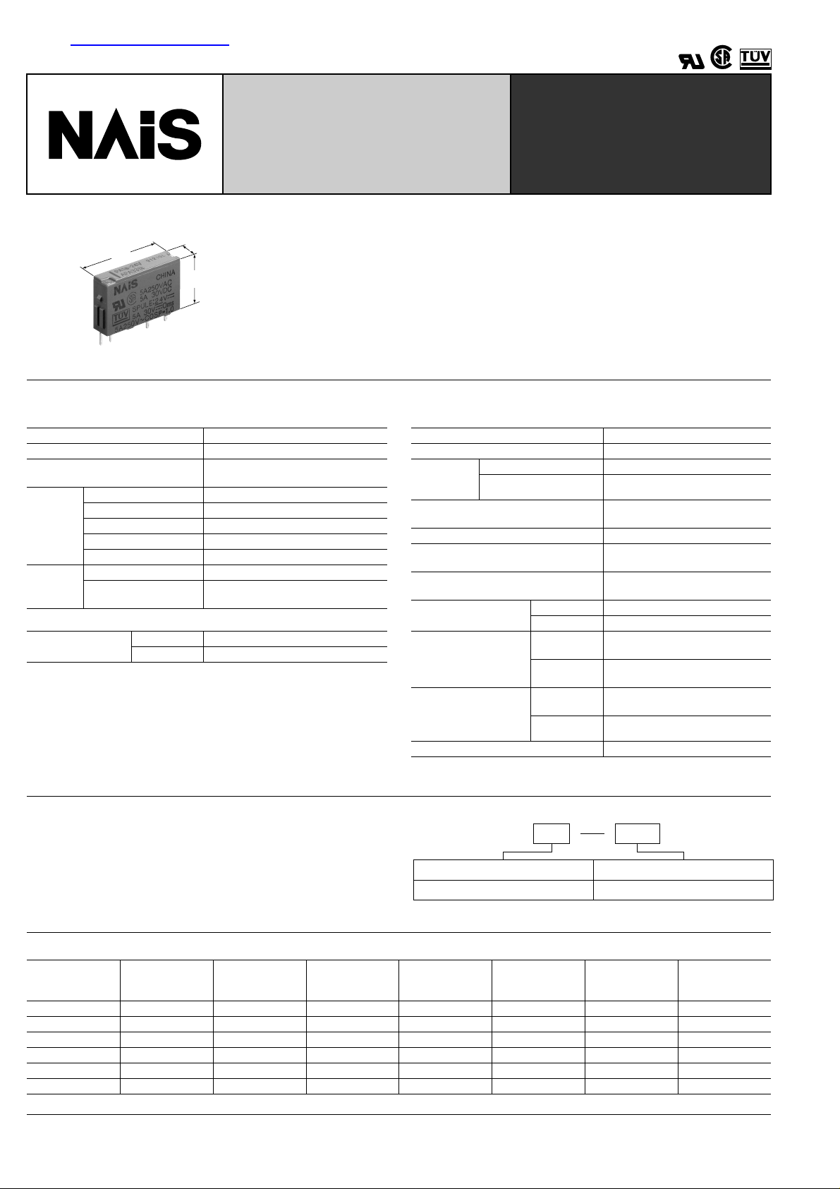
THE SLIM POWER RELAY
FEATURES
5
.787
20
.197
12.5
.492
mm inch
SPECIFICATIONS
(at 20 ° C 68 ° F)
Contacts
Arrangement 1a
Contact material Gold-clad silver alloy
Initial contact resistance, max.
(By voltage drop 6 V DC 1 A)
Rating
(resistive)
Nominal switching capacity
Maximum switching power
Maximum switching voltage
Max. switching current
5 A 250 V AC, 5 A 30 V DC
Min. switching capacity
Expected life
(min.
operations)
Mechanical 2 × 10
Electrical (at 20 cpm)
3 A 250 V AC, 3 A 30 V DC, 10
5 A 250 V AC, 5 A 30 V DC, 5 × 10
Coil (at 25 ° C 77 ° F, 50% R.H.)
Nominal operating
power
Remarks
*
Specifications will vary with foreign standards certification ratings.
1
*
Measurement at same location as "Intial breakdown voltage" section
2
Detection current: 10mA
*
3
*
Wave is standard shock voltage of ± 1.2 × 50 µ s according to JEC-212-1981
4
*
Excluding contact bounce time
5
Half-wave pulse of sine wave: 11ms; detection time: 10 µ s
*
6
*
Half-wave pulse of sine wave: 6ms
7
Detection time: 10 µ s
*
8
*
Refer to 5. Conditions for operation, transport and storage mentioned in
AMBIENT ENVIRONMENT (Page 61).
5 to 18 V DC 120 mW
24 V DC 180 mW
• Slim size (width 5 mm .197 inch, height 12.5 mm .492 inch) permits higher density
mounting
• Wide switching capacity: Control from 100 µ A 100 mV to 5 A 250 V AC, 30 V DC
• High sensitivity: 120 mW (Nominal) (5 to 18 V DC type)
• High surge voltage (4000 V) and high breakdown voltage (2000 V)
• Shock & vibration resistance (functional): Min. 147m/s
• SIL (single in line) terminal layout
• Reinforced according to IEC1131-2 (TÜV)
30 m Ω
750 VA, 90 W
250 V AC, 110 V DC
5 A
100 µ A, 100 mV DC
7
5
4
PA-RELAYS
2
{15 G}
Characteristics
Max. operating speed 20 cpm at rated load
Initial insulation resistance*
Initial break-
down
voltage*
Surge voltage between contacts and
3
coil*
Operate time*
Between open contacts 1,000 Vrms
Between contacts and coil
2
4
(at nominal voltage) Approx. 6 ms
Release time (without diode)*
(at nominal voltage)
Temperature rise
Shock resistance
Vibration resistance
Conditions for operation,
transport and storage*
8
(Not freezing and condensing at low temperature)
Unit weight Approx. 3 g .15 oz
1
Min. 1,000 M Ω at 500 V DC
2,000 Vrms
4
Approx. 3 ms
Max. 45 ° C with nominal coil voltage across
coil and at nominal switching capacity
Functional*
Destructive*
Functional*
Destructive
Ambient
temp.
5
Min. 147 m/s
6
Min. 980 m/s
Min. 147 m/s
7
at double amplitude of 2.5 mm
Min. 205.8 m/s
at double amplitude of 3.5 mm
–40 ° C to +70 ° C –40 ° F to +158 ° F
Humidity 5 to 85%R.H.
4,000 V
2
{15 G}
2
{100 G}
2
{15 G}, 10 to 55 Hz
2
{21 G}, 10 to 55 Hz
TYPICAL APPLICATIONS
• Interface relays for programmable controllers
ORDERING INFORMATION
Ex. PA
1a 12V
• Output relays for measuring equipment, timers, counters and
temperature controllers
• Industrial equipment, office equipment
TYPES AND COIL DATA
Part No.
PA1a-5VV 5 3.5 0.25 24 120 208 6
PA1a-6VV 6 4.2 0.3 20 120 300 7.2
PA1a-9VV 9 6.3 0.45 13.3 120 675 10.8
PA1a-12V 12 8.4 0.6 10 120 1,200 14.4
PA1a-18V 18 12.6 0.9 6.7 120 2,700 21.6
PA1a-24V 24 16.8 1.2 7.5 180 3,200 28.8
*1 Pulse driving
Nominal
voltage,
V DC
(at 20 ° C 68 ° F)
Pick-up
voltage,*
V DC (max.)
Drop-out
voltage,*
V DC (min.)
Nominal opera-
Contact arrangement
1a: 1 Form A
Coil voltage (DC)
5, 6, 9, 12, 18, 24V
Note: Standard packing: Tube: 25 pcs.; Case: 1,000 pcs.
UL/CSA, TÜV approved type is standard.
ting current,
mA ( ± 10%)
Nominal
operating power,
mW
Coil
resistance,
10%)
214
Max. allowable
voltage,
V DC
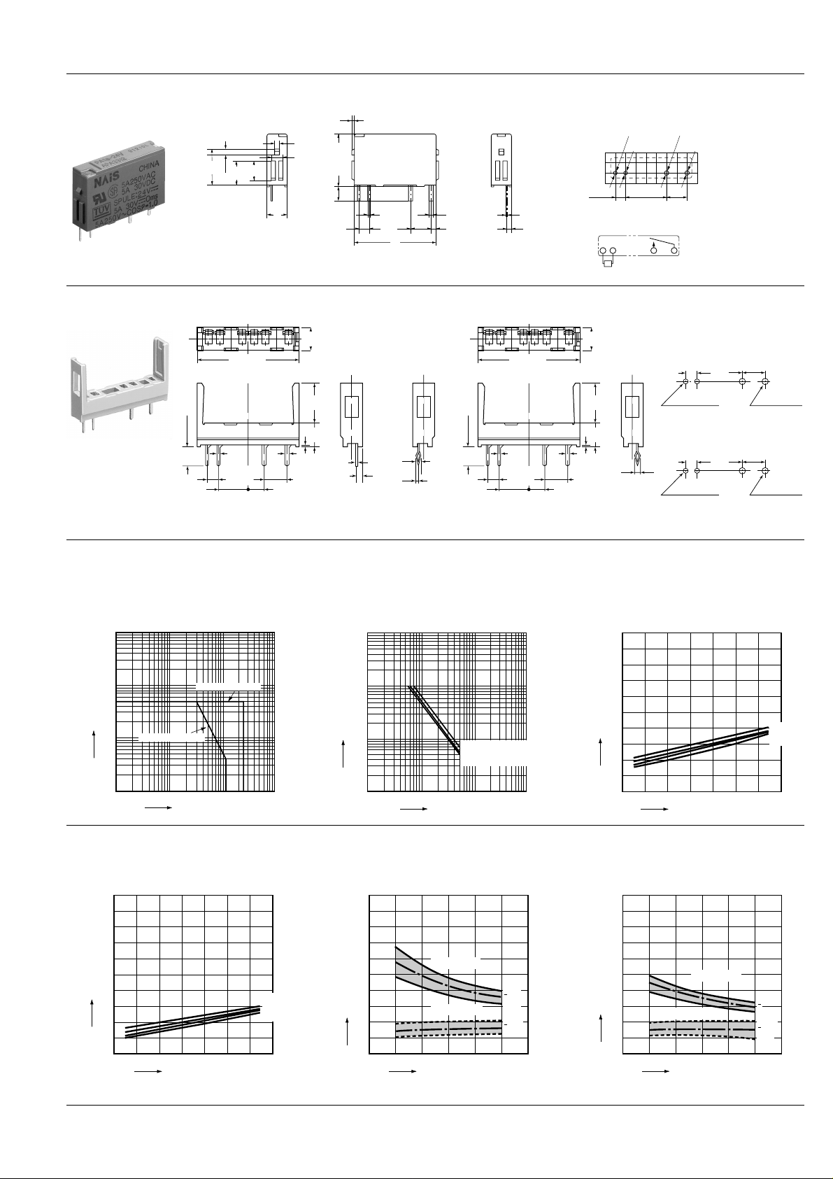
DIMENSIONS
0
1
2
3
4
5
6
7
8
9
10
80 90 100 110 120
Max.
x
x
Max.
Min.
Min.
Coil applied voltage, %V
Operate & release time, ms
Operate time
Release time
1. PA relay
8.8
.346
1.3
.051
.237
PA
mm inch
0.5
.020
1.2
.047
12.5
2.9
(12.8 max.)
.114
4.8
6
.189
.197
.492
(.504 max.)
3.5
.138
5
2.54
.100
0.5
.020
10.16
.400
.787
0.8
0.25
.031
1.11
.044
.010
1.18
.046
5.08
.200
20
General tolerance: ± 0.3 ± .012
PC board pattern (Copper-side view)
2.54
.100
1.0 dia.
.039 dia.
1.0 dia.
.039dia.
10.16
.400
1.2 dia.
.047 dia.
1.2 dia.
.047 dia.
5.08
Tolerance: ± 0.1 ± .004
.200
Schematic (Bottom view)
Coil
N.O. COM
2. Socket
PA1a-PS
Standard type
12 345 6
22.6
.890
6.35
.250
0.5
.020
2.54
.100
.157
4
PA1a-PS
Self clinching type
+0.2
5
–0.6
±.008
.197
(0.3)
(.012)
5.08
.200
±0.6
9
.354
5.3
.209
–.024
±.024
±0.6
±.024
0.25
.010
1.23
.048
.039
1.23
.048
±0.25
1
±.010
±0.6
±.024
0.8
.031
3.81
.150
12 345 6
3.9
.154
.020
6.35
.250
0.5
2.54
.100
22.6
.890
±0.6
±.024
0.8
.031
3.81
.150
(0.3)
(.012)
5.08
.200
.197
5
±0.6
9
.354
5.3
.209
+0.2
–0.6
±.008
–.024
±.024
±0.6
±.024
±0.15
1.3
±.006
.051
PA1a-PS-H
PC board pattern
(Copper-side view)
Standard type
2.54
.100
2.54
.100
10.16
.400
2-1 dia.
2-.039 dia.
Self clinching type
10.16
.400
±0.25 dia.
2-0.8
±002 dia.
2-.031
Tolerance: ± 0.1 ± .004
5.08
.200
5.08
.200
REFERENCE DATA
1. Max. switching capacity 2. Life curve 3.-(1) Coil temperature rise (120 mW)
4
100
50
30
20
No. of operations, ×10
10
0.5 1 2 3 5 10 100
AC 125 V resistive load
DC 30 V resistive load
AC 250 V resistive load
Swiching capacity, A
5
4
3
2
Contact current, A
1
DC resistive load
0.5
0.4
0.3
0.2
AC resistive load
2030 50 100
Contact voltage, V
200 300
Sample: PA1a-12V
Ambient temperature: 20 ° C 68 ° F
Measured portion: Inside the coil
100
90
80
70
60
50
40
Temperature rise, °C
30
20
10
0
100 110 120 130 140 150
Coil applied voltage, %V
2-1.2 dia.
2-.047 dia.
±0.05 dia.
2-1.2
±002 dia.
2-.047
5A
3A
2A
0A
3.-(2) Coil temperature rise (180 mW)
Sample: PA1a-24V
Ambient temperature: 20 ° C 68 ° F
Measured portion: Inside the coil
100
90
80
70
60
50
40
Temperature rise, °C
30
20
10
0
100 110 120 130 140 150
Coil applied voltage, %V
4.-(1) Operate & release time (120 mW)
Sample: PA1a-12V
No. of samples: n = 20
10
9
8
7
6
5
5A
3A
2A
0A
4
3
Operate & release time, ms
2
1
0
Operate time
Release time
80 90 100 110 120
Coil applied voltage, %V
Max.
x
Min.
Max.
x
Min.
4.-(2) Operate & release time (180 mW)
Sample: PA1a-24V
No. of samples: n = 20
215
 Loading...