

NAIS NC4D-JP-DC110V, NC2D-PL2-DC48V, NC2D-JPL2-DC48V, NC2D-JPL2-DC6V, NC2D-L2-DC24V Datasheet
...
27.8
1.094
38.1
1.500
4.1
.161
11.2
.441
°
VDE
FLA T/VERTICAL TYPE
HIGH POWER BIFURCATED
NC-RELAYS
CONTACT
38.1
1.500
25.4
1.000
10.9
.429
25.4
1.000
4C Flat type 2C Flat type
25.4
1.000
27.8
1.094
4.1
.161
4C Vertical type (PC board) 2C Vertical type (PC board)
SPECIFICATIONS
Contacts
Types Standard Amber sealed
Arrangement 2 Form C, 4 Form C
Initial contact resistance, max.
(By voltage drop 6 V DC 1 A)
Max. switching
power
2C: 1,250 VA 150 W
4C: 1,000 VA 150 W
Max. switching
Rating
(resistive
load)
voltage
Max. switching
current
Max. switching
carrying current
Min. switching
power
10
5 A 250 V AC
2C
Expected life
(minimum)
4C
5 × 10
5 A 30 V DC
10
4 A 250 V AC
5 × 10
5 A 30 V DC
Contact material Gold-clad silver nickel
Coil (Polarized) (at 25 ° C 77 ° F)
Minimum
operating power
Nominal
operating power
Minimum set and
reset power
Nominal set and
reset power
2 C single side stable Approx. 200 mW 500 mW
4 C single side stable Approx. 400 mW 500 mW
2 C single side stable Approx. 360 mW 900 mW
4 C single side stable Approx. 720 mW 900 mW
2 C 2 coil latching Approx. 450 mW
4 C 2 coil latching Approx. 900 mW
2 C 2 coil latching Approx. 800 mW
4 C 2 coil latching Approx. 1,600 mW
50 m Ω
2C: 750 VA 150 W
4C: 500 VA 150 W
250 V AC
5 A
5 A
100 µ A 1 V DC
5
at
5
at
3 A 250 V AC
5 A 30 V DC
5
at
5
at
2 A 250 V AC
5 A 30 V DC
Up to 48 V DC 110 V DC
25.4
1.000
10
5 × 10
10
5 × 10
10.9
.429
11.2
.441
mm inch
5
at
5
at
5
at
5
at
FEATURES
• Space saver — Flat series and vertical series
• High contact reliability due to bifurcated contacts
— 2C: 5 A 250 V AC, 4C: 5 A 125 V AC, 4 A 250 V AC
• Latching types available
• Low operating power
— 2C: 200 mW, 4C: 400 mW (Single side stable)
• Soldering flux inflow prevented by terminal location
• Amber sealed types available
• High breakdown voltage for transient protection
— 1,000 Vrms between open contacts, contact sets
Characteristics (at 25 ° C 77 ° F 50% Relative humidity)
Max. operating speed
Initial insulation resistance Min. 100 M Ω at 500 V DC
Initial
breakdown
voltage*
Between open contacts,
contact sets
Between contacts and
1
coil
Operate time (at nominal voltage) Approx. 6 ms
Release time (at nominal voltage) Approx. 3 ms
Operate time (latching)
(at nominal voltage)
Reset time (latching)
(at nominal voltage)
Temperature rise (at nominal voltage) Max. 65
Shock resistance
Vibration
resistance
Functional*
Destructive*
Functional*
Destructive
2
3
4
58.8 m/s
at double amplitude of 1 mm
117.6 m/s
at double amplitude of 2 mm
up to 48 V DC: –40 ° C to +70 ° C
Conditions for operation, transport and
5
storage*
(Not freezing and
condensing at low
temperature)
(Single
side
2 C
110 V DC: –40 ° C to +55 ° C
stable)
4 C –40 ° C to +55 ° C –40 ° F to +131 ° F
(2 coil latching) –40 ° C to +55 ° C –40 ° F to +131 ° F
Humidity 5 to 85% R.H.
Unit weight
Remarks
* Specifications will vary with foreign standards certification ratings.
1
Detection current: 10 mA
*
2
*
Half-wave pulse of sine wave: 11ms; detection time: 10 µ s
3
*
Half-wave pulse of sine wave: 6ms
4
Detection time: 10 µ s
*
5
*
Refer to 5. Conditions for operation, transport and storage mentioned in
AMBIENT ENVIRONMENT (Page 61).
180 cpm
1,000 Vrms
2,000 Vrms
Approx. 6 ms
Approx. 6 ms
C
Min. 98 m/s
Min. 980 m/s
2
{10 G}
2
{100 G}
2
{6 G}, 10 to 55 Hz
2
{12 G}, 10 to 55 Hz
–40 ° F to +158 ° F
–40 ° F to +131 ° F
2C/Approx. 16 g .56 oz
4C/Approx. 18 g .63 oz
223
NC
TYPICAL APPLICATIONS
Use NC Relays for power control up to 5 A or —
Tape recorders, temperature controls, video tape recorders
Telecommunications equipment, measuring controls, copiers
Date processing equipment, computer peripherals
Automatic vendors, copiers, automatic storage controls, N.C. machines
ORDERING INFORMATION
Ω ( ±
Ω ( ±
Ω ( ±
NC DEx.
2
Contact arrangement
2: 2 Form C
4: 4 Form C
(Notes) 1. Flat series are available in PC board terminal types only.
2. For VDE recognized type, add suffix VDE.
3. Standard packing Carton: 20 pcs. Case: 200 pcs.
4. UL/CSA, approved type is standard.
Type classification
Nil: Standard type
EB: Amber sealed type
EB
Housing
Nil: Vertical
series
J: Flat series
TYPE AND COIL DATA (at 20 ° C 68 ° F)
J
P L2
Mounting method
Nil: Plug-in
P: PC board
termial
(Coil data for Amber sealed types are same as those for standard types .)
DC 12V
Operating function
Nil: Single side stable
L2: 2 coil latching
Coil voltage
DC 5, 6, 12, 24, 48,
110 V
2 Form C Single side stable
Flat series Vertical series Coil voltage, V DC
PC board terminal Plug-in PC board terminal
NC2D-JP-DC5V NC2D-DC5V NC2D-P-DC5V 4.0 0.5 6.75 69.4
NC2D-JP-DC6V NC2D-DC6V NC2D-P-DC6V 4.8 0.6 8.1 100
NC2D-JP-DC12V NC2D-DC12V NC2D-P-DC12V 9.6 1.2 16.2 400
NC2D-JP-DC24V NC2D-DC24V NC2D-P-DC24V 19.2 2.4 32.4 1,600
NC2D-JP-DC48V NC2D-DC48V NC2D-P-DC48V 38.4 4.8 64.8 6,400
NC2D-JP-DC110V NC2D-DC110V NC2D-P-DC110V 88.0 11.0 121 13,500 900
Pick-up
voltage
(max.)
Drop-out
voltage
(min.)
Maximum
allowable
voltage
Coil resistance,
10%)
Nominal
operating power ,
2 Form C 2 coil latching
Flat series Vertical series Coil voltage, V DC
PC board terminal Plug-in PC board terminal
NC2D-JPL2-DC5V NC2D-L2-DC5V NC2D-PL2-DC5V 4.0 4.0 5.5 31.3
NC2D-JPL2-DC6V NC2D-L2-DC6V NC2D-PL2-DC6V 4.8 4.8 6.6 45.0
NC2D-JPL2-DC12V NC2D-L2-DC12V NC2D-PL2-DC12V 9.6 9.6 13.2 180
NC2D-JPL2-DC24V NC2D-L2-DC24V NC2D-PL2-DC24V 19.2 19.2 26.4 720
NC2D-JPL2-DC48V NC2D-L2-DC48V NC2D-PL2-DC48V 38.4 38.4 52.8 2,880
NC2D-JPL2-DC110V NC2D-L2-DC110V NC2D-PL2-DC110V 88.0 88.0 121 15,125
Pick-up
voltage
(max.)
Reset
voltage
(max.)
Maximum
allowable
voltage
Coil resistance,
10%)
Nominal
operating power ,
4 Form C Single side stable
Flat series Vertical series Coil voltage, V DC
PC board terminal Plug-in PC board terminal
NC4D-JP-DC5V NC4D-DC5V NC4D-P-DC5V 4.0 0.5 5.5 34.7
NC4D-JP-DC6V NC4D-DC6V NC4D-P-DC6V 4.8 0.6 6.6 50
NC4D-JP-DC12V NC4D-DC12V NC4D-P-DC12V 9.6 1.2 13.2 200
NC4D-JP-DC24V NC4D-DC24V NC4D-P-DC24V 19.2 2.4 26.4 800
NC4D-JP-DC48V NC4D-DC48V NC4D-P-DC48V 38.4 4.8 52.8 3,200
NC4D-JP-DC110V NC4D-DC110V NC4D-P-DC110V 88.0 11.0 121 13,500 900
Pick-up
voltage
(max.)
Drop-out
voltage
(min.)
Maximum
allowable
voltage
Coil resistance,
10%)
Nominal
operating power ,
mW
360
mW
800
mW
720
224
Ω ( ±
4 Form C 2 coil latching
Flat series Vertical series Coil voltage, V DC
Maximum
allowable
voltage
(within 2 min.)
PC board terminal Plug-in PC board terminal
Pick-up
voltage
(max.)
Reset
voltage
(max.)
NC4D-JPL2-DC5V NC4D-L2-DC5V NC4D-PL2-DC5V 4.0 4.0 5.5 15.6
NC4D-JPL2-DC6V NC4D-L2-DC6V NC4D-PL2-DC6V 4.8 4.8 6.6 22.5
NC4D-JPL2-DC12V NC4D-L2-DC12V NC4D-PL2-DC12V 9.6 9.6 13.2 90
NC4D-JPL2-DC24V NC4D-L2-DC24V NC4D-PL2-DC24V 19.2 19.2 26.4 360
NC4D-JPL2-DC48V NC4D-L2-DC48V NC4D-PL2-DC48V 38.4 38.4 52.8 1,440
NC4D-JPL2-DC110V NC4D-L2-DC110V NC4D-PL2-DC110V 88.0 88.0 121 7,560
Notes:
1.T w o coil latching rela y 4C series are f or intermittent operation only. Power should
be applied to coil continuously for no more than two minutes.
2.Coil resistance is the measured value at a coil temperature of 20 ° C. Compensate
coil resistance by plus or minus 0.4% for each degree ( ° C) of coil temperature
change.
3."Maximum allowable voltage" is that value at maximum contact rating and maximum ambient temperature. The graph shown in the data describes the inter-relationship; care should be taken to pre vent the total of ambient temperature and the
coil temperature rise from exceeding 120 ° C.
Coil resistance,
10%)
NC
Nominal
operating power ,
mW
1,600
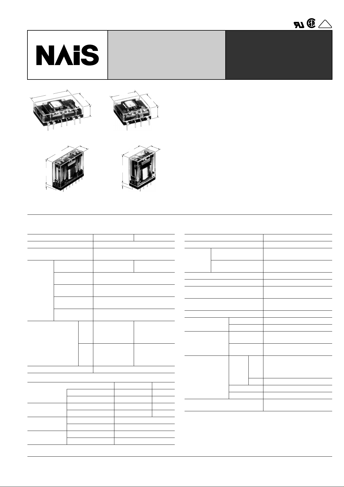
DIMENSIONS
Flat series
2C single side stable
(NC2D-JP)
(NC2ED-JP)
2C 2 coil latching
(NC2D-JPL2)
Standard type Amber sealed type
5.08
5.08
.200
7.62
.300
.200
25.4
1.000
5.08
.200
5.08
.200
7.62
.300
25.4
1.000
10.9
.429
27.94
1.100
3.5
.138
5.08
.200
7.62
.300
5.08
.200
25.4
1.000
5.08
.200
5.08
.200
7.62
.300
General tolerance: ± 0.5 ± .020
Standard type Amber sealed type
5.08
5.08
5.08
.200
5.08
.200
5.08
.200
.200
.200
5.08
.200
25.4
1.000
10.9
.429
27.94
1.100
3.5
.138
mm inch
PC board pattern (Copper-side view)
8-1.2 DIA. HOLES
8-.047 DIA. HOLES
11 12 13 14
27.94
1.100
7 5 4 2
2.54
2.54
.100
.100
Tolerance: ± 0.1 ± .004
Schematic (Top view)
14 13 12
11
4 25 7
+
–
Deenergized position
PC board pattern (Copper-side view)
10-1.2 DIA. HOLES
10-.047 DIA. HOLES
11 12 13 14
(NC2ED-JPL2)
5.08
.200
2.54
.100
25.4
1.000
5.08
.200
2.54
.100
5.08
.200
10.9
.429
27.94
1.100
3.5
.138
25.4
1.000
General tolerance: ± 0.5 ± .020
5.08
.200
2.54
.100
25.4
1.000
5.08
.200
2.54
.100
5.08
.200
25.4
1.000
10.9
.429
27.94
1.100
27.94
1.100
3.5
.138
2.54
.100
2.54
.100
7 5 4 2
0.5
.020
Tolerance: ± 0.1 ± .004
Schematic (Top view)
14 13 12
4 23 45 7
– –
Diagram shows the "reset" position
when terminals 3 and 6 are energized.
Energize terminals 4 and 5 to transfer
contacts.
11
++
225
NC
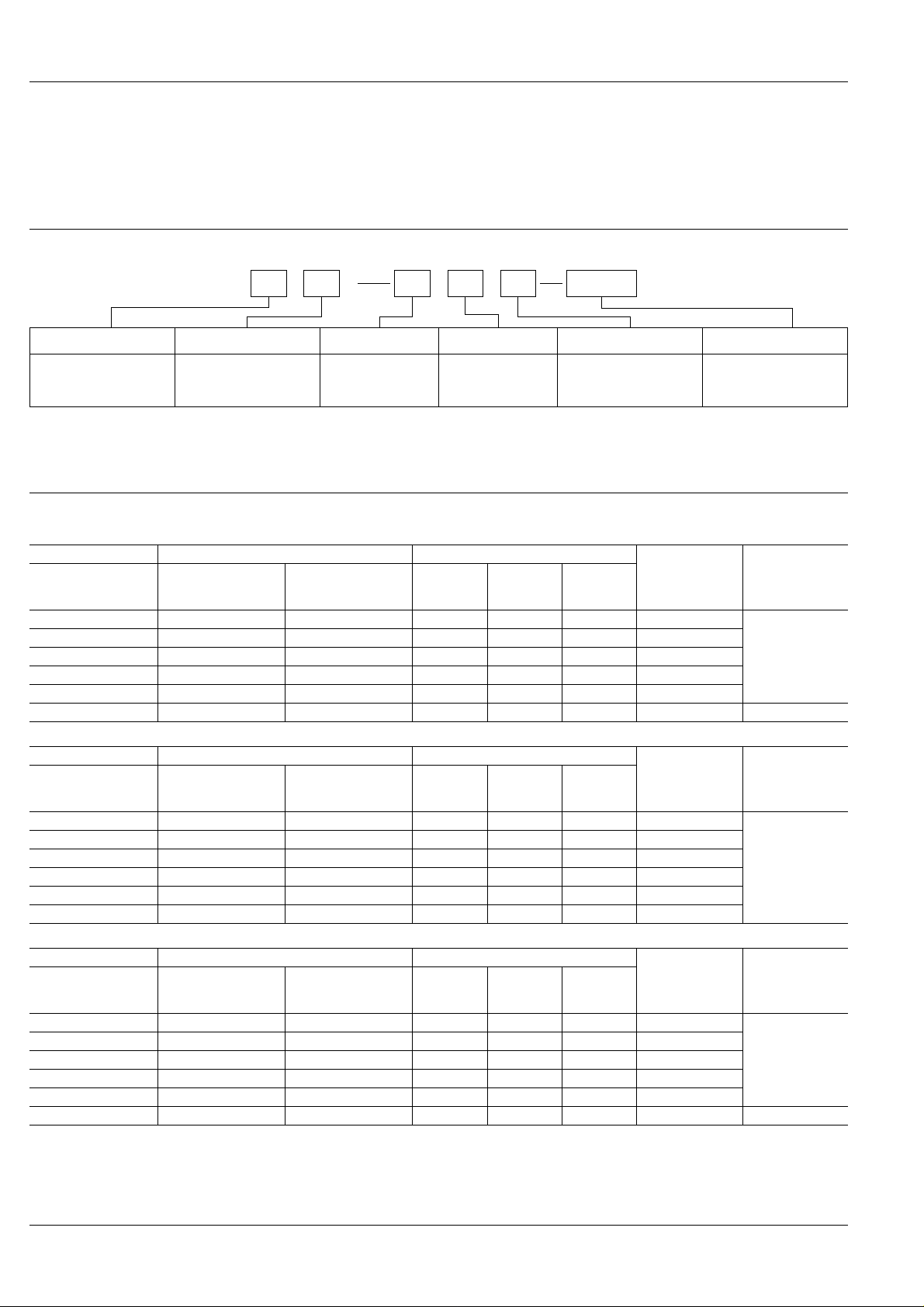
4C single side stable
(NC4D-JP)
(NC4ED-JP)
5.08
.200
5.08
.200
Standard type Amber sealed type
5.08
5.08
5.08
5.08
5.08
.200
7.62
.300
.200
.200
38.1
1.500
5.08
.200
.200
7.62
.300
.200
5.08
.200
5.08
.200
10.9
.429
27.94
1.100
3.5
.138
25.4
1.000
General tolerance: ± 0.5 ± .020
5.08
.200
5.08
.200
5.08
.200
7.62
.300
5.08
.200
5.08
.200
38.1
1.500
5.08
.200
5.08
.200
7.62
.300
5.08
.200
5.08
.200
5.08
.200
25.4
1.000
10.9
.429
PC board pattern (Copper-side view)
14-1.2 DIA. HOLES
14-.047 DIA. HOLES
10 11 12 13 14 15 16 9
27.94
1.100
27.94
1.100
3.5
.138
2.54
.100
7 5 4 2 1 8
2.54
.100
Tolerance: ± 0.1 ± .004
Schematic (Top view)
16 15 14 13 12 11 10 9
4 12 75 8
+
–
Deenergized position
mm inch
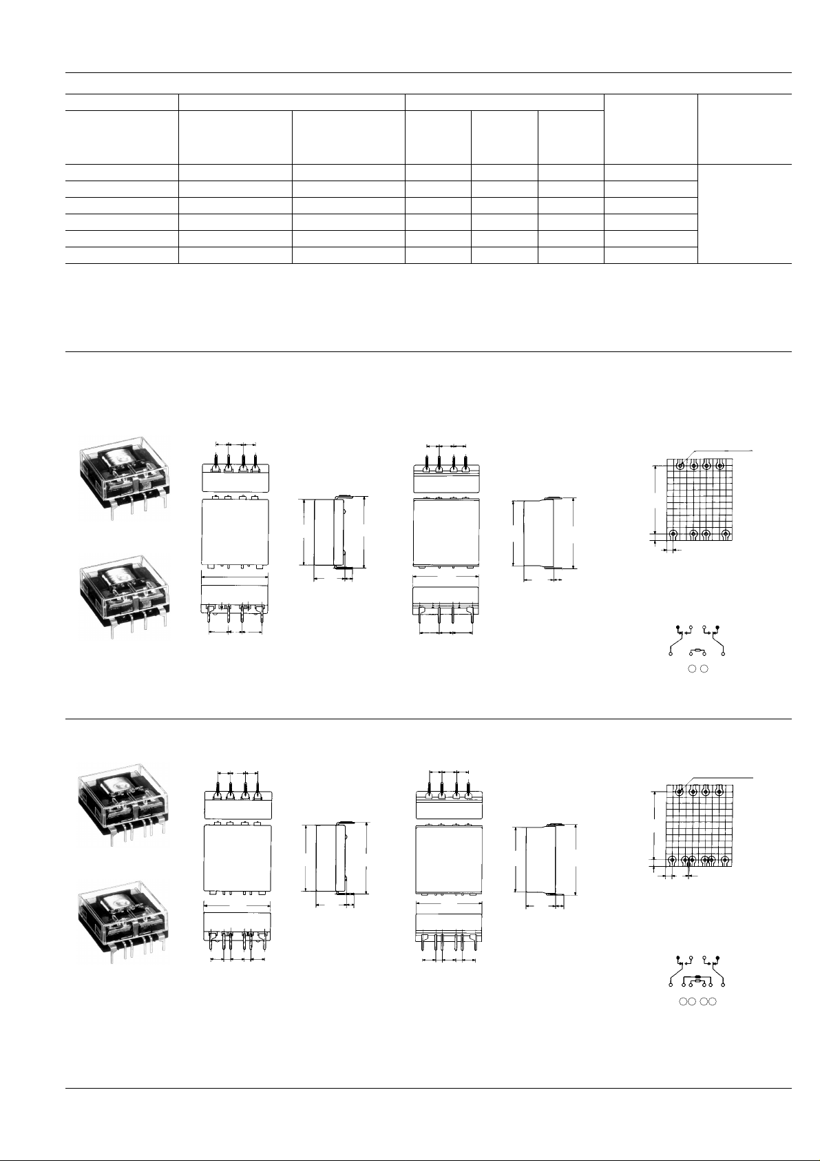
4C 2 coil latching
(NC4D-JPL2)
(NC4ED-JPL2)
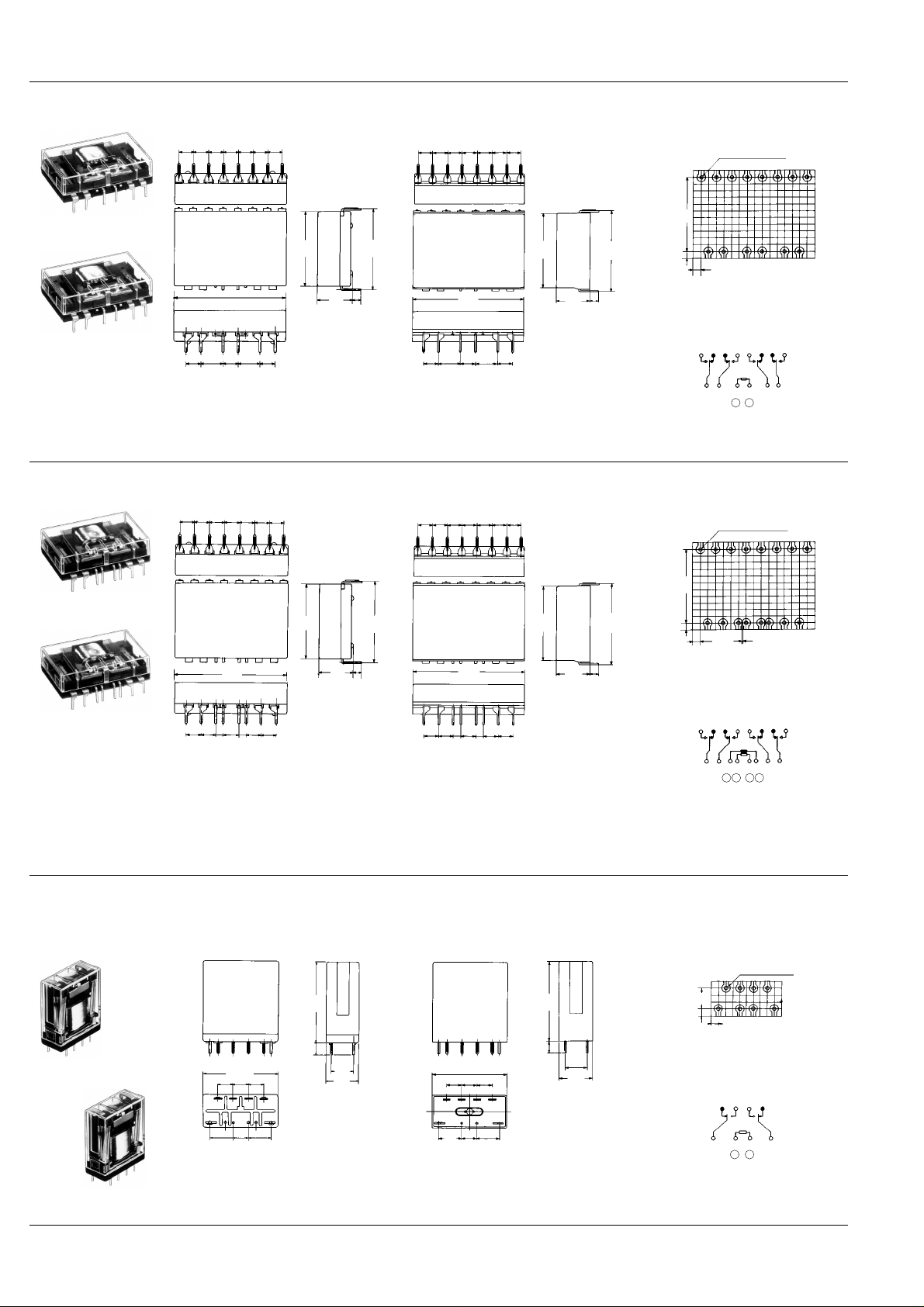
Slim series
PC board series
2C single side stable
(NC2D-P)
(NC2ED-PL2)
5.08
.200
5.08
.200
Standard type Amber sealed type
5.08
5.08
5.08
5.08
5.08
.200
5.08
.200
.200
2.54
.100
.200
38.1
1.500
5.08
.200
2.54
.100
.200
5.08
.200
.200
5.08
.200
5.08
.200
25.4
1.000
10.9
.429
27.94
1.100
3.5
.138
5.08
.200
5.08
.200
5.08
.200
5.08
.200
5.08
.200
2.54
.100
5.08
.200
38.1
1.500
5.08
.200
2.54
.100
5.08
.200
General tolerance: ± 0.5 ± .020
Standard type Amber sealed type
27.8
1.094
4.1
7.62
.300
.161
7.62
.300
11.2
.441
235467
25.4 1.000
5.08
5.08
.200
.200
5.08
7.62
.200
.300
5.08
.200
7.62
.300
General tolerance: ± 0.5 ±.020
25.4
1.000
5.08
5.08
5.08
.200
.200
.200
11 12 13 14
5.08
7.62
.200
.300
5.08
.200
5.08
.200
5.08
.200
5.08
.200
25.4
1.000
1.094
4.1
.161
27.8
10.9
.429
7.62 .300
11.2
.441
PC board pattern (Copper-side view)
16-1.2 DIA. HOLES
16-.047 DIA. HOLES
10 12 11 13 15 14 16 9
27.94
1.100
27.94
1.100
3.5
.138
2.54
.100
7 5 6 3 4 2 1 8
2.54
0.5
.100
.020
Tolerance: ± 0.1 ± .004
Schematic (Top view)
16 15 14 13 12 11 10 9
4 3 12 75 6 8
++
– –
Diagram shows the "reset" position
when terminals 3 and 6 are energized.
Energize terminals 4 and 5 to transfer
contacts.
PC board pattern (Copper-side view)
8-1.2 DIA. HOLES
8-.047 DIA. HOLES
12 11 13 14
7.62
.300
7 5 4 2
2.54
2.54
.100
.100
Tolerance: ±0.1 ±.004
Schematic (Bottom view)
11 12 13 14
5 274
+
–
Deenergized position
226
 Loading...