

NAIS HC4HTM-DC6V, HC4HTM-DC48V, HC4HTM-DC24V, HC4HTM-DC12V, HC4HTM-DC110V Datasheet
...
395
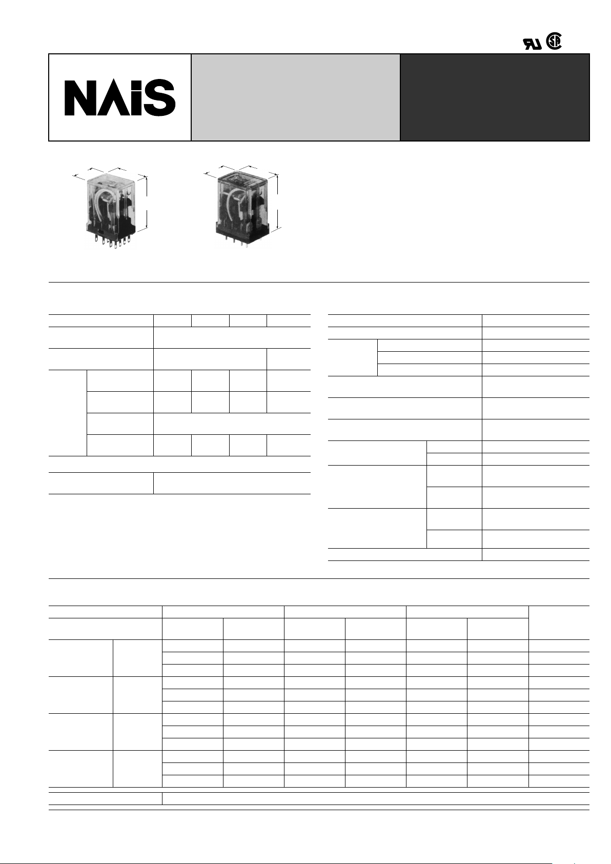
HC-RELAYS
MINIATURE RELAY
FOR WIDER APPLICA TIONS
VDE
1c, 2c, 4c
HCE Amber Relays
mm inch
27.2
1.071
35.2
1.386
20.8
.819
27.2
1.071
35.2
1.386
20.8
.819
FEATURES
• Extra long life — Min. 10
8
mechanical operations (DC type)
• 4 contact arrangements
4 Form C (for 5 A 250 V AC),
3 Form C (for 7 A 250 V AC),
2 Form C (for 7 A 250 V AC),
1 Form C (for 10 A 250 V AC)
• Applicable to low to high level loads (100 µ A to 10A)
• Amber sealed types available
• Bifurcated contact types available as HC4D
SPECIFICATIONS
Contacts
Coil
Remarks
* Specifications will vary with foreign standards certification ratings.
*
1
Detection current: 10 mA
*
2
Excluding contact bounce time
*
3
Half-wave pulse of sine wave: 11ms; detection time: 10 µ s
*
4
Half-wave pulse of sine wave: 6ms
*
5
Detection time: 10 µ s
*
6
Refer to 5. Conditions for operation, transport and storage mentioned in
AMBIENT ENVIRONMENT (Page 61).
Characteristics
Arrangement 1 Form C 2 Form C 3 Form C 4 Form C
Initial current resistance, max.
(By voltage drop 6 V DC 1 A)
30 m
Ω
Contact material Gold-flashed silver alloy
Gold-clad
silver nickel
Rating
(resistive)
Nominal
switching capacity
10 A
250 V AC
7 A
250 V AC
7 A
250 V AC
5 A
250 V AC
Max. switching
power
2,500 VA 1,750 VA 1,750 VA 1,250 VA
Max. switching
voltage
250 V AC
Max. switching
current
10 A 7 A 7 A 5 A
Nominal operating power
AC (50Hz): 1.3VA, AC (60Hz): 1.2 VA
DC:0.9 to 1.1W
Max. operating speed 20 cpm (at max. rating)
Initial insulation resistance Min. 1,000 MW at 500 V DC
Initial
breakdown
voltage*
1
Between open contacts 700 Vrms for 1 min.
Between contact sets 700 Vrms for 1 min.
Between contact and coil 2,000 Vrms for 1 min.
Operate time*
2
(at nominal voltage)
(at 20°C)
Approx. 10 ms
(DC, AC type)
Release time (without diode)*
2
(at nominal voltage) (at 20°C)
Approx. 5 ms (DC type)
Approx. 10 ms (AC type)
Temperature rise, max. (at 70 ° C)
(at nominal voltage)
80 ° C
Shock resistance
Functional*
3
Min. 196 m/s
2
{20 G}
Destructive*
4
Min. 980 m/s
2
{100 G}
Vibration resistance
Functional*
5
10 to 55 Hz at double
amplitude of 1 mm
Destructive
10 to 55 Hz at double
amplitude of 2 mm
Conditions for operation,
transport and storage*
6
(Not freezing and condensing at low temperature)
Ambient
temp.
–50 ° C to +70 ° C
–58 ° F to +158 ° F
Humidity 5 to 85% R.H.
Unit weight Approx. 30g 1.06 oz
Expected life (min. operations)
Electrical (at 20 cpm)
Voltage 125 V AC 250 V AC 30 V DC
Expected life
Load
Resistive
(cos ϕ = 1)
Inductive
(cos ϕ
]
0.4)
Resistive
(cos ϕ = 1)
Inductive
(cos ϕ
]
0.4)
Resistive Inductive
HC1
(1 Form C)
Current
10A 5A 10A 3A — — 2 × 10
5
7A 3A 7A 2.5A 3A 1A 5 × 10
5
5A 2A 5A 1.5A — — 1 × 10
6
HC2
(2 Form C)
Current
7A 3.5A 7A 2A — — 2 × 10
5
5A 2.5A 5A 1.5A 3A 0.6A 5 × 10
5
3A 1.5A 3A 1A — — 1 × 10
6
HC3
(3 Form C)
Current
7A—7A———1
×
10
5
— 3.5A — 2A — — 2 × 10
5
5A — 5A — 3A 0.4A 5 × 10
5
HC4
(4 Form C)
Current
5A 2A 5A 1A — — 2 × 10
5
3A 1A 3A 0.8A 3A 0.4A 5 × 10
5
2A 0.5A 2A 0.4A — — 1 × 10
6
Mechanical life (at 180 cpm) DC type: 10
8
, AC type: 5 × 10
7
HC
396
TYPICAL APPLICATIONS
Transportation, power station control
equipment, refrigerators, building control
equipment, office machines, coin operat-
ed machines, amusement devices, medical equipment, etc.
ORDERING INFORMATION
EX. HC 4 D H AC 240V
Contact arrangement
1: 1 Form C
2: 2 Form C
3: 3 Form C
4: 4 Form C
Nil: Standard type
D: Bifurcated contact type
(HC4D only. See Page 400.)
K: Latching relay type
(HC2K only. See Page 401.)
H: Plug-in
HP: PC board terminal
HTM: Top mounting
HL: Light emitting diode
wired, plug-in
HPL: Light emitting
diode wired, PC
board
AC 6, 12, 24, 48, 120/240 V
DC 6, 12, 24, 48, 110 V
Type classifications Terminal arrangement Coil voltage
Notes:
1. When ordering VDE recognized types, add suffix VDE.
2. HC3 (3 Form C) series are not approved by VDE.
3. AC 48 V type is not available for LED wiring.
4. Standard packing Carton: 20 pcs.; Case: 200 pcs.
5. UL/CSA approved type is standard.
COIL DATA
(Common for Standard, Amber sealed and Bifurcated contact types)
DC Type at 20 ° C 68 ° F
AC Types (50/60 Hz) at 60 Hz, 20 ° C 68 ° F
Coil voltage,
V DC
Pick-up voltage,
V DC (max.)
Drop-out voltage,
V DC (min.)
Max. allowable
voltage,
V DC
Coil resistance,
Ω ( ±
10%)
Nominal coil
current,
mA ( ± 10%)
Operating power, W
Nominal Minimum
6 4.8 0.6 6.6 40 150 0.9 0.58
12 9.6 1.2 13.2 160 75 0.9 0.58
24 19.2 2.4 26.4 650 37 0.9 0.58
48 38.4 4.8 52.8 2,600 18.5 0.9 0.58
110 88.0 11.0 121.0 10,000 10 1.0 0.64
Coil voltage,
V AC
Pick-up voltage,
V AC (max.)
Drop-out voltage,
V AC (min.)
Max. allowable
voltage,
V AC
Nominal coil
current,
mA ( ± 20%)
Operating power, VA
Nominal Minimum
6 4.8 1.8 6.6 200
1.20 0.77
12 9.6 3.6 13.2 100
24 19.2 7.2 26.4 50
48 38.4 14.4 52.8 25
110/120 96 36 132 10.9/11.9
220/240 176.0 66.0 264.0 6.0/6.5
NOTES:
1. The range of coil current is ± 15% for AC
(60 Hz), and ± 10% for DC, at 20 ° C.
2. The relay is applicable to the range of
80 % to 110% of the nominal coil voltage.
Howev er, it is recommended that the rela y
be used in the range of 85% to 110% to
take temporary voltage variations into
consideration.
3. The coil resistance of DC types is the
measured value at a coil temperature of
20 ° C. Please compensate coil resistance
by ± 0.4% for each degree centigrade coil
temperature change.
4. All AC 240 V types are rated for double
coil voltages, both AC 220 V and A C 240 V.
5. For use with 220 V or 240 V DC, connect a resistor as suggested in the chart
below, in series with the 110 V DC relay.
Voltage
1 Form C, 2 Form C,
3 Form C, 4 Form C
220 V DC 11 k Ω (5 W)
240 V DC 13 k Ω (5 W)
HC
397
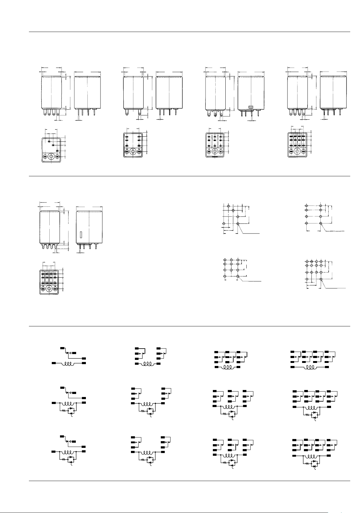
DIMENSIONS
(Common for standard, Amber sealed and Bifurcated contact (4C only) types)
Plug-in type
HC1-H (1 Form C) HC2-H (2 Form C) HC3-H (3 Form C) HC4-H (4 Form C)
General tolerance: ± 0.2 ± .008
20.8
.819
0.6
.024
6.4
.252
0.5
.020
4.41
.174
4.06
.160
6.35
.250
6.35
.250
4.45
.175
13.35
.526
2.54
.100
1
.039
27.2
1.071
35.2
1.386
1.7
.067
1.7
.067
20.8
.819
0.6
.024
6.4
.252
0.5
.020
4.41
.174
4.06
.160
6.35
.250
6.35
.250
13.35
.526
2.54
.100
1
.039
27.2
1.071
35.2
1.386
1.7
.067
1.7
.067
20.8
.819
0.6
.024
6.4
.252
0.5
.020
4.41
.174
4.06
.160
6.35
.250
6.35
.250
13.35
.526
2.54
.100
1
.039
27.2
1.071
35.2
1.386
1.7
.067
1.7
.067
20.8
.819
0.6
.024
6.4
.252
0.5
.020
4.41
.174
4.06
.160
6.35
.250
6.35
.250
4.45
.175
13.35
.526
2.54
.100
1
.039
27.2
1.071
35.2
1.386
1.7
.067
1.7
.067
mm inch
PC board type
HC4-H (4 Form C)
General tolerance: ± 0.2 ± .008
20.8
.819
0.6
.024
3.5
.138
0.5
.020
4.41
.174
4.06
.160
6.35
.250
6.35
.250
4.45
.175
13.35
.526
1.5
.059
1.5
.059
1
.039
27.2
1.071
35.2
1.386
1.7
.067
1.7
.067
Dimensions of HC1-HP,
HC2-HP, HC3-HP are the
same as those of plug-in type
except shapes of terminals.
PC board pattern (Copper-side view)
1c 2c
4.1
.161
16.8
.661
10.4
.409
8.9
.350
4.45
.175
13.35
.526
5-2 dia.
5-.079 dia.
4.1
.161
16.8
.661
10.4
.409
13.35
.526
8-2 dia.
8-.079 dia.
3c 4c
Tolerance: ± 0.1 ± .004
4.1
.161
16.8
.661
10.4
.409
13.35
.526
11-2 dia.
11-.079 dia.
4.1
.161
16.8
.661
10.4
.409
8.9
.350
4.45
.175
13.35
.526
14-2 dia.
14-.079 dia.
Note: Special PC terminal with 0.9 mm (.035 inch) width available with
suffix "-31".
Schematic (bottom view)
HC1-H, HC1-HP (1 Form C)
LED AC type
LED DC type
HC2-H, HC2-HP (2 Form C)
LED AC type
LED DC type
HC3-H, HC3-HP (3 Form C)
LED AC type
LED DC type
HC4-H, HC4-HP (4 Form C)
LED AC type
LED DC type
2
7
12
14
13
7
12
14
2
13
(∼)
(∼)
2
7
12
14
13
(−)
(+)
14
8
12
14
5
9
13
14
13
(∼)
(∼)
14
8
12
5
9
14
13
(−)
(+)
14
8
12
5
9
1
14
4
7
2
5
8
3
6
9
13
14
13
(∼)
(∼)
1
4
7
2
5
8
3
6
9
14
13
(−)
(+)
1
4
7
2
5
8
3
6
9
1
14
5
9
2
6
10
3
7
11
4
8
12
13
14
13
(∼)
(∼)
1
5
9
2
6
10
3
7
11
4
8
12
14
13
(−)
(+)
1
5
9
2
6
10
3
7
11
4
8
12
HC
398
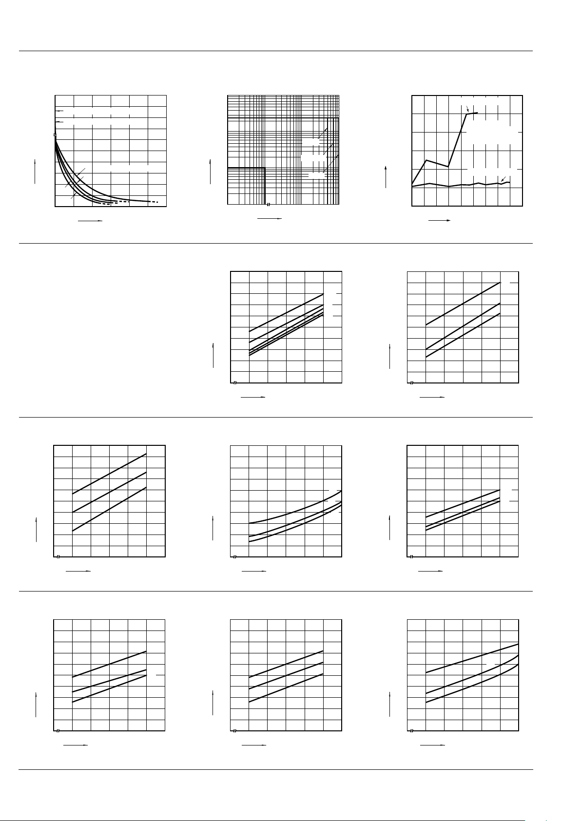
REFERENCE DATA
1. Life curve
Load: 250 V AC resistive load
2. Switching capacity range 3. H2S gas test
246810
100
200
300
400
500
5,000
10,000
1c
2c
3c
4c
Load current, A
Life, ×10
4
times
Mechanical life (DC type)
Mechanical life (AC type)
(250 V AC cosϕ = 1)
10mA
100
10
250
1A1mA
7A
5A 10A
HC1c
HC4c
HC2c, 3c
AC current
AC voltage, V
10
1
10mΩ
100mΩ
1Ω
10Ω
100Ω
20 50 100
Exposure time, Hrs.
200 500
1000 2000 5000
Standard HC relay
HCE Amber relay
Gas density:
2 to 5 ppm
Temperature: 40°C
Humidity: 90% RH
Contact resistance
4. Coil temperature rise
Measured portion: Inside the coil Note: When
the nominal voltage is applied to AC 120 or 240
V coil types respectively , the figures of coil temperature rise increase by approx. 10 degrees to
the ones shown on each graph.
HC1 AC coil
Ambient temperature: 25°C 77°F
HC2 AC coil
Ambient temperature: 30°C 86°F
80 90 100 110 120
0
10
20
30
40
50
60
70
80
90
100
10A
7A
0A
2A
5A
Coil applied voltage, %V
Temperature rise, °C
80 90 100 110 120
0
10
20
30
40
50
60
70
80
90
100
7A
5A
0A
Coil applied voltage, %V
Temperature rise, °C
HC3 AC coil
Ambient temperature: 18°C 64°F
HC4 AC coil
Ambient temperature: 15 to 21°C 59 to 70°F
HC1 DC coil
Ambient temperature: 29°C 84°F
80 90 100 110 120
0
10
20
30
40
50
60
70
80
90
100
5A
7A
0A
Coil applied voltage, %V
Temperature rise, °C
80 90 100 110 120
0
20
40
60
80
100
120
140
160
180
5A
3A
1A
Coil applied voltage, %V
Temperature rise, °C
80 90 100 110 120
0
10
20
30
40
50
60
70
80
90
100
10A
5A
0A
Coil applied voltage, %V
Temperature rise, °C
HC2 DC coil
Ambient temperature: 29°C 84°F
HC3 DC coil
Ambient temperature: 29°C 84°F
HC4 DC coil
Ambient temperature: 17 to 18°C 62 to 64°F
80 90 100 110 120
0
10
20
30
40
50
60
70
80
90
100
7A
5A
0A
Coil applied voltage, %V
Temperature rise, °C
80 90 100 110 120
0
10
20
30
40
50
60
70
80
90
100
7A
5A
0A
Coil applied voltage, %V
Temperature rise, °C
80 90 100 110 120
0
10
20
30
40
50
60
70
80
90
100
5A
3A
1A
Coil applied voltage, %V
Temperature rise, °C
 Loading...