

NAiS GT10 Technical Manual

PROGRAMMABLE DISPLAY
GT10
Technical Manual
Includes installation guide for GTWIN screen
creation software.
is a global brand name of Matsushita Electric Works.

SAFETY PRECAUTIONS
[ALWAYS OBSERVE THESE PRECAUTIONS]
Before installing, operating, servicing or inspecting this product, please make sure
you have read this manual and the explanations of how procedures are carried out,
and make sure the product is used correctly.
This manual uses two safety standard levels: ”WARNING” and ”CAUTION”.
WARNING
Erroneous handling of an item marked with this label can cause fatal or critical
injury to the user.
D If this product is used in applications where accidents involving bodily
injury and/or significant damage may be conceivable, measures should
be taken to ensure adequate safety, such as the use of duplicate safety
mechanisms.
D The functions of the GT10 should not be used to design systems which
may pose a threat to human life or which may cause severe injury or
damage. Designs should include safety mechanisms for use in the
event that switch functions do not function correctly.
D Do not use this product in an environment where combustible gases are
present. This can cause explosion.
D This product contains a secondary battery (lithium and vanadium). Do
not dispose of it by incineration. This can cause it to explode.
CAUTION
Erroneous handling of an item marked with this label can cause injury to the
user, or physical damage to property.
D This product should not be used outside of the stated specifications
ranges for ratings, service life, configuration factors and other
elements. This can cause abnormal generation of heat and smoke.
D The operational force of the touch panel should be kept to 0.98 N or
lower. Operating the touch panel at a higher force could cause damage.
D Never touch terminals while the power supply is on. This can cause
electric shock.
D Never disassemble or alter this product. This can cause electric shock
and smoke generation.

How This Manual Is Configured
GT10 Main Unit
Before Using the GT10 for the First Time
This section describes items that should be confirmed and precautions that should
be observed before the GT10 is used for the first time.
Chapter 1. Specifications
This chapter contains the names and specifications of the various parts of the GT10,
as well as a table of functions, wiring diagrams, and dimensions.
Chapter 2. Installation and Wiring
This chapter explains how the GT10 should be installed and how wiring should be
connected.
Chapter 3. Setup
This chapter describes the setup procedures necessary when using the GT10 for the
first time.
Chapter 4. Connecting and Communicating with the PLC
This chapter explains how to connect the GT10 to the PLC and the FP series by
Matsushita, and how to set up communications between the units.
Chapter 5. GT Configuration Settings
This chapter describes the configuration settings for the GT10, and how they should
be entered.
Chapter 6. Using the Various Functions
Functions such as switching GT10 screens, backlighting, and buzzer control are
explained here.
Chapter 7. Servicing and Maintenance
This chapter describes servicing and maintenance procedures for the GT10, as well
as how optional items are handled.
Chapter 8. Troubleshooting
This explains what to do if there appears to be something wrong with the GT10, or an
error occurs.
Chapter 9. Documentation
This section includes BIN/HEX/BCD code correspondence tables, ASCII code tables,
cable specifications, and other information.
Screen Creation Tool Terminal GTWIN
Before Using Terminal GTWIN for the First Time
This section contains special precautions that should be read if you are using GTWIN
for the first time.
Chapter 1. Preparation
This section explains how to install GTWIN in the personal computer, how to boot it,
and how to exit it.
i

GT10Table of Contents
Table of Contents
GT10 Main Unit
Before Using the GT10 for the First Time
GT10 Usage Procedures ix..................................................
Confirming the Package Contents xi..........................................
GT10 System Configuration xv...............................................
Products for the GT10 Series xvii.............................................
An Overview of GT10 Functions xviii...........................................
Safety Precautions xxi......................................................
Chapter 1 Specifications
1.1 GT10 Specifications 3..................................................
1.1.1 General Specifications 3........................................
1.1.2 Display 3......................................................
1.1.3 Functions 4....................................................
1.1.4 Touch Key 4...................................................
1.1.5 Memory (1) 4..................................................
1.1.6 Memory (2) 4..................................................
1.1.7 Interface 5....................................................
1.2 Names and Functions of Parts 6.........................................
1.2.1 GT10 (front) 6.................................................
1.2.2 GT10 (rear) 6..................................................
1.2.3 Names and Functions of Parts 7.................................
1.3 Internal Wiring Connections for Ports 9...................................
1.3.1 COM. Port 9...................................................
1.3.2 TOOL Port 9...................................................
1.3.3 Power Supply Terminals 10......................................
1.4 Dimensional Outline Diagram 11.........................................
1.4.1 GT10 Dimensional Outline Diagram 11............................
1.4.2 Panel Cutout Dimensional Outline Diagram 12.....................
ii

GT10
Table of Contents
Chapter 2 Installation and Wiring
2.1 Installation 15.........................................................
2.1.1 Installation Environment 15......................................
2.1.2 Installation Method 17..........................................
2.2 Wiring the Power Supply 19.............................................
2.2.1 Wiring the Power Supply 19.....................................
2.3 Wiring the COM. Port 21................................................
2.3.1 Wiring the COM. Port 21........................................
2.3.2 Wiring Method 22..............................................
2.3.3 Precautions Concerning Wiring 22................................
Chapter 3 Setup
3.1 Setup Procedure for the GT10 27........................................
3.1.1 Setup Procedure 27............................................
3.2 Entering Settings for the Basic Communication Area to PLC 30..............
3.2.1 What is the Basic Communication Area? 30.......................
3.2.2 Basic Communication Area Map 32...............................
Chapter 4 Connecting and Communicating with the PLC
4.1 Connecting the FP0 37.................................................
4.1.1 Connecting to the COM. Port 37.................................
4.1.2 Connecting to the TOOL Port 39.................................
4.2 Connecting the FP1 40.................................................
4.2.1 Connecting to the COM. Port 40.................................
4.3 Connecting the FP2/FP2SH 41..........................................
4.3.1 Connecting to the COM. Port 41.................................
4.3.2 Connecting to the TOOL Port 42.................................
4.4 Connecting the FP2/FP2SH Computer Communication Unit 43..............
4.5 Connecting the FP10SH 44.............................................
4.5.1 Connecting to the COM. Port 44.................................
4.5.2 Connecting to the TOOL Port 46.................................
4.6 Connecting the FP10SH/FP3 Computer Communication Unit 47.............
4.7 Connecting the FP- M 48................................................
4.7.1 Connecting to the COM. Port 48.................................
4.7.2 Connecting to the TOOL Port 50.................................
iii

GT10Table of Contents
4.8 Automatic Communication Settings Function 51............................
4.9 Through Function 53...................................................
Chapter 5 GT10 Configuration Settings
5.1 GT10 Configuration Settings 57..........................................
5.1.1 Two Types of GT10 Configuration Settings 57......................
5.2 Entering Configuration Settings from GTWIN Screen Creation Tool 58........
5.2.1 Opening the GT Configuration Settings 58.........................
5.2.2 GT Configuration Settings: “Basic Setup” 59.......................
5.2.3 GT Configuration Settings: “Communication Parameters” 61.........
5.2.4 GT Configuration Settings: “Auto -Paging” 64......................
5.2.5 GT Configuration Settings: “Startup Screen Settings” 66.............
5.2.6 GT Configuration Settings: “Setup” 68............................
5.2.7 GT Configuration Settings: “Hold PLC Device” 71...................
5.3 Entering Configuration Settings from the GT Main Unit 73...................
5.3.1 What is the System Menu? 73...................................
5.3.2 Bringing Up the System Menu 73.................................
5.3.3 Setting Mode: “Communication Parameters”
(COM. Port / TOOL Port) 74.....................................
5.3.4 Setting Mode: “Liquid Crystal Display Contrast Adjustment”
(Contrast) 76..................................................
5.3.5 Setting Mode: “Clock Settings” (Clock) 76.........................
5.3.6 Setting Mode: “Memory Initialization” (Clear Memory) 78............
5.3.7 Test Mode: “Self - Diagnosis” 79..................................
5.3.8 Inhibiting the System Menu Display 80............................
Chapter 6 How the Various Functions Are Used
6.1 Switching Screens 83..................................................
6.1.1 Switching the Screen from the PLC 83............................
6.1.2 Switching the Screen with the GT Main Unit 84.....................
6.2 Basic Communication Area to PLC and Bit Device Functions 89.............
6.2.1 Bit Device Functions 89.........................................
iv

GT10
Table of Contents
Chapter 7 Servicing and Maintenance
7.1 What the Internal Secondary Battery Does 93.............................
7.1.1 The Function of the Secondary Battery 93.........................
7.2 Replacing the Front Panel Protective Sheet 95.............................
7.2.1 About the Front Panel Protective Sheet 95........................
7.2.2 Replacing the Front Panel Protective Sheet 95.....................
7.3 Replacing the Waterproof Packing 96.....................................
7.3.1 About the Waterproof Packing 96.................................
7.3.2 Replacing the Waterproof Packing 96.............................
Chapter 8 Troubleshooting
8.1 What To Do If Something Unusual Occurs 99..............................
8.2 Error Codes and How to Handle Them 102................................
8.2.1 About Error Codes 102..........................................
8.2.2 GT10 Error Codes 102..........................................
8.2.3 PLC Error Codes 103...........................................
8.3 Table of Screen Messages 104..........................................
8.3.1 Table of GT10 Screen Messages 104.............................
Chapter 9 Documentation
9.1 BIN/HEX/BCD Code Correspondence Table 107...........................
9.2 ASCII Code Table 108..................................................
9.3 Basic Communication Area Map 109.....................................
9.4 Dimensional Outline Diagrams 110.......................................
9.4.1 GT10 Dimensional Outline Diagram 110...........................
9.4.2 Panel Cutout Dimensional Outline Diagram 111....................
9.5 Cable Specifications 112................................................
9.5.1 PLC Communication Cable: Mini- DIN 5 -pin Loose-Wire
(AIGT8192) 112................................................
9.5.2 PLC Communication Cable: D - sub 9 -pin Loose-Wire Cable
(AIP81842) 112................................................
v

GTWIN
Before Using Terminal GTWIN for the First Time
Precautions Before Using GTWIN for the First Time 116.........................
Usage Environment and GT Main Unit Models that are Supported 116........
Special Precautions 117.....................................................
Important Note About Saving Screen Data Files 117........................
Chapter 1 Preparation
1.1 Installing GTWIN 121...................................................
1.1.1 Procedure for Installing GTWIN in a Personal Computer 121.........
1.2 Booting GTWIN 127....................................................
1.2.1 Booting GTWIN 127............................................
1.2.2 Selecting the Working Menu 127.................................
1.2.3 Selecting the Model 127.........................................
1.2.4 Entering Settings for the Basic Communication Area to PLC 128.....
1.3 Exiting GTWIN 129.....................................................
1.3.1 Exiting GTWIN 129.............................................
1.4 Procedures for Using GTWIN 130........................................
GT10Table of Contents
vi

GT10 Main Unit
vii

GT10
Before Using the GT10 for the First Time
This section describes items that should be confirmed and precautions that should be
observed before the GT10 is used for the first time. Make sure you read this section
before using the GT10.
GT10 Usage Procedures ix................................
Confirming the Package Contents xi........................
GT10 System Configuration xv.............................
Products for the GT10 Series xvii...........................
An Overview of GT10 Functions xviii.........................
Safety Precautions xxi....................................
viii

GT10
GT10 Usage Procedures
GT10 Usage Procedures
If you are using the GT10 for the first time, please follow the procedure outlined below.
Procedure For Using the GT10 For the First Time
1. Confirm the items included with the product. page xi
Please confirm that all of the items have been included with the product you have
purchased. Products are carefully checked before being shipped, but if you do find
anything missing, please contact your dealer.
2. Confirm the items listed under “Safety Precautions”.
Before using your product, please make sure you read the items listed under “Safety
Precautions”, in order to make sure your product is used safely. After reading the
precautions, please make sure the product is used correctly.
3. Install and wire the main unit.
Install the main unit, and connect the power supply, PLC connection cable and other
wiring. When installing and wiring the product, carefully read the explanation on pages
15 to 18 concerning the installation environment, and make sure the product is installed
correctly, in an appropriate environment. For information on connecting the product to
the FP series PLC, and on entering communications settings, please see page 37 and
subsequent pages.
4. Set up the main unit.
When the product is shipped from the factory, it i s set up with specifications that enable
connection to the FP series PLC. If you plan to use the product without changing these
settings, nosetup is required,but if you plan tochange the settings,you will needto follow
the setup procedure outlined on page 27 andsubsequent pages. Particularly withregard
to the basic communication area to the PLC and other devices, please confirm the
settings carefully and change only those that are necessary.
J Main cases in which setup is necessary
·
When the device being connected is a general -purpose serial device (such as
a computer or microcomputer board)
page xxi
page 15
page 27
·
When the basic communication area for the device is different from that
set when the product is shipped
5. Check communication with the external device (PLC, etc.).
Check the connections and communication with the external device. Connections and
communication with devices in the FP series PLC vary depending on the device, so
check the information on page 37 and subsequent pages.
6. Enter the operating environment settings.
In addition to the setup described at step 4, various detailed settings can be entered for
the GT10 operating environment. Enter any necessary operating environment settings,
referring to page 57 and subsequent pages.
7. Install the screen creation tool.
Install the Terminal GTWIN screen creation tool in the personal computer. Follow the
instructions on page 116 and subsequent pages to install the software.
page 37
page 57
page 116
ix

GT10GT10 Usage Procedures
8. Create the screen contents.
Create the screen contents using the Terminal GTWIN screen creation tool, and send
the screen to the GT10 main unit. For information on creating screens and on operating
GTWIN, please refer to the Help function that comes with GTWIN.
9. Test the operation.
Connect the GT10 containing the screen data to an external device (PLC or
general- purpose serial device), and check the operation contents.
x
GT10
Confirming the Package Contents
Confirming the Package Contents
Check to make sure the necessary items have been included with the product you have
purchased.
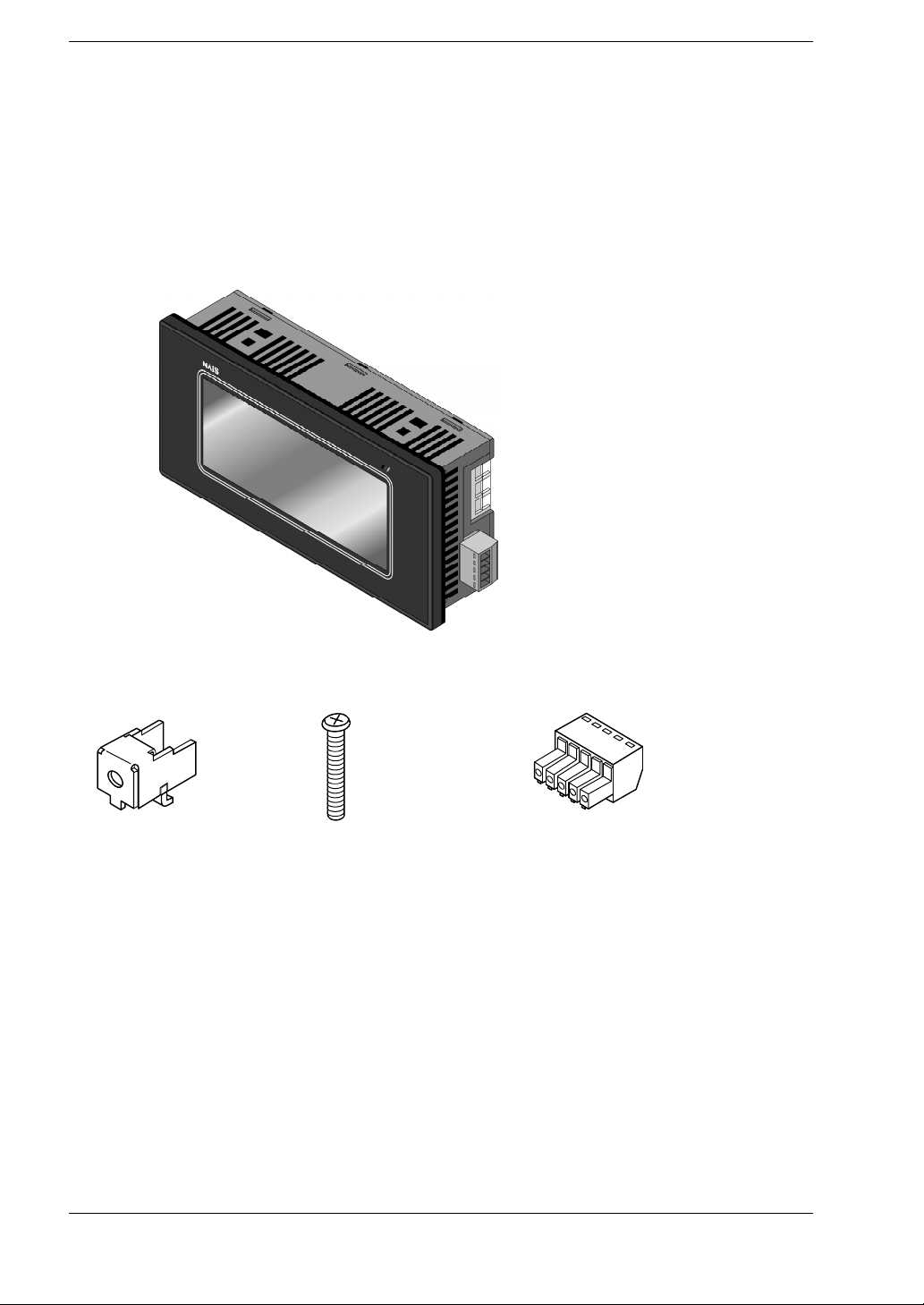
Items Included With the GT10 (AIGT1000B)
Main unit
Set of attachment fittings
Attachment fittings x 4 Attachment screws x 4
Front panel protective sheet
There is a front panel protective sheet,
available as an optional product, attached
to the front panel of the unit.
Installation instructions
Please read these instructions carefully before using the product.
Communication connector
Waterproof packing
One piece of waterproof packing
has been attached to unit.
xi

CAUTION
There is a film over the front panel protective sheet. Remove this film
•
when using the unit. For instructions on removing the film, see page
95.
Front panel protective sheets for replacement are available as a
•
separate purchase (AIGT180). Please see page xvii.
Waterproof packings for replacement are available as a separate
•
purchase (AIGT181). Please see page xvii.
GT10Confirming the Package Contents
xii
GT10
Confirming the Package Contents
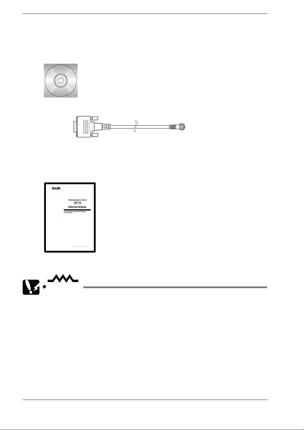
Items Included With the Terminal GTWIN English- language version
(AIGT8001)
Terminal GTWIN CD- ROM
Screen Transfer Cable (AFC8503)
AFC8503
(3 m/9.84 ft)
Software usage license agreement and user card
Read the “Software usage license agreement” carefully, and fill in the user card. Please
return the user card to Matsushita.
GT10 Technical Manual
This is the manual you are currently reading. It contains instructions on installing and
booting GTWIN. Please read it carefully before using your product.
CAUTION
About the software usage license agreement and user card
Before using GTWIN, read the “Software usage license agreement”
•
carefully.
The license agreement comes as a set with the user card. Fill in the
•
user card, and return it to Matsushita. The user card is necessary in
order to obtain support services such as future version upgrades and
technical support. Don’t forget to return the card in order to be
eligible for such services.
The serial number needed in order to install GTWIN is found on the
•
user card. Please make a copy of it before returning the card, and
keep it in a safe place.
xiii
GT10Confirming the Package Contents
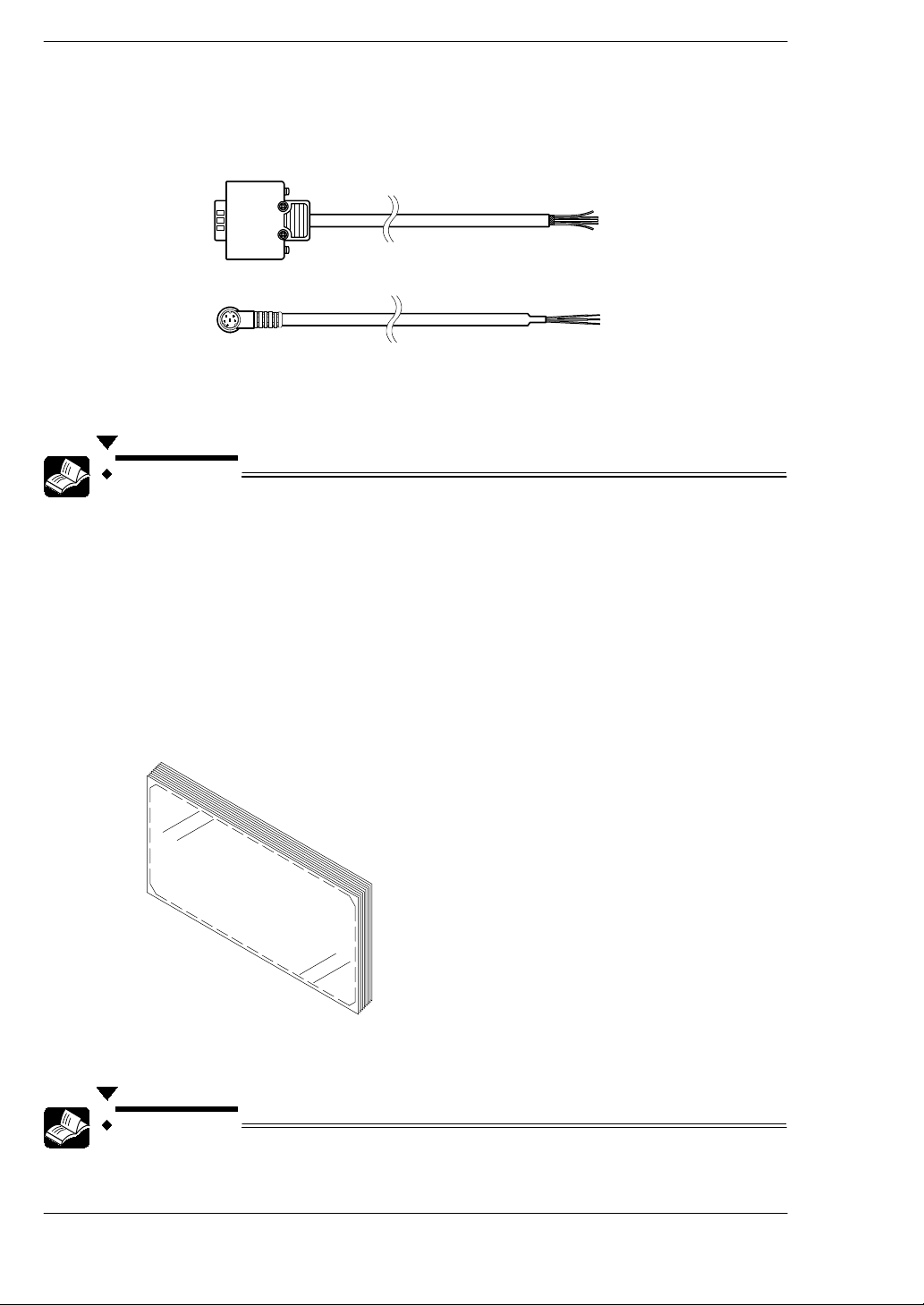
Items Included With the PLC Connection Cable (AIGT8192 / AIP81842)
Cable
One of the following two cables has been included with the product you have purchased.
AIP81842
(2 m/6.56 ft)
AIGT8192
(2 m/6.56 ft)
Wiring diagram
The package includes a diagram that shows the internal wiring of the cables pictured
above.
REFERENCE
For information on connecting and wiring the cables shown above and
the PLC, please refer to page 35, Chapter 4, “Connecting and
Communicating With the PLC”.
Items Included With the Front Panel Protective Sheet (AIGT180)
Front panel protective sheet
In order to protect the touch panel on the GT10 and keep it clean, one front panel
protective sheet is included when the unit is shipped. If this front panel protective sheet
is dirty or has become worn, it should be replaced. Replacement sheets are sold
separately, in packages of ten.
Installation instructions
Please read these instructions carefully before installing the product.
REFERENCE
xiv
For information on replacing the front panel protective sheet, please
refer to page 95.
GT10
,
3
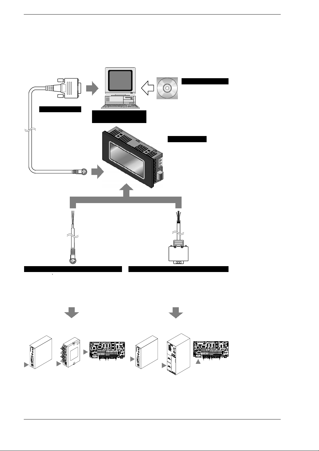
GT10 System Configuration
The following devices are necessary in order to use the GT10.
Screen creation tool
Terminal GTWIN
English-language version
Windows 95/98/2000/NT supported
Connecting cable
Screen transfer cable
D-sub 9-pin mini-DIN 5- pin
(3 m/9.84 ft)
Product No.: AFC8503
* One cable is included
with GTWIN English - language version.
Commercially available
personal computer
GTWIN CD-ROM
Screen transfer cable (AFC8503)
GT10 Technical Manual included as
accessory
Product No.: AIGT8001
Main unit
GT10
STN monochrome liquid crystal display
Product No.: AIGT1000B
GT10 System Configuration
Communication cable
PLC connecting cable (1)
For connection to TOOL port of FP0 / FP2 /
FP2SH / FP - M
Mini-DIN 5- pin loose - wire cable
(2 m/6.56 ft)
Product No.: AIGT8192
Connecting to the TOOL port of the FP0 /
FP2 / FP2SH / FP- M
Communication cable
PLC connecting cable (2)
For connection to COM. port of FP1 / FP2 / FP2SH / FP - M /
FP10SH, TOOL port of FP10SH, and computer communication unit
of FP2 / FP3
D-sub 9-pin loose - wire cable (2 m/6.56 ft)
Product No.: AIP81842
Connecting to the COM. port of FP1 / FP2 / FP2SH / FP - M / FP10SH
TOOL port of FP10SH, and computer communication unit of FP2/FP
xv

CAUTION
Connecting to the COM. port of the FP0
Because connecting the unit to the COM. port of the FP0 requires a
loose- wire connection, this cable is not available. For more detailed
information, please see “Connecting the FP0” on page 37.
GT10GT10 System Configuration
xvi
GT10
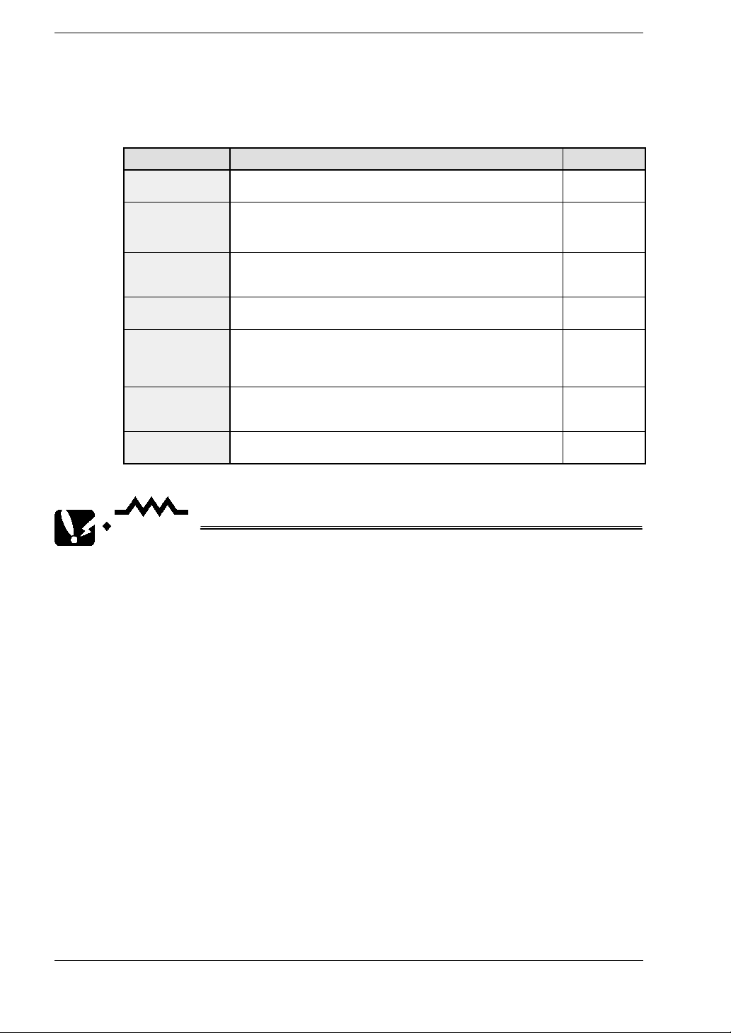
Products for the GT10 Series
Products types
Item Name Contents Product No.
GT10 main unit
Terminal GTWIN
English-language
version
Screen transfer
cable
PLC connecting
cable (1)
PLC connecting
cable (2)
Front panel
protective sheet
Waterproof
packing
Programmable display unit
GT10 main unit
- “Terminal GTWIN” English-language screen creation tool
(CD-ROM)
- Set of GT10 Technical manuals (English)
Cable for transferring cable between GTWIN and GT10
(included with Terminal GTWIN English- language version)
(3 m/9.84 ft)
For connection to TOOL port of FP0 / FP2 / FP2SH / FP - M
Mini-DIN 5- pin loose - wire cable (2 m/6.56 ft)
For connection to COM. port of FP1 / FP2 / FP2SH / FP - M /
FP10SH, TOOL port of FP10SH, and computer communication
unit of FP2 / FP3
D-sub 9-pin loose - wire cable (2 m/6.56 ft)
Front panel protective sheet for GT10 (for replacement).
Teninset.
* 1 sheet included with GT10 when shipped.
Waterproof packing for GT10 (for replacement). Ten in set.
* 1 piece included with GT10 when shipped.
Products for the GT10 Series
AIGT1000B
AIGT8001
AFC8503
AIGT8192
AIP81842
AIGT180
AIGT181
CAUTION
Connecting to the COM. port of the FP0
•
Because connecting the unit to the COM. port of the FP0 requires a
loose- wire connection, this cable is not available. For more detailed
information, please see “Connecting the FP0” on page 37.
About the manual packed with the Terminal GTWIN English - language
•
version
The manual you are currently reading is included as an accessory
with the Terminal GTWIN English - language version. This manual
contains information only on procedures such as installing GTWIN.
For detailed information on operating GTWIN, please refer to the Help
function in the software.
xvii
GT10An Overview of GT10 Functions
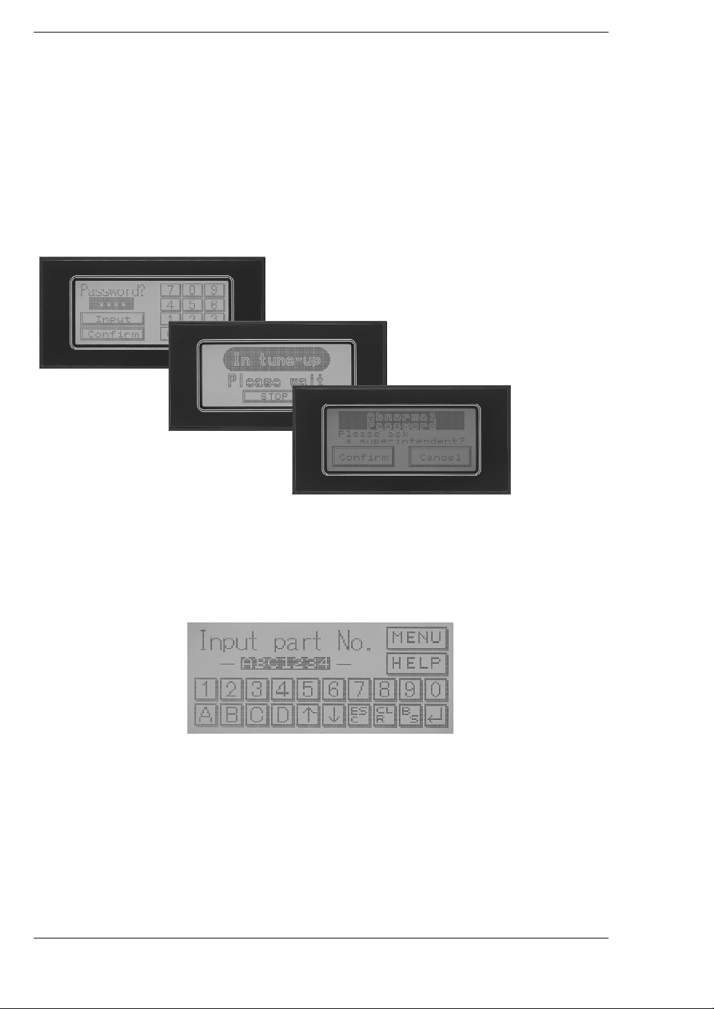
An Overview of GT10 Functions
3 colors can be displayed, to reflect the status
Various messages and graphics can be displayed on the liquid crystal display screen,
which measures 160 x 64 dots, as well as lamps, internal PLC data, graphs, clocks, and
other information.In addition, backlightingis available in three colors,green, orange, and
red, so that information can be color -coded. This makes it easy to grasp information at
a glance.
Green
Orange
Red
High- resolution touch panel provided
A compact touch panel is provided with on-screen switches and a keyboard, letting you
operate the unit simply by touching the screen. This high - resolution touch panel is fitted
with 20 horizontal and 8 vertical segments, so that numerous switches can be used, and
allows maximum flexibility in the switch layout.
xviii
GT10
An Overview of GT10 Functions
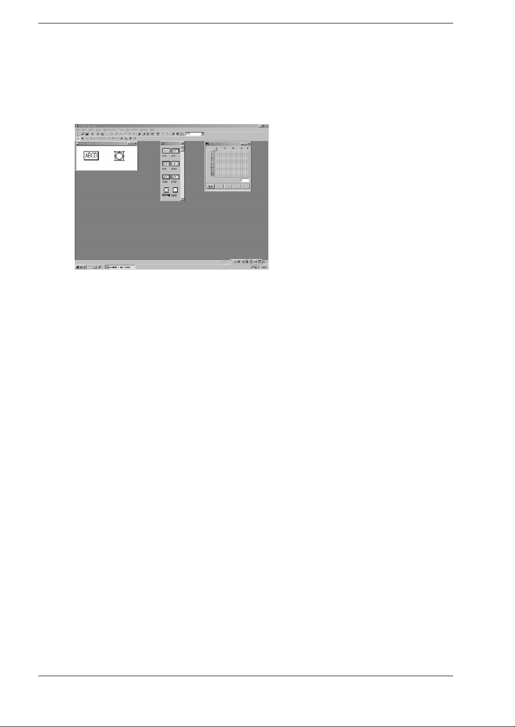
Screens can be created easily, using special tools
Screen contents can be easily created using the dedicated Terminal GTWIN tool (runs
on Windows 95/98/2000/NT). Screens are put together simply by selecting parts from
a library and positioning them in place.
xix
GT10An Overview of GT10 Functions
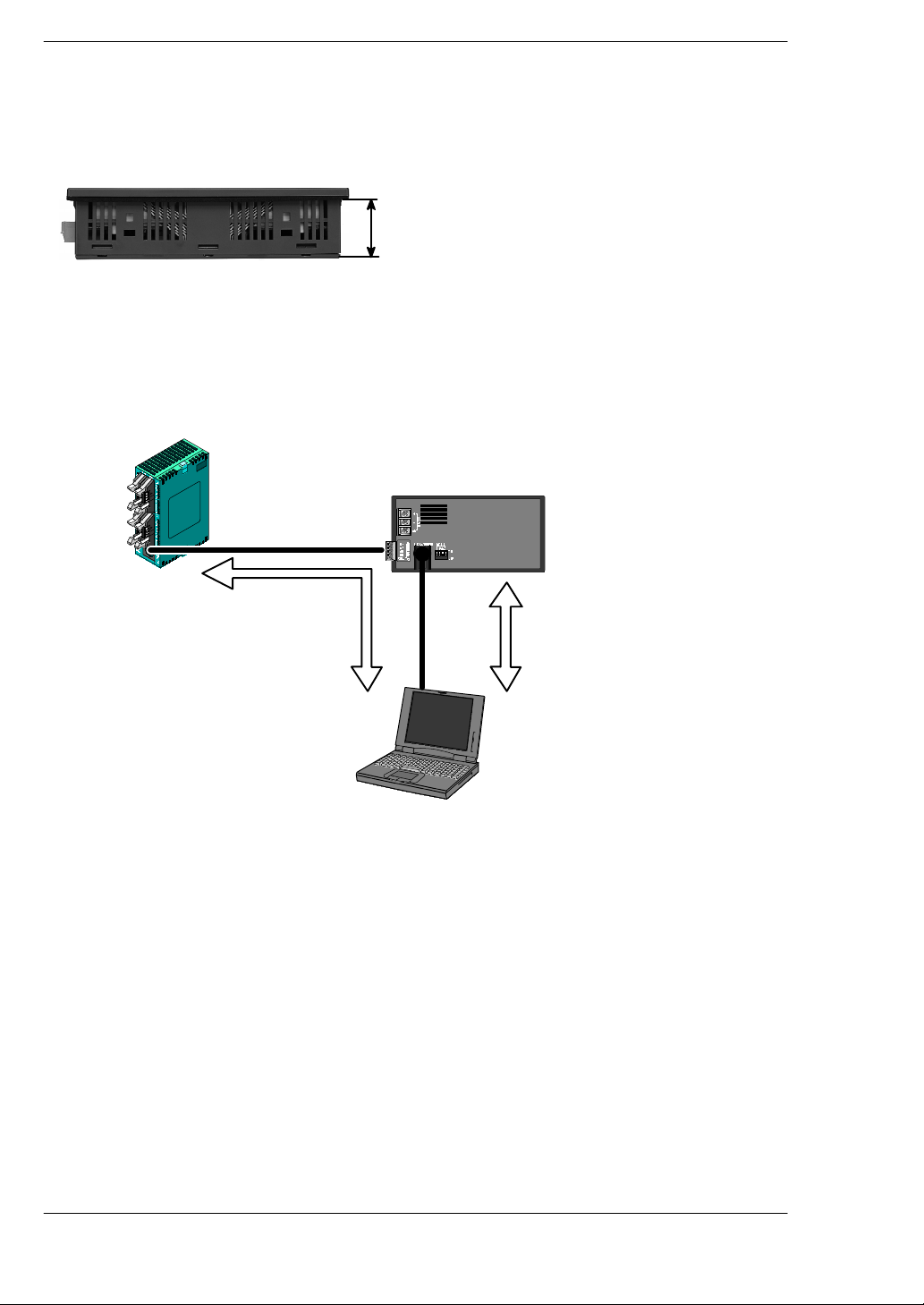
Ultra- thin body is only 32 mm/1.26 inch deep
The in- panel depth is a mere 32 mm/1.26 inch (including the fittings), configuring an
ultra- thin body and taking up a bare minimum of space.
32
mm
/1.26
inch
Through function is convenient for debugging
If connectionsare made asshown inthe diagram, a convenient“through” function makes
it possible to transfer data from the GT10 and carry out PLC debugging at the same time
that communication is going on between the GT10 and the FP series PLC. This
significantly boosts efficiency in the workplace.
PLC
GT10
Cable connected to
COM or TOOL port
of PLC
PLC debugging
The FPWIN GR and NPST - GR
can be booted on the computer
being used to edit GT10 screens,
and PLC programs edited and
monitored through the GT10.
Screen
transfer
cable
AFC8503
Screen data
being sent
and received
Screen creation tool GTWIN
FP series programming tool
FPWIN GR
Personal computer
Maintenance is easier than ever before
LEDs are used for backlighting, eliminating the fuss and bother of replacement. Screen
data is saved to an F -ROM, while other data is backed up by an internal secondary
battery, sono battery replacementis needed. Thisassures long-term, stable usewithout
worrying about lost data.
xx

GT10
Safety Precautions
Safety Precautions
Before installing, operating, servicing or inspecting this product, please make sure you
have read this manual and the installation instructions, and make sure the product is
used correctly.
This manual uses two safety standard levels: “WARNING” and “CAUTION”.
WARNING
Erroneous handling of an item marked with this label can cause fatal or critical injury to
the user.
If this product is used in applications where accidents involving
•
bodily injury and/or significant damage may be conceivable,
measures should be taken to ensure adequate safety, such as the
use of duplicate safety mechanisms.
The functions of the GT10 should not be used to design systems
•
which may pose a threat to human life or which may cause severe
injury or damage. Designs should include safety mechanisms for
use in the event that switch functions malfunction.
Do not use this product in an environment where combustible gases
•
are present. (This can cause explosion.)
This product contains a secondary battery (lithium and vanadium).
•
Do not dispose of it by incineration. (This can cause it to explode.)
CAUTION
Erroneous handling of an item marked with this label can cause injury to the user, or
physical damage to property.
This product should not be used outside of the stated specifications
•
ranges for ratings, service life, configuration factors and other
elements. (This can cause abnormal generation of heat and
smoke.)
The operational force of the touch panel should be kept to 0.98 N or
•
lower. Operating the touch panel at a higher force could cause
damage.
Never touch terminals while the power supply is on. (This can cause
•
electric shock.)
Never disassemble or alter this product. (This can cause electric
•
shock and smoke generation.)
xxi

GT10Safety Precautions
Special Items
Maximum attention has been given to quality control of this product; however:
(1) In order to prevent, as much as possible, unexpected situations not covered by these
specifications, please consult us regarding your product’s specifications and demands,
as well as this unit’s operating conditions and installation details.
(2) To avoid the unlikely event of a situation attributed to inferior quality of the unit which
has serious adverse affects on persons or property, the numeric values for guaranteed
characteristics and performance noted in this specifications manual should be
considered the minimum necessary values. As the manufacturer of this unit, we
recommend incorporating additional safety measures such as duplicate circuits
wherever possible.
(3) The quality of this product is guaranteed for one year after purchase, and this
guarantee is limited to the range of items stated in these specifications. In the case of
a defect in the product which is clearly Matsushita’s responsibility, we will offer a
replacement unit or replacement of the defective part(s) of the unit and we will repair the
unit promptly at the place of purchase. The following are not included in the warranty:
1. Other damage resulting from damage to or defects in the supplied product.
2. Problems caused by conditions other than those noted in these specifications
involving use, storage, or shipment (transport) after product delivery.
3. Developments which were unforeseeable given the technology in practical use prior
to product delivery.
4. Earthquake, flood, fire, war, and damage due to other naturally occurring events or
human disasters for which Matsushita bears no responsibility.
xxii

Chapter 1
Specifications
This chapter contains the names and specifications of the various parts of the GT10, as
well as a table of functions, wiring diagrams, and dimensions.
1.1 GT10 Specifications 3................................
1.1.1 General Specifications 3......................
1.1.2 Display 3....................................
1.1.3 Functions 4..................................
1.1.4 Touch Key 4.................................
1.1.5 Memory (1) 4................................
1.1.6 Memory (2) 4................................
1.1.7 Interface 5..................................
1.2 Names and Functions of Parts 6.......................
1.2.1 GT10 (front) 6...............................
1.2.2 GT10 (rear) 6................................
1.2.3 Names and Functions of Parts 7...............
1.3 Internal Wiring Connections for Ports 9.................
1.3.1 COM. Port 9.................................
1.3.2 TOOL Port 9.................................
1.3.3 Power Supply Terminals 10....................
1.4 Dimensional Outline Diagram 11.......................
1.4.1 GT10 Dimensional Outline Diagram 11..........
1.4.2 Panel Cutout Dimensional Outline Diagram 12...

GT10Specifications
2
1.1 GT10 Specifications
1.1.1 General Specifications
Item Specifications
Rated voltage
Operating voltage range
Power consumption
Ambient temperature
Ambient humidity 20% RH to 85% RH (non condensing)
Storage temperature
Storage humidity 10% RH to 85% RH (non condensing)
Vibration resistance
Shock resistance 98 m/s2min., 4 times on 3axes
Noise immunity
Static noise resistance 5,000 V min. (panel display)
Protective construction
Mass Approx. 260 g/9.171 oz
24V DC
21.6 to 26.4V DC
5 W max.
0°Cto40°C/32°F to 104°F (25V DC max. if installed horizontally)
-20°Cto60°C/-4°F to 140°F
10Hz to 55 Hz (1 - minute cycle)
Amplitude: 0.75 mm, 10 min on 3axes
1,000 V [p - p] min., pulse width 50 ns, 1 μs between power supply terminals (based
on noise simulator)
IP65 (in initial status)
Dustproof and drip-proof from front panel only (packing used on panel contact surface)
* When reattaching, replace waterproof packing.
SpecificationsGT10
1.1 GT10 Specifications
1.1.2 Display
Item Specifications
Display STN monochrome LCD
Resolution 160 (W) x 64 (H) dots
Displayable area 92.8 (W) x 37.1 (H) mm 3.65(W) inch x 1.46 (H) inch
LCD life
Backlight 3-color LED backlight (green, red, orange) * No replacement necessary
Average: 50,000 hours (at normal temperature of 25°C)
3
1.1 GT10 Specifications
1.1.3 Functions
Item Specifications
1/4 width, half width, full width characters
Character sizes
Character types Alphanumeric characters
Graphics
Number of screens
Part functions Messages, lamps, switches, data, bar graphs, clocks, keyboard
Clock functions Clock built into main unit (can also be displayed with reference to PLC clock)
Contrast adjustment Contrast can be adjusted using touch panel operation (10 stages)
Automatic communication
settings
Debugging functions
Screen creation
Half width and full width characters can be displayed at same width, doubled width,
or quadrupled width
(Widths of 2 x 2 times or more can be displayed in high - quality font display.)
Straight lines, continuous straight lines, squares, circles, ovals, arcs, elliptic arcs, fan
shapes, elliptic fan shapes, beveled squares, bitmaps
Approx. 160 screens
Screen numbers that can be set: Base screens No. 00 to FF (HEX)
(Number of screens that can be registered varies depending on registered contents.)
Settings for communication between dedicated software and PLC set automatically
by connecting cable
Through function (PLC can be debugged from personal computer by connecting
computer to TOOL port and PLC to COM. port)
Dedicated software Terminal GTWIN used.
Applicable OS: Windows 95/98/2000/NT (Ver. 4.0 or later )
GT10Specifications
1.1.4 Touch Key
Item Specifications
Touch key resolution
Touch key operation
Touch key life
20 (W) x 8 (H)
0.98 N max.
6
Min. 10
1.1.5 Memory (1)
Screen data and GTWIN Configuration Settings data
Item Specifications
Memory type F-ROM
Memory capacity
384 kbytes
1.1.6 Memory (2)
Clock data and PLC device storage data (24 words max.)
Item Specifications
Memory SRAM
Memory backup
Backed up by internal secondary battery (charged when power is on)
(Note) When using, set operation mode switch on back of main unit to “ON” position.
4
1.1.7 Interface
Item Specifications
Communications ratings Conforms to RS232C
Baud rate: 9600, 19200, 38400, 57600, 76800, 115200 bits/s
Data bits: 7 or 8 bits
Parity: None, Odd, Even
Stop bits: 1 bit
Baud rate: 9600, 19200, 115200 bits/s
Data bits: 8 bits
Parity: None, Odd, Even
Stop bits: 1 bit
Mini-DIN (5-pin)
COM.
Port
TOOL
port
Conditions for
communications with
external devices
Protocol FP series supported/general - purpose RS232C supported
Connector Connector terminal base (5 - pin)
Communications ratings Conforms to RS232C
Conditions for
communications with
external devices
Protocol Dedicated protocol
Connector
SpecificationsGT10
1.1 GT10 Specifications
5
1.2 Names and Functions of Parts
y
1.2 Names and Functions of Parts
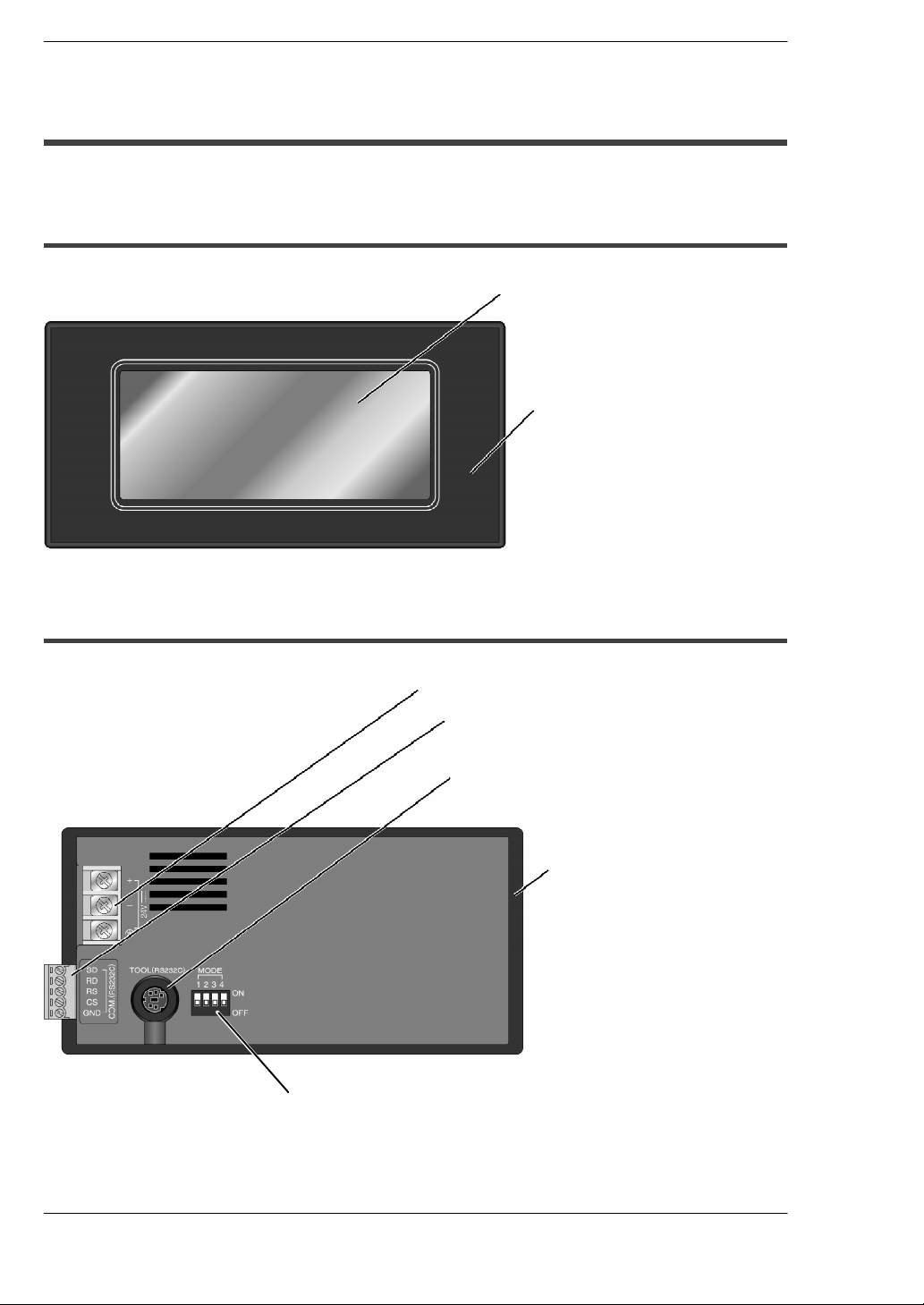
1.2.1 GT10 (front)
Liquid crystal display panel
1
●
(touch panel)
2
Front panel protective sheet
●
(one sheet is attached to unit when
unit is shipped)
GT10Specifications
1.2.2 GT10 (rear)
3
Power supply terminal
●
4
●
5
●
Operation mode setting switches
6
●
COM. port (PLC/external device connection port)
(1 communication connector provided as accessor
when unit is shipped)
TOOL port (connection port for GTWIN
screen creation tool)
7
Waterproof packing
●
(1 piece is attached to unit when
unit is shipped)
6
 Loading...