

Page 1
Programmable Display GT01 Technical Manual
ARCT1F381E ’03.4
http://www.naisplc.com/
Programmable Display
GT01
Technical Manual
■ Applicable Product
• GT01
This manual was created using Adobe Acrobat.
Adobe, the Adobe logo, and Acrobat are trademarks
of Adobe Systems Incorporated.
Page 2

SAFETY PRECAUTIONS
[ALWAYS OBSERVE THESE PRECAUTIONS]
Before installing, operating, servicing or inspecting this product, please make sure
you have read this manual and the explanations of how procedures are carried out,
and make sure the product is used correctly.
This manual uses two safety standard levels: “WARNING” and “CAUTION”.
WARNING
Erroneous handling of an item marked with this label can cause fatal or critical
injury to the user.
•
If this product is used in applications where accidents involving bodily
injury and/or significant damage may be conceivable, measures should
be taken to ensure adequate safety, such as the use of duplicate safety
mechanisms.
•
The functions of the GT main unit should not be used to design systems
which may pose a threat to human life or which may cause severe injury
or damage. Designs should include safety mechanisms for use in the
event that switch functions do not function correctly.
•
Do not use this product in an environment where combustible gases are
present. This can cause explosion.
•
Do not dispose of it by incineration. This can cause it to explode.
CAUTION
Erroneous handling of an item marked with this label can cause injury to the
user, or physical damage to property.
•
This product should not be used outside of the stated specifications
ranges for ratings, service life, configuration factors and other
elements. This can cause abnormal generation of heat and smoke.
•
The operational force of the touch panel should be kept to 0.98 N or
lower. Operating the touch panel at a higher force could cause damage.
•
Never touch terminals while the power supply is on. This can cause
electric shock.
•
Never disassemble or alter this product. This can cause electric shock
and smoke generation.
Page 3

i
How This Manual Is Configured
GT series Main Unit
Before Using the GT series
This section describes items that should be confirmed and precautions that should
be observed before the GT series are used.
Chapter 1. Specifications
This chapter contains the names and specifications of the various parts of the GT
series, as well as a table of functions, wiring diagrams, and dimensions.
Chapter 2. Installation and Wiring
Thischapter explainshow theGT series should be installedand howwiring should be
connected.
Chapter 3. Setup
Thischapter describes the setup procedures necessary when using the GT series for
the first time.
Chapter 4. Connecting and Communicating with the PLC
This chapter explains how to connect the GT series to the PLC and the FP series by
Matsushita, and how to set up communications between the units.
Chapter 5. GT series Configuration Settings
This chapter describes the configuration settings for the GT series, and how they
should be entered.
Chapter 6. Using the Various Functions
Functions such as switching GT series screens, backlighting, and buzzer control are
explained here.
Chapter 7. Servicing and Maintenance
This chapter describes servicing and maintenance procedures for the GT series, as
well as how optional items are handled.
Chapter 8. Troubleshooting
This explains what to do if there appears to be something wrong with the GT series,
or an error occurs.
Chapter 9. Documentation
Thissection includesBIN/HEX/BCD codecorrespondence tables, ASCII code tables,
cable specifications, and other information.
Page 4

GT seriesTable of Contents
ii
Table of Contents
GT Series Main Unit
Before Using the GT
GT Series Usage Procedures ix..............................................
Confirming the Package Contents xi..........................................
GT Series System Configuration xiv..........................................
Products for the GT Series xv................................................
An Overview of GT01 Functions xvi...........................................
Chapter 1 Specifications
1.1 GT01 Specifications 3..................................................
1.1.1 General Specifications 3........................................
1.1.2 Display 3......................................................
1.1.3 Functions 4....................................................
1.1.4 Touch Key 4...................................................
1.1.5 Memory (1) 4..................................................
1.1.6 Interface 5....................................................
1.2 GT01 Names and Functions of Parts 6...................................
1.2.1 GT01 (front) 6.................................................
1.2.2 GT01 (rear) 6..................................................
1.2.3 Names and Functions of Parts 7.................................
1.3 Internal Wiring Connections for Ports 8...................................
1.3.1 COM. Port 8...................................................
1.3.2 TOOL Port 8...................................................
1.4 Dimensions 9.........................................................
1.4.1 GT01 Dimensions 9............................................
1.4.2 GT01 Panel Cutout Dimensions 10...............................
Chapter 2 Installation and Wiring
2.1 Installation 13.........................................................
2.1.1 Installation Environment 13......................................
2.1.2 GT01 Installation Method 15.....................................
2.2 Wiring the Power Supply 16.............................................
2.2.1 Wiring the Power Supply 16.....................................
Page 5

Table of Contents
GT series
iii
2.3 Wiring the COM. Port 17................................................
2.3.1 Wiring the COM. Port 17........................................
2.3.2 Wiring Method 17..............................................
2.3.3 Precautions Concerning Wiring 18................................
Page 6

GT seriesTable of Contents
iv
Chapter 3 Setup
3.1 Setup Procedure for the GT01 21........................................
3.1.1 Setup Procedure 21............................................
3.2 Setting the Basic Communication Area Between the GT01 and PLC 24.......
3.2.1 What is the Basic Communication Area? 24.......................
3.2.2 GT01 Basic Communication Area Map 26.........................
Chapter 4 Connecting and Communicating with the PLC
4.1 Connecting the FPΣ 29.................................................
4.1.1 Connecting to the TOOL Port 29.................................
4.2 Connecting the FP0 30.................................................
4.2.1 Connecting to the TOOL Port 30.................................
4.3 Connecting the FP2/FP2SH 31..........................................
4.3.1 Connecting to the TOOL Port 31.................................
4.4 Connecting the FP-M 32................................................
4.4.1 Connecting to the TOOL Port 32.................................
4.5 Automatic Communication Settings Function 33............................
4.6 Through Function 35...................................................
Chapter 5 GT01 Configuration Settings
5.1 GT01 Configuration Settings 39..........................................
5.1.1 Two Types of GT01 Configuration Settings 39......................
5.2 Entering Configuration Settings from GTWIN Screen Creation Tool 40........
5.2.1 Opening the GT Configuration Settings 40.........................
5.2.2 GT Configuration Settings: “Basic Setup” 41.......................
5.2.3 GT Configuration Settings: “Communication Parameters” 43.........
5.2.4 GT Configuration Settings: “Auto-Paging” 46......................
5.2.5 GT Configuration Settings: “Startup Screen Settings” 48.............
5.2.6 GT Configuration Settings: “Setup” 50............................
5.3 Entering Configuration Settings from the GT01 Main Unit 52.................
5.3.1 What is the System Menu? 52...................................
5.3.2 Bringing Up the System Menu 52.................................
5.3.3 Setting Mode: “Communication Parameters”
(COM. Port / TOOL Port) 53.....................................
5.3.4 Setting Mode: “Liquid Crystal Display Contrast Adjustment” (Contrast)5
5
Page 7

Table of Contents
GT series
v
5.3.5 Setting Mode: “Memory Initialization” (Clear Memory) 56............
5.3.6 Test Mode: “Self-Diagnosis” 57..................................
5.3.7 Inhibiting the System Menu Display 58............................
Page 8

GT seriesTable of Contents
vi
Chapter 6 How the Various Functions Are Used
6.1 Switching Screens 61..................................................
6.1.1 Switching the Screen from the PLC 61............................
6.1.2 Switching the Screen with the GT Main Unit 62.....................
6.2 Basic Communication Area to PLC and Bit Device Functions (GT01) 67.......
6.2.1 Bit Device Functions 67.........................................
Chapter 7 Servicing and Maintenance
7.1 Replacing the Front Panel Protective Sheet 71.............................
7.1.1 About the Front Panel Protective Sheet 71........................
7.1.2 Replacing the Front Panel Protective Sheet 71.....................
7.2 Replacing the Waterproof Packing 72.....................................
7.2.1 About the Waterproof Packing 72.................................
7.2.2 Replacing the Waterproof Packing 72.............................
Chapter 8 Troubleshooting
8.1 What to Do If Something Unusual Occurs (GT01) 75.......................
8.2 Error Codes and How to Handle Them 78.................................
8.2.1 About Error Codes 78...........................................
8.2.2 GT Series Error Codes 78.......................................
8.2.3 PLC Error Codes 79............................................
8.3 Table of Screen Messages 80...........................................
8.3.1 Table of GT01 Screen Messages 80..............................
Appendix Information
A.1 BIN/HEX/BCD Code Correspondence Table 83............................
A.2 ASCII Code Table 84...................................................
A.3 Cable Specifications 85.................................................
A.3.1 PLC Communication Cable: Mini-DIN 5-pin Loose-Wire
(AIGT8142) 85.................................................
Page 9

GT series
vii
Before Using the GT
This section describes items that should be confirmed and precautions that should be
observedbefore the GTseriesis used. Makesureyou read thissectionbefore using the
GT series.
Page 10

GT series
viii
Page 11

GT Series Usage Procedures
GT series
ix
GT Series Usage Procedures
If you are using the GT series for the first time, please follow the procedure outlined
below.
Procedure For Using the GT series
1. Confirm the items included with the product. page xi
Please confirm that all of the items have been included with the product you have
purchased. Products are carefully checked before being shipped, but if you do find
anything missing, please contact your dealer.
2. Install and wire the main unit.
page 13
Install the main unit, and connect the power supply, PLC connection cable and other
wiring. When installing and wiring the product, carefully read the explanation on pages
13 to 15 concerning the installation environment,and make sure the productis installed
correctly, in an appropriate environment. For information on connecting the product to
the FP series PLC, and on entering communications settings, please see page 29 and
subsequent pages.
3. Set up the main unit.
page 21
When the product is shipped from the factory,it is set up with specifications that enable
connection to the FP series PLC. If you plan to use the product without changing these
settings,nosetupisrequired,butifyouplantochangethesettings,youwillneedtofollow
thesetupprocedureoutlinedonpage21andsubsequent pages.Particularlywithregard
to the basic communication area to the PLC and other devices, please confirm the
settings carefully and change only those that are necessary.
J Main cases in which setup is necessary
·
When the device being connected is a general-purpose serial device (such as
a computer or microcomputer board)
·
When the basic communication area for the device is different from that
set when the product is shipped
4. Check communication with the external device (PLC, etc.).
page 30
Check the connections and communication with the external device. Connections and
communication with devices in the FP series PLC vary depending on the device, so
check the information on page 30 and subsequent pages.
5. Enter the operating environment settings.
page 39
In addition to the setup described at step 4, various detailed settings can be entered for
the GT01 operating environment. Enter any necessary operating environment settings,
referring to page 39 and subsequent pages.
Page 12

GT seriesGT Series Usage Procedures
x
6. Install the screen creation tool.
Install the Terminal GTWIN screen creation tool in the personal computer.
7. Create the screen contents.
Create the screen contents using the Terminal GTWIN screen creation tool, and send
the screen to the GT main unit. For information on creating screens and on operating
GTWIN, please refer to the Help function that comes with GTWIN.
8. Test the operation.
Connect the GT main unit containing the screen data to an external device (PLC or
general-purpose serial device), and check the operation contents.
Page 13
Confirming the Package Contents
GT series
xi
Confirming the Package Contents
Checkto make sure the necessary itemshave been included with the product youhave
purchased.
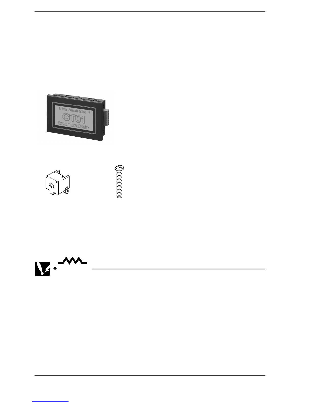
Items Included with the GT01 (AIGT0030B1, AIGT0030H1)
Main unit
Set of attachment fittings
Attachment fittings x 4 Attachment screws x 4
Installation instructions
Please read these instructions carefully
before using the product.
Waterproof packing
One piece of waterproof packing has
been attached to unit.
Thefollowing maintenancepartisavailable: AIGT081 (10 piece set)
CAUTION
•
There is a film over the front panel protective sheet. Remove this film
when using the unit. For instructions on removing the film, see page
71.
•
Front panel protective sheets for replacement are available as a
separate purchase (AIGT083). Please see page xv.
•
Waterproof packings for replacement are available as a separate
purchase (AIGT081). Please see page xv.
Page 14
GT seriesConfirming the Package Contents
xii
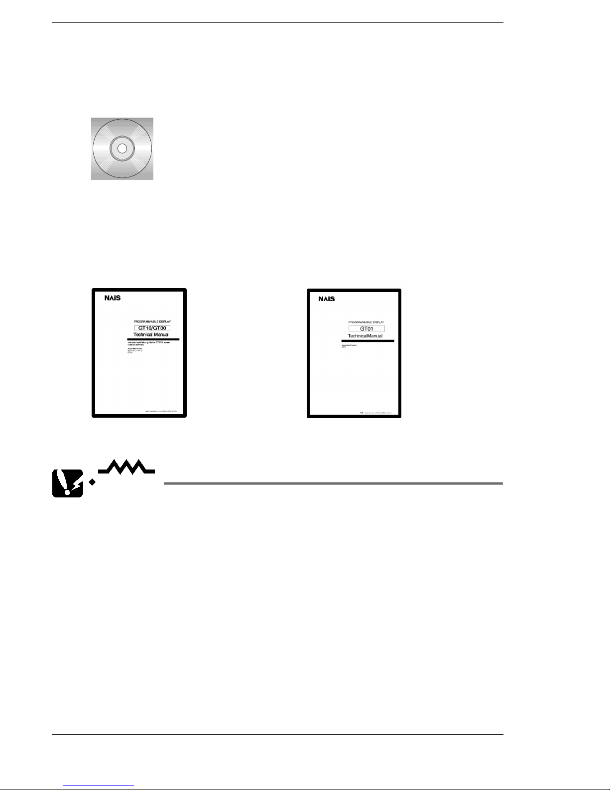
Items Included with the Terminal GTWIN English-language version
(AIGT8001V2)
Terminal GTWIN CD-ROM
Software usage license agreement and user card
Readthe “Software usagelicense agreement” carefully, and fill in the user card. Please
return the user card to Matsushita.
GT10/GT30 Technical Manual GT01 Technical Manual
This is the manual you are currently reading. It contains instructions on installing and
booting GTWIN. Please read it carefully before using your product.
CAUTION
About the software usage license agreement and user card
•
Before using GTWIN, read the “Software usage license agreement”
carefully.
•
The license agreement comes as a set with the user card. Fill in the
user card, and return it to Matsushita. The user card is necessary in
order to obtain support services such as future version upgrades and
technical support. Don’t forget to return the card in order to be
eligible for such services.
•
The serial number needed in order to install GTWIN is found on the
user card. Please make a copy of it before returning the card, and
keep it in a safe place.
Page 15
Confirming the Package Contents
GT series
xiii
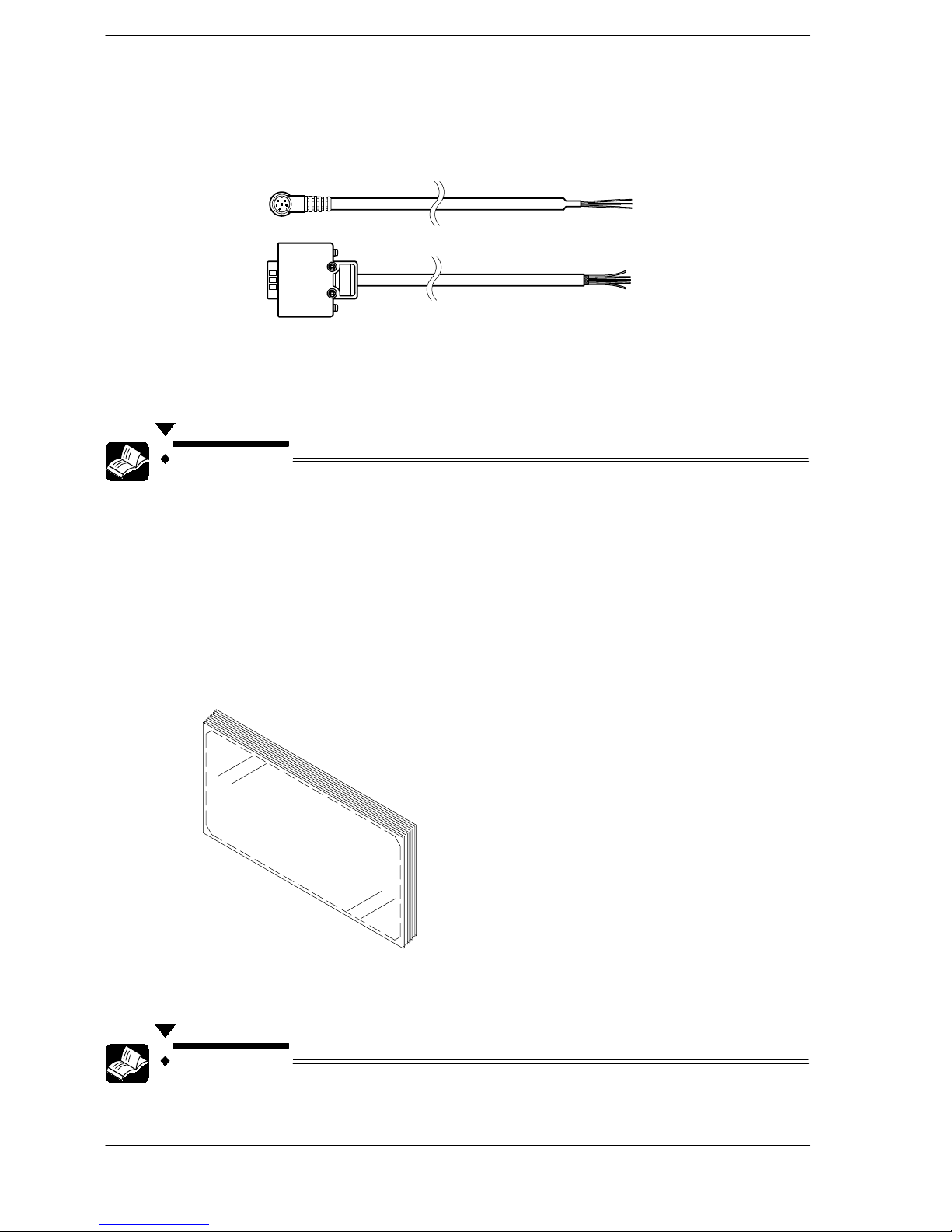
Items Included With the PLC Connection Cable (AIGT8142 / AIP81842)
Cable
Oneofthe following twocableshasbeenincludedwiththe product youhavepurchased.
AIGT8142
(2 m/6.56 ft)
AIP81842
(2 m/6.56 ft)
Wiring diagram
The package includes a diagram that shows the internal wiring of the cables pictured
above.
REFERENCE
For information on connecting and wiring the cables shown above and
the PLC, please refer to Chapter 4, “Connecting and Communicating
with the PLC”.
Items Included with the Front Panel Protective Sheet (AIGT080)
Front panel protective sheet
Optional protective sheets are available to protect and keep the GT series touch panel
clean.Pleaseuseifyouwishtoprotectthefrontpanelfrom dirt and prevent degradation.
Installation instructions
Please read these instructions carefully before installing the product.
REFERENCE
For information on replacing the front panel protective sheet, please
refer to page 71.
Page 16
GT seriesGT Series System Configuration
xiv
GT Series System Configuration
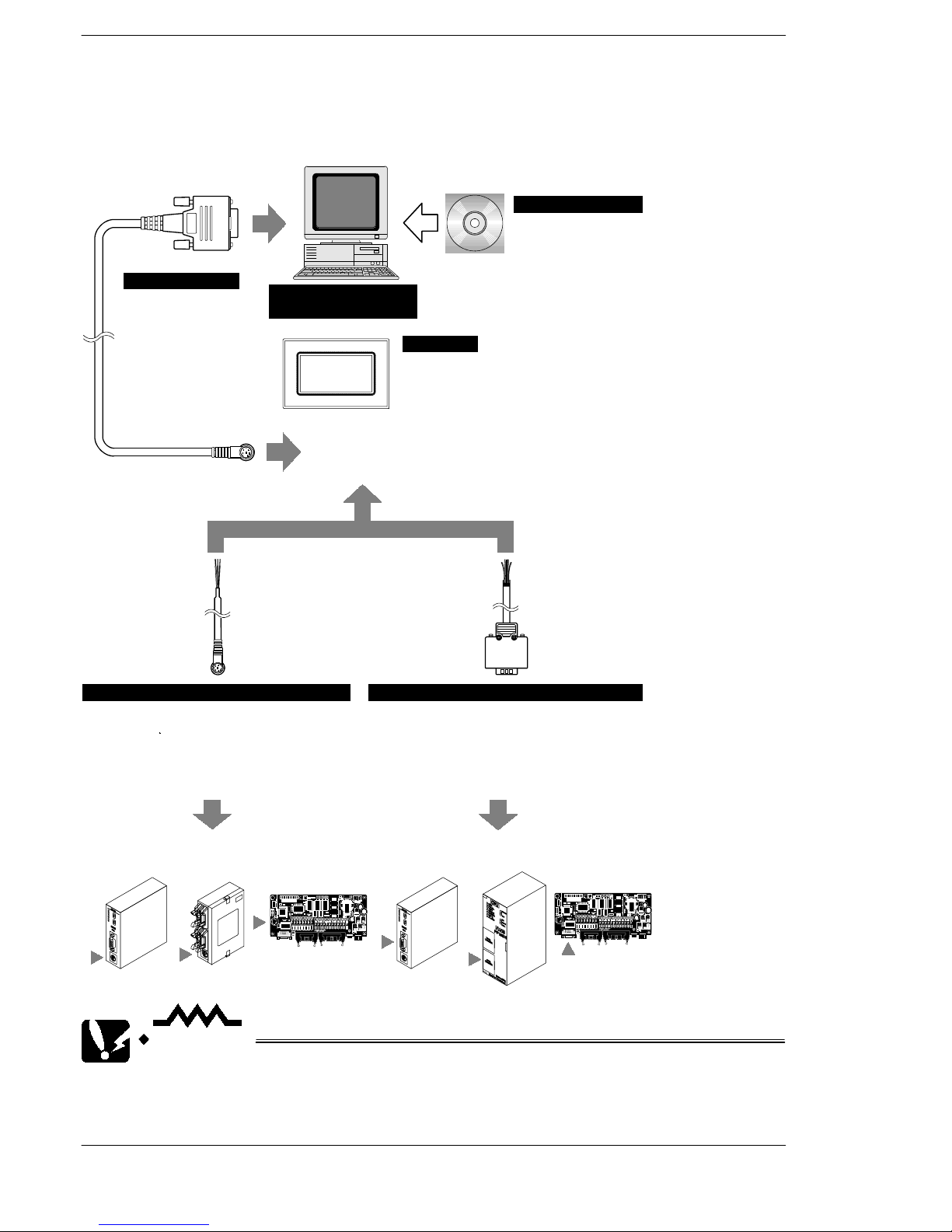
The following devices are necessary in order to use the GT series.
Connecting cable
Screen transfer cable
D-sub 9-pin -
mini-DIN 5-pin
(3 m/9.84 ft)
Product No.: AFC8503
Commercially available
personal computer
Screen creation tool
Terminal GTWIN
English-language version
Windows 95/98/2000/NT supported
GTWIN CD-ROM
Technical Manual included as accessory
Product No.: AIGT8001V2
GT01
STN monochrome liquid crystal display
Product No.: AIGT0030B1, AIGT0030H1
Main unit
Communication cable
PLC connecting cable (1)
For connection to TOOL port of FP0 / FP2 /
FP2SH / FP-M
Mini-DIN 5-pin loose-wire cable
(2 m/6.56 ft)
Product No.: AIGT8192
Connecting to the TOOL port of the FP0 /
FP2 / FP2SH / FP-M
Communication cable
PLC connecting cable (2)
For connection to COM. port of FP1 / FP2 / FP2SH / FP-M /
FP10SH, TOOL port of FP10SH, and computer communication unit
of FP2 / FP3
D-sub 9-pin loose-wire cable (2 m/6.56 ft)
Product No.: AIP81842
Connecting to the COM. port of FP1 / FP2 / FP2SH / FP-M /
FP10SH and computer communication unit of FP2/FP3
CAUTION
Connecting to the COM. port of the PLC
Because connecting the unit to the COM. port of the FPΣ/FP0 requires a
loose-wire connection, this cable is not available.
Page 17
Products for the GT Series
GT series
xv
Products for the GT Series
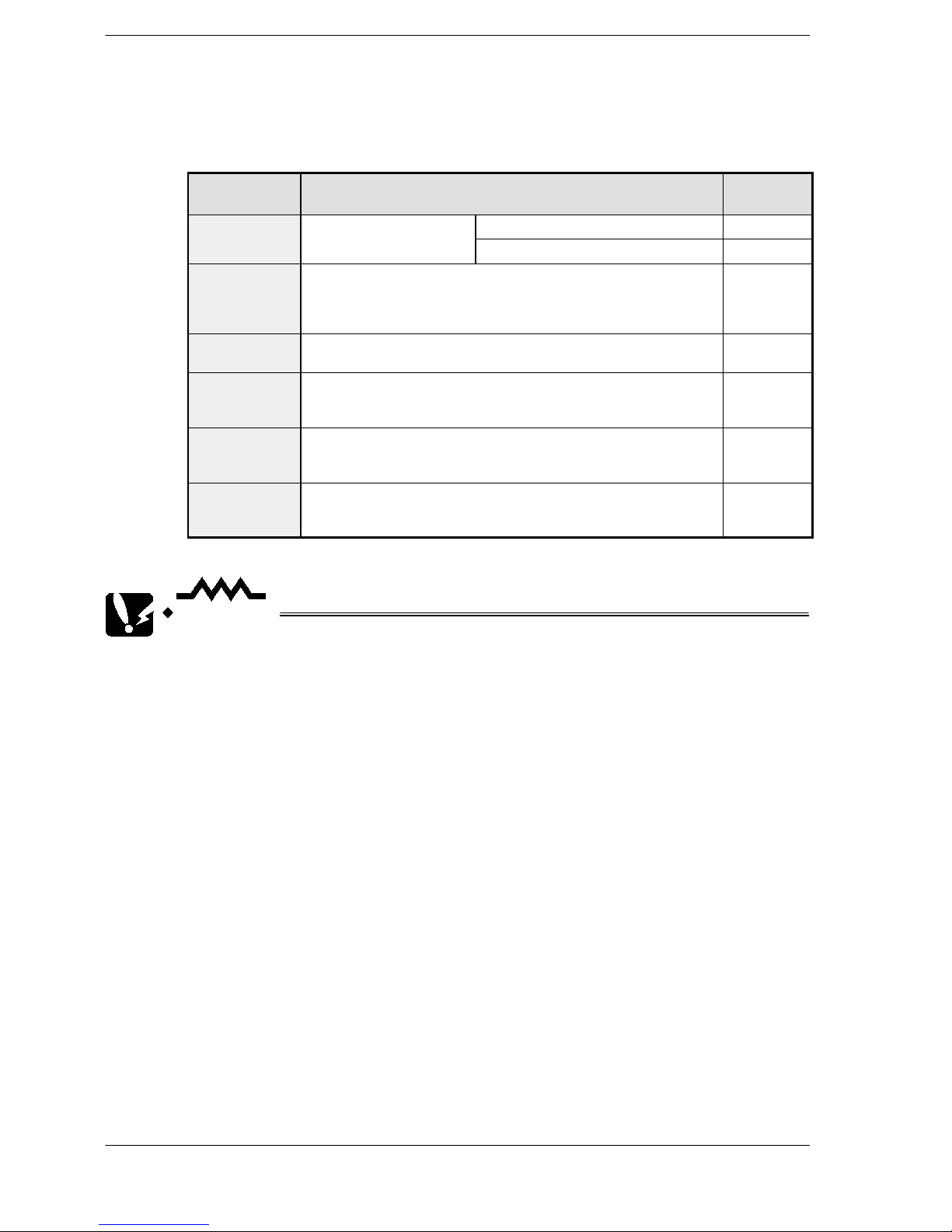
Products types
Item Name Contents
Product
No.
Programmable display unit
RS232C, Black (Charcoal gray) AIGT0030B1
GT01mai
nunit
main unit
RS232C, ashgray AIGT0030H1
Terminal
GTWIN
English- langua
ge version
- “Terminal GTWIN” English-language screen creation tool
(CD-ROM)
- Set of GT01 Technical manuals (English)
AIGT8001V2
Screen transfer
cable
Cable for transferring data between GTWIN and GT (3 m/9.84 ft) AFC8503
PLC
connecting
cable (1)
For connection to TOOL port of FP0 / FPΣ / FP2 / FP2SH / FP-M
Mini-DIN 5-pin loose-wire cable (2 m/6.56 ft)
AIGT8142
PLC
connecting
cable (2)
For connection to COM. port of FP10SH, and other PLC COM. port
D-sub 9-pin loose-wire cable (2 m/6.56 ft)
AIP81842
Front panel
protective
sheet
Front panel protective sheet for GT01 (for replacement).
Teninset.
* 1 sheet included with GT01 when shipped.
AIGT080
CAUTION
•
Connecting to the COM. port of the FP0
Because connecting the unit to the COM. port of the FPΣ/FP0 requires
a loose-wire connection, this cable is not available.
•
About the manual packed with the Terminal GTWIN English-language
version
The manual you are currently reading is included as an accessory
with the Terminal GTWIN English-language version. This manual
contains information only on procedures such as installing GTWIN.
For detailed information on operating GTWIN, please refer to the Help
function in the software.
Page 18
GT seriesAn Overview of GT01 Functions
xvi
An Overview of GT01 Functions
3 colors can be displayed, to reflect the status
Various messages and graphics can be displayed on the liquid crystal display screen,
whichmeasures 128x 64dots, aswell aslamps, internalPLC data,graphs, clocks, and
otherinformation.Inaddition,backlightingisavailableinthreecolors,green,orange,and
red, so that information can be color-coded. This makes it easy to grasp information at
a glance.
Analog touch panel provided
GT01 comes with a compact touch panel. Switches and a keyboard can be laid out, so
operationis possibleby simplytouching the screen. Since this is ananalog touchpanel,
the freedom with which you can change the size of and layout switches is greater than
that possible with digital switches.
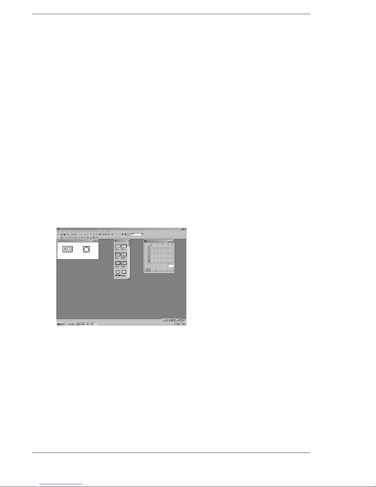
Screens can be created easily, using special tools
Screen contents can be easily created using the dedicated Terminal GTWIN tool (runs
on Windows 95/98/2000/NT/XP). Screens are put together simply by selecting parts
from a library and positioning them in place.
Page 19
An Overview of GT01 Functions
GT series
xvii
Ultra-thin body is only 24 mm/0.94 inch deep
The in-panel depth is a mere 24 mm/0.94 inch (including the fittings), configuring an
ultra-thin body and taking up a bare minimum of space.
Through function is convenient for debugging
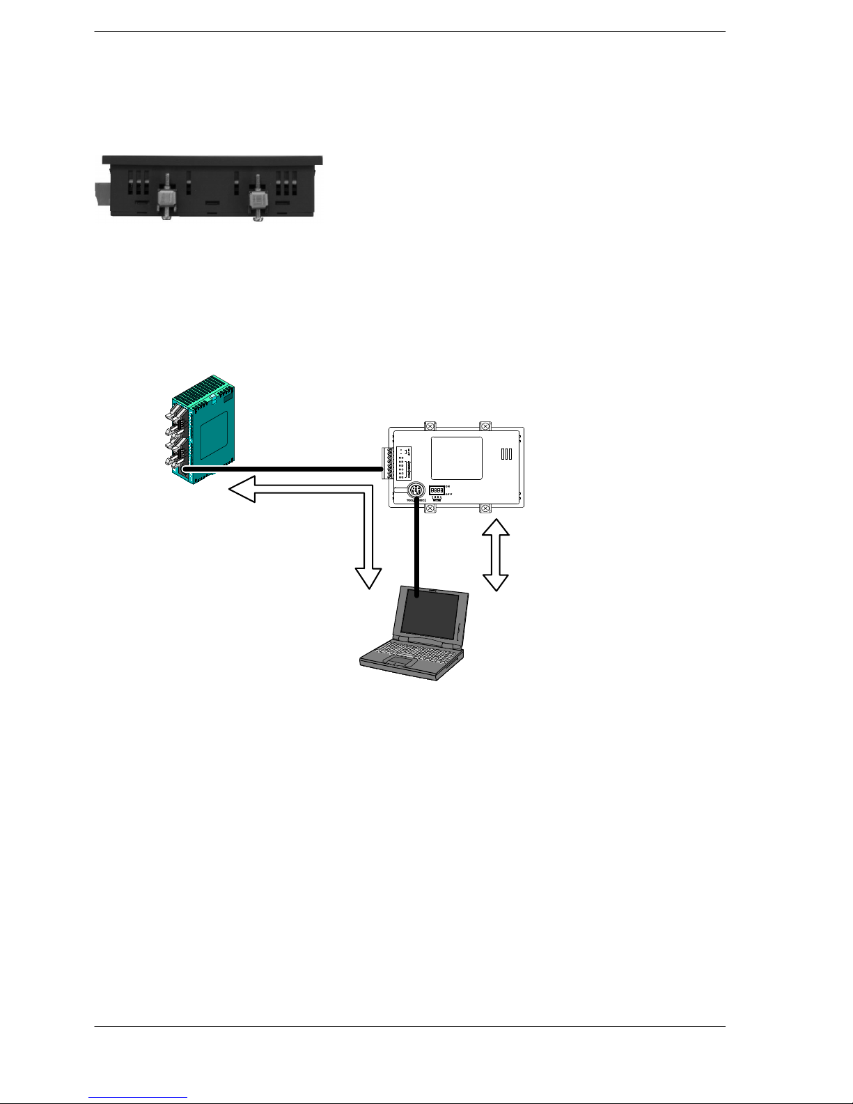
Ifconnectionsaremadeasshowninthe diagram,aconvenient“through” functionmakes
itpossible to transferdata from theGT01 and carryoutPLCdebugging atthesame time
that communication is going on between the GT01 and the FP series PLC. This
significantly boosts efficiency in the workplace.
PLC
GT01
Cable connected to
the TOOL port of the
PLC.
Screen
transfer
cable
AFC8503
PLC debugging
Screen data
being sent
and received
Screen creation tool GTWIN
FP series programming tool
FPWIN GR
Personal computer
The FPWIN GR can be booted on
the computer being used to edit GT
series screens, and PLC programs
edited and monitored through the
GT series.
Maintenance is easier than ever before
LEDsare usedfor thebacklight. Thiseliminates the need for troublesome replacement.
Also, screen data is saved to F-ROM and batteries are not used. (There is no clock
function.) You may safely use the GT01 for a very long time.
Page 20

GT seriesAn Overview of GT01 Functions
xviii
Page 21

Chapter 1
Specifications
Page 22

GT seriesSpecifications
2
Page 23
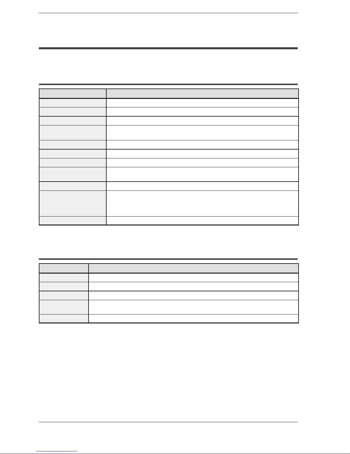
SpecificationsGTseries
3
1.1 GT01 Specifications
1.1 GT01 Specifications
1.1.1 General Specifications
Item GT01 specifications
Rated voltage 5VDC
Operating voltage range 4.5 to 5.5 V DC
Power consumption 1 W max.
Ambient temperature
0°Cto50°C/32°F to 122°F
(5 V DC max. if installed horizontally)
Ambient humidity 20% RH to 85% RH (non condensing)
Storage temperature
-20°Cto60°C/-4°F to 140°F
Storage humidity 10% RH to 85% RH (non condensing)
Vibration resistance
10Hz to 55 Hz (1-minute cycle)
Amplitude: 0.75 mm, 10 min on 3 axes
Shock resistance 98 m/s2min., 4 times on 3 axes
Protective construction
IP65 (in initial status)
Dustproof and drip-proof from front panel only (packing used on panel contact surface)
* When reattaching, replace waterproof packing.
Mass Approx. 160 g/5.644 oz
1.1.2 Display
I
tem
GT01
spec
ifi
cations
Display STN monochrome LCD
Resolution 128 (W) x 64 (H) dots
Display color 2 colors (black/white)
Displayable area
78.5 (W) x 37.1 (H) mm
3.09 (W) inch x 1.46 (H) inch
Backlight 3-color LED backlight (green, red, orange)
Page 24
GT seriesSpecifications
4
1.1 GT01 Specifications
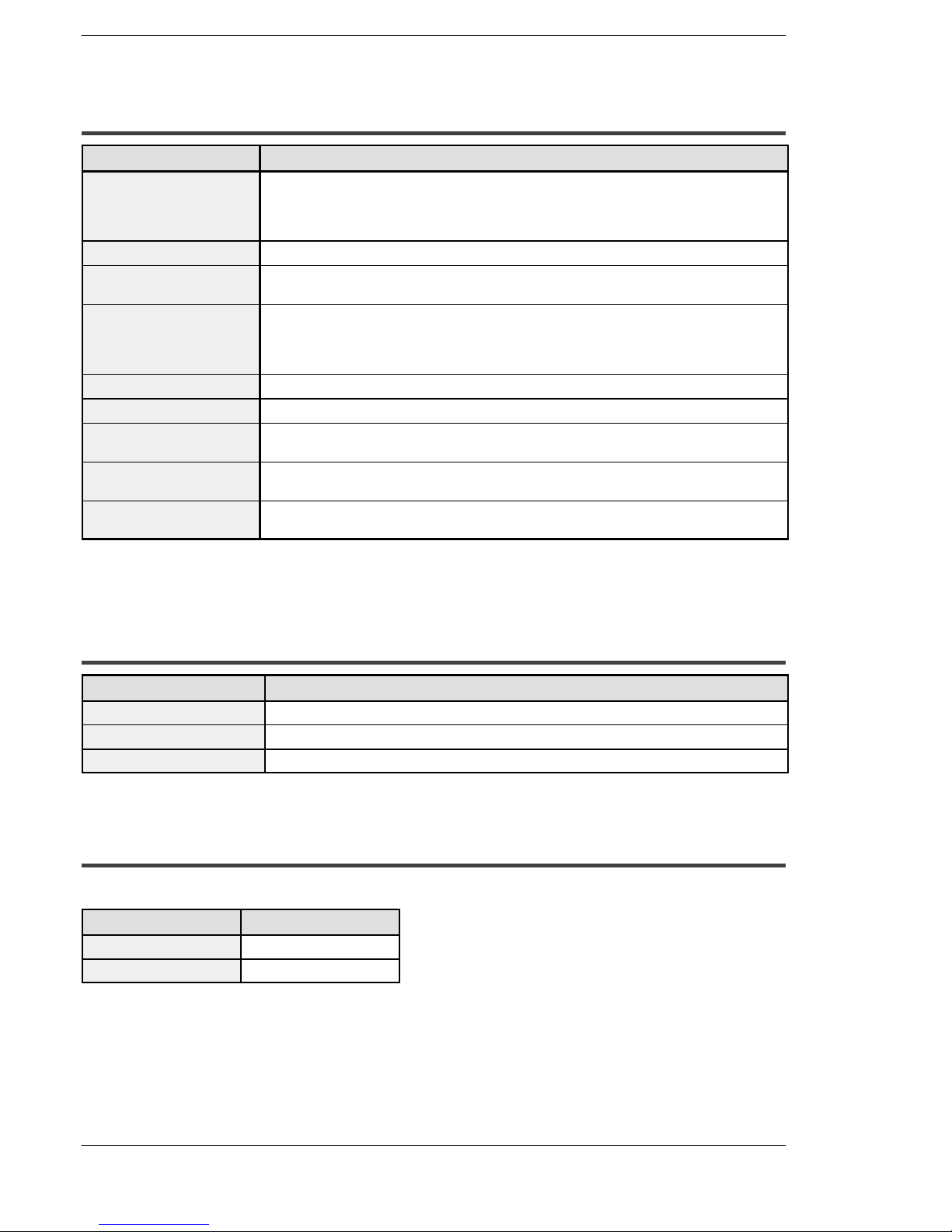
1.1.3 Functions
Item GT01 specifications
Displayable fonts
Fixed fonts: 1/4 width (8 x 8), half width (16 x 8), full width (16 x 16)
Half width and full width characters can be displayed at same width, doubled width, or
quadrupled width
True Type fonts
Character types Alphanumeric characters
Graphics
Straight lines, continuous straight lines, squares, circles, ovals, arcs, elliptic arcs, fan
shapes, elliptic fan shapes, beveled squares, bitmaps
Number of screens
Screen numbers that can be set: Base screens No. 00 to FF (HEX)
Number of screens that can be registered varies depending on registered contents.
No. of parts that can be registered for one screen: 256 (Note: this includes the number of message part replacements.)
Part functions Messages, lamps, switches, data, bar graphs, clocks, keyboard
Contrast
adjustment Contrast can be adjusted using touch panel operation
Automatic
communication settings
Settings for communication between dedicated software and PLC set automatically by
connecting cable
Debugging functions
Through function (PLC can be debugged from personal computer by connecting computer to TOOL port and PLC to COM. port)
Screen creation
Dedicated software Terminal GTWIN used.
Applicable OS: Windows 95/98/2000/NT/XP
* Clock functions are not available.
1.1.4 Touch Key
Item GT01 specifications
Touch key Analog touch key
Touch key operation 0.5 N max.
Touch key life Min. 10
6
1.1.5 Memory (1)
Screen data and GTWIN Configuration Settings data
I
tem
GT01
spec
ifi
cations
Memory type F-ROM
Memory capacity 384 kbytes
Page 25
SpecificationsGTseries
5
1.1 GT01 Specifications
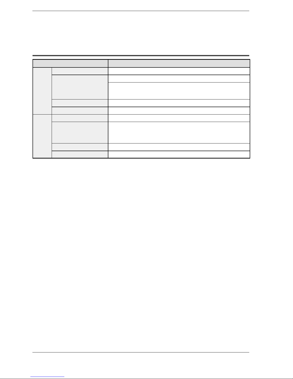
1.1.6 Interface
Item GT01 specifications
Communications ratings Conforms to RS232C
Baud rate: 9600, 19200, 38400, 57600, 115200 bits/s
COM.
Port
Conditi
onsfor
communications with
external devices
Data bits: 7 or 8 bits
Parity: None, Odd, Even
Stop bits: 1 bit
Protocol FP series supported/general-purpose RS232C supported
Connector Connector terminal base (8-pin)
Communications ratings Conforms to RS232C
TOOL
port
Conditions for
communications with
external devices
Baud rate: 9600, 19200, 115200 bits/s
Data bits: 8 bits
Parity: None, Odd, Even
Stop bits: 1 bit
Protocol Dedicated protocol
Connector
Mini-DIN (5-pin)
Page 26
GT seriesSpecifications
6
1.2 GT01 Names and Functions of Parts
1.2 GT01 Names and Functions of Parts
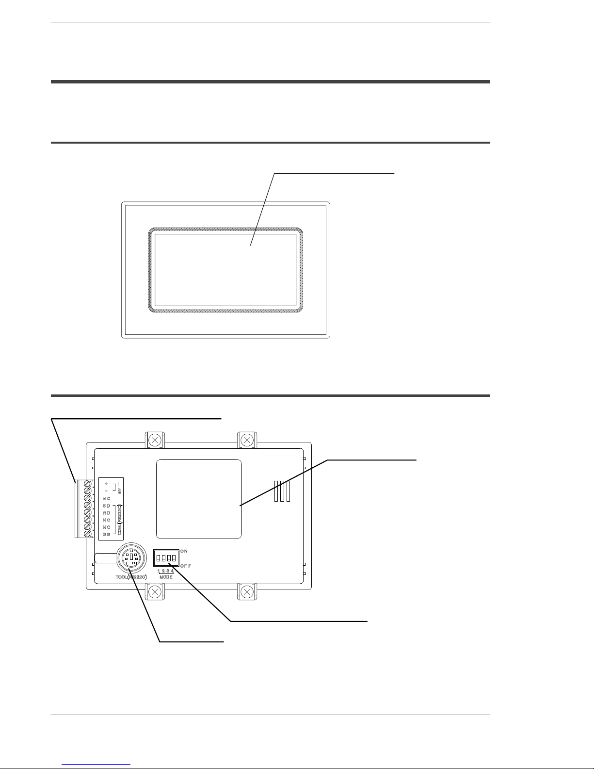
1.2.1 GT01 (front)
F
Liquid crystal display panel
(touch panel)
1
1.2.2 GT01 (rear)
F
COM. port and power supply terminal
2
F
Waterproof packing
5
F
TOOL port
3
F
4
Operation mode setting switches
Page 27
SpecificationsGTseries
7
1.2 GT01 Names and Functions of Parts
1.2.3 Names and Functions of Parts
(1) Liquid crystal display panel / touch panel
Various screens are displayed here. A touch panel is provided on the liquid crystal
display panel, and switches can be operated and data entered simply by touching the
panel.
Optionalprotectivesheetsarealsoavailableto protectthetouchpanel and keepitclean.
(A sheet is affixed to the touch panel to protect it from scratches when shipping. Please
remove it before using the GT01.)
(2) COM. port (PLC/external device connection port) and power supply terminal
This is an RS232C port for connectingto a PLC, hostPC, or microcomputer board, and
a 5 V DC operation power supply terminal. (The GT01 is shipped with one
communications connector.)
(3) TOOL port (GTWIN connection port)
This port is used to connect a personal computer in which the screen creation tool
GTWIN has been installed, using a dedicated cable (AFC8503).
(4) Operation mode setting switches
With the GT01, screen data and configuration settings data are stored in an internal
F-ROM, so no battery backup is needed.
The operation mode setting switch has a switch that prohibits access to the System
Menu.
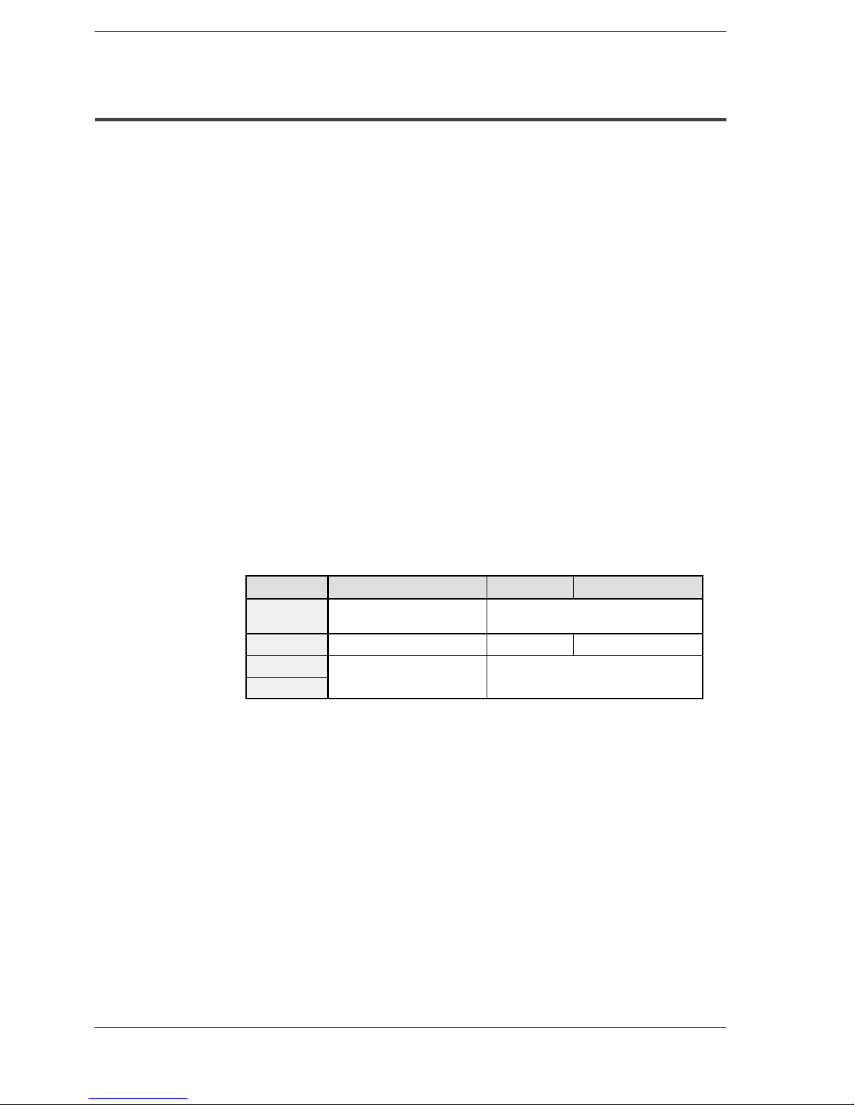
Switch no. Function OFF ON
1
Usage inhibited Should always be in the OFF position
when unit is used
2 Inhibits system menu shift Shift possible Shift inhibited
3 Usage inhibited Should always be in the OFF position
4
when unit is used
(5) Waterproof packing
This assures that the front panel is waterproof. One piece is provided as an accessory
when the unit is shipped.
Operation mode setting
switches
(settings when shipped)
Page 28
GT seriesSpecifications
8
1.3 Internal Wiring Connections for Ports
1.3 Internal Wiring Connections for Ports
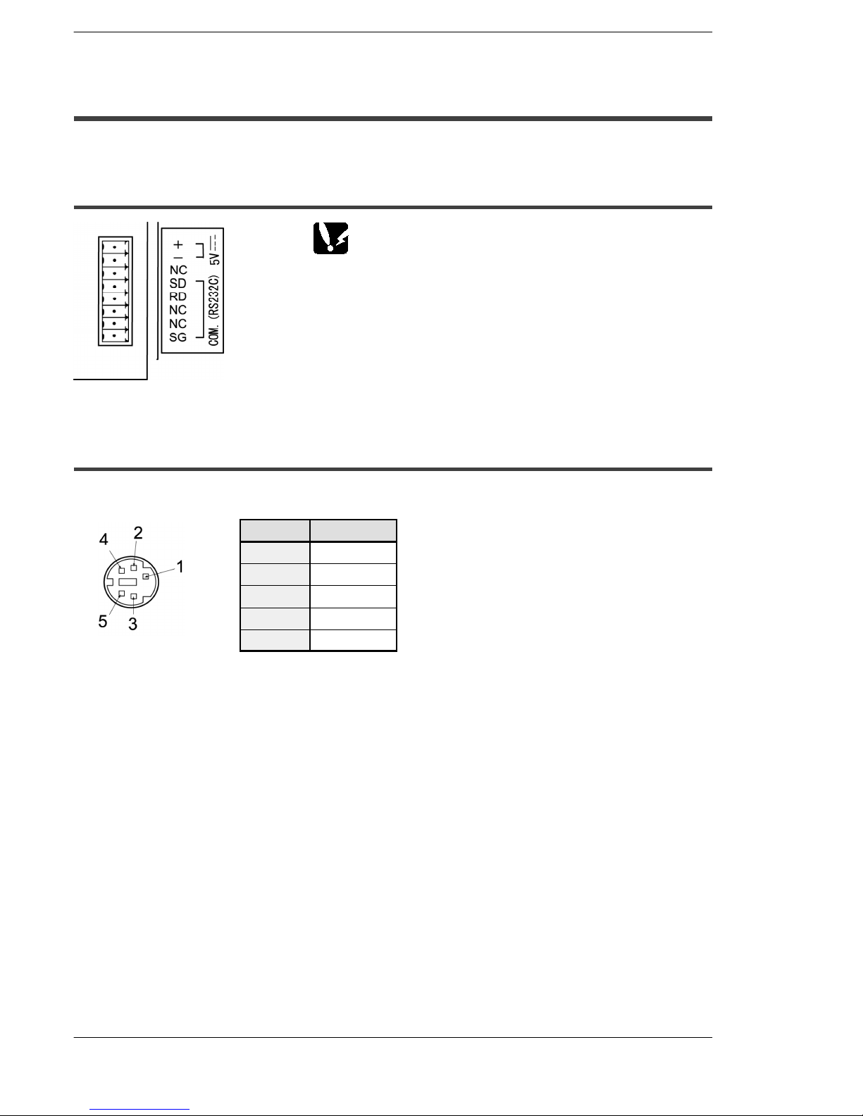
1.3.1 COM. Port
Wiring and cables should be laid out in such a way
that cables are not affected by external noise. Also,
shielded wiring should be used for cables.
1.3.2 TOOL Port
Pin No. Contents
1 SG
2 SD
3 RD
4 N.C.
5 N.C.
Page 29
SpecificationsGTseries
9
1.4 Dimensions
1.4 Dimensions
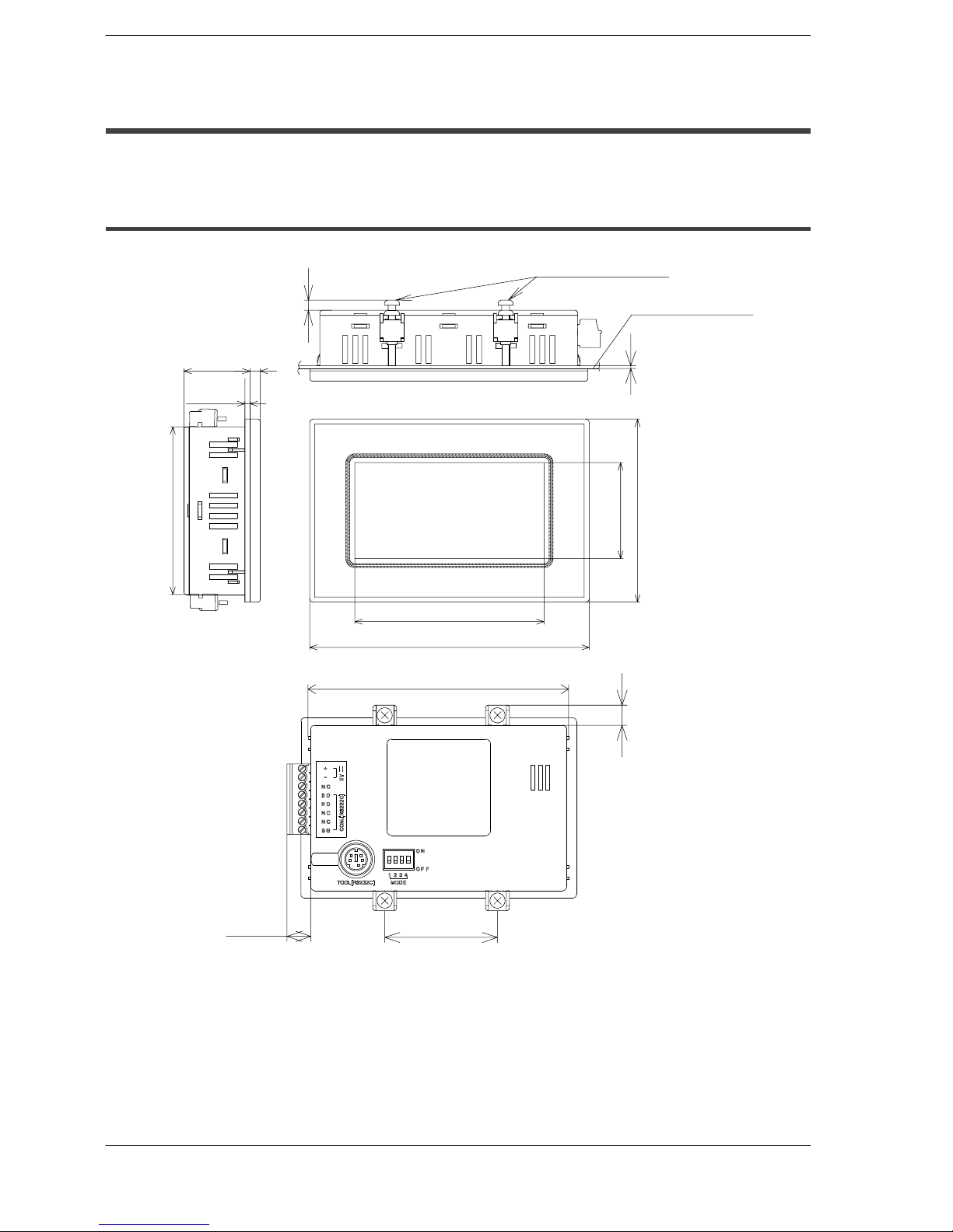
1.4.1 GT01 Dimensions
45 / 1.77
110 / 4.33
72 / 2.83
4/
0.16
4 / 0.16
1 / 0.04
37.7 / 1.48
(Display unit)
74.5 / 2.93 (Display unit)
2 / 0.08
(Packing)
66 / 2.60
24 / 0.94
104 / 4.09
9.5 / 0.37
Panel thickness
5 mm 0.20 inch
Mounting panel
8 / 0.31
Page 30

GT seriesSpecifications
10
1.4 Dimensions
1.4.2 GT01 Panel Cutout Dimensions
The panel cutout dimensions of the GT01 are as shown below.
Applicable panel thickness:
1.0mm to 5.0mm
0.04inch to 0.20inch
105.00/ 4.13
+0.04
/ 2.64
+0.04
67.0
+
1
+1
0
*During installation when there will be other parts installed to the panel and wiring
performed, we recommend that you provide a 30 to 50 mm clearance around the GT01
as a precaution against potential cable damage and to improve work efficiency when
performing the installation.
Caution 1: Be absolutely sure not to seal the slits on the GT01.
Page 31

Chapter 2
Installation and Wiring
Page 32

GT seriesInstallation and Wiring
12
Page 33

Installation and WiringGT series
13
2.1 Installation
2.1 Installation
2.1.1 Installation Environment
When installing and usingthe GT series, always make sure the following conditions are
observed.
Usage Conditions
When installing the product, make sure it is used within the range of the general
specifications. Do not use in the following environments:
- Areas where the unit may come in contact with water (the unit is warranted by
IP65 for the installed panel, but this applies to initial values and operation cannot
be guaranteed in areas where the unit is constantly subjected to water or to
extreme temperatures or humidity).
- Areas where the ambient temperature exceeds the range 0°Cto50°C/32°Fto
122°F.
- Areas where the ambient humidity exceeds 20% RH to 85% RH.
- If the control panel and other parts are installed in an environment where the air
tends to be poorly ventilated, forced cooling should be used to keep the ambient
temperature of the from going over 50°C/122°F. This prevents the temperature of
the GT display unit from rising.
- Locations where condensation may form because of sudden fluctuations in
temperature.
- Locations where flammable or corrosive gases are present.
- Locations where there are high concentrations of dust or iron filings.
- Locations where substances such as organic solvents (thinner, benzene, etc.) or
strong alkali substances (ammonia, caustic soda, etc.) might adhere to the
product.
- Locations where the product is subject to extreme vibration and/or impact.
- Avoid installing the product near high-voltage lines, high-voltage devices, power
lines, power devices, amateur radio sets and other transmitters, and devices that
generate strong current surges.
- Avoid locations where the display unit is subject to direct sunlight.
Safety Precautions
- The switch functions of the programmable display unit should not be used to
design systems which may pose a threat to human life or which may cause
severe injury or damage. Designs should include safety mechanisms for use in
the event that switch functions do not function correctly.
Page 34

GT series
Installation and Wiring
14
2.1 Installation
Power Supply Wiring
- For the power supply, use twisted wire (strand wire).
- There is sufficient noise resistance to offset power line noise, but we recommend
reducing noise by measures such as installing an insulated transformer.
- Separate wiring systems should be used for the power supply unit and the
operating unit.
Static Electricity/Noise
- Keep the GT01 main unit, PLC connecting cable, and other wiring as far away as
possible from machines which are likely to produce noise (welding equipment,
power lines, inverters, motors, etc.).
- For use in environments where the frequent occurrence of static electricity,
radiation, or induced noise can be expected, the use of shielded cable on all
wiring and grounding of shield (1-point ground) is recommended. When wiring
the equipment, shielded wires should be electrically insulated to signal lines and
signal grounds.
- If excessive static electricity is applied to the panel surface, the LCD display unit
may be damaged.
Other Precautions
- Do not leave the GT connected to the TOOL port of the FP Programmer II.
- Always operate the touch panel with your fingers. Excessive load (about 98
N/cm
2
) or impact (operating with tools, etc.) will cause damage. Touch panel
operation must be within the standard operating power range. Uniform pressure
should be used to avoid abnormal wear of electrodes which may disable
operation. Operate the unit only by touch.
- Never dismantle, re-assemble, or alter the unit. Performance cannot be
warranted if this precaution is disregarded.
Page 35
Installation and Wiring
GT series
15
2.1 Installation
2.1.2 GT01 Installation Method
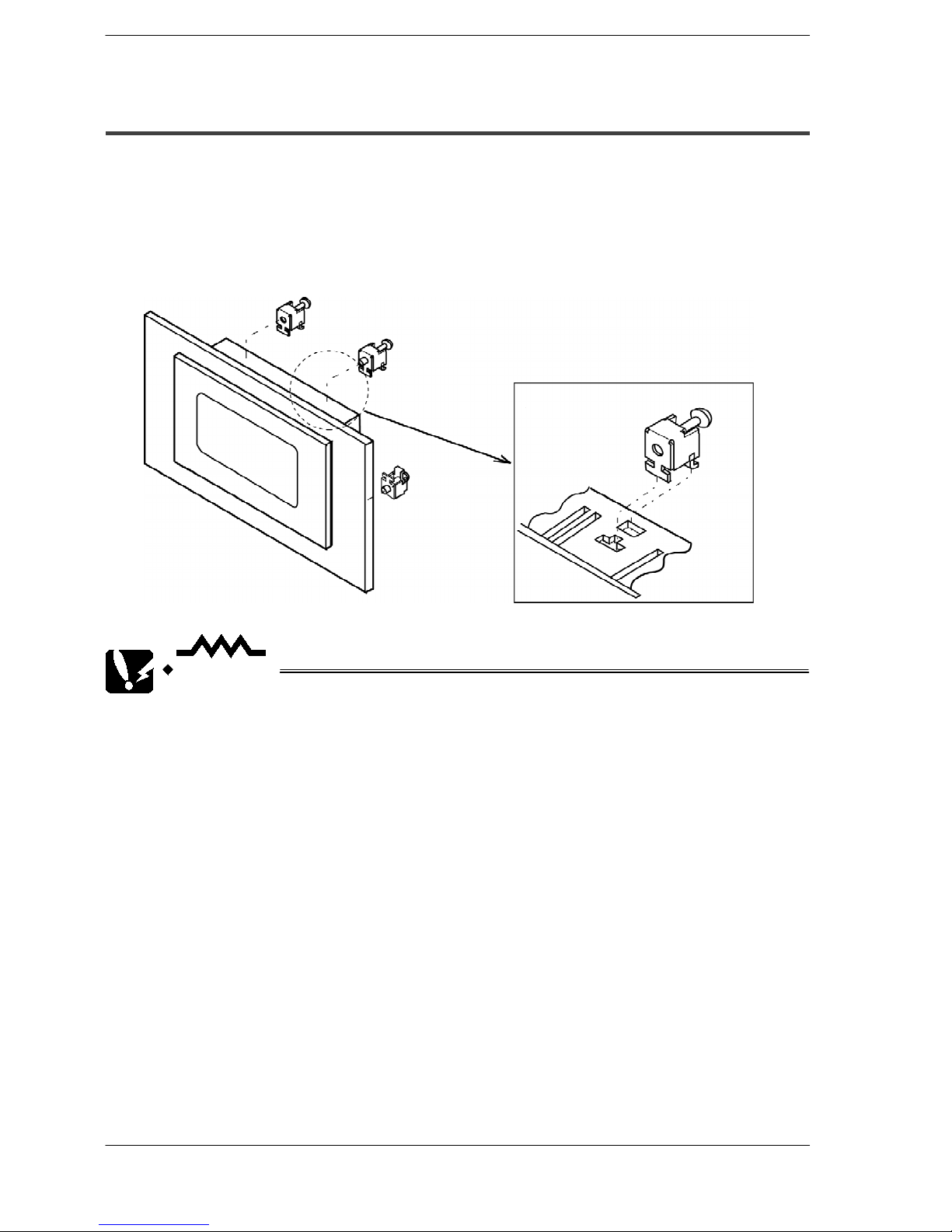
Secure the GT01 to the installation panel using the four fittings and four screws
provided with the unit.
(1) Place the GT01 main unit in the installation panel.
(2) Insert the fittings into the grooves provided in the GT01 main unit, and tighten
the screws to secure the GT01 main unit to the installation panel.
Enlarged view
CAUTION
•
Screw tightening torque
The screw tightening torque should be 0.1 N m to 0.25 N m.
•
Applicable panel thickness
A panel with a thickness of 1.0 mm to 5.0 mm should be used.
•
Clearance when the GT01 is installed
When installing the GT01, if other parts are being installed to the
panel or cables are being wired to it, we recommend providing a
clearance of 30 mm to 50 mm/1.18 inch to 1.97 inch around the GT01.
This prevents cables from being damaged, and facilitates the
installation work. Also, make sure that the slits in the main unit are
never obstructed.
Page 36
GT series
Installation and Wiring
16
2.2 Wiring the Power Supply
2.2 Wiring the Power Supply
2.2.1 Wiring the Power Supply
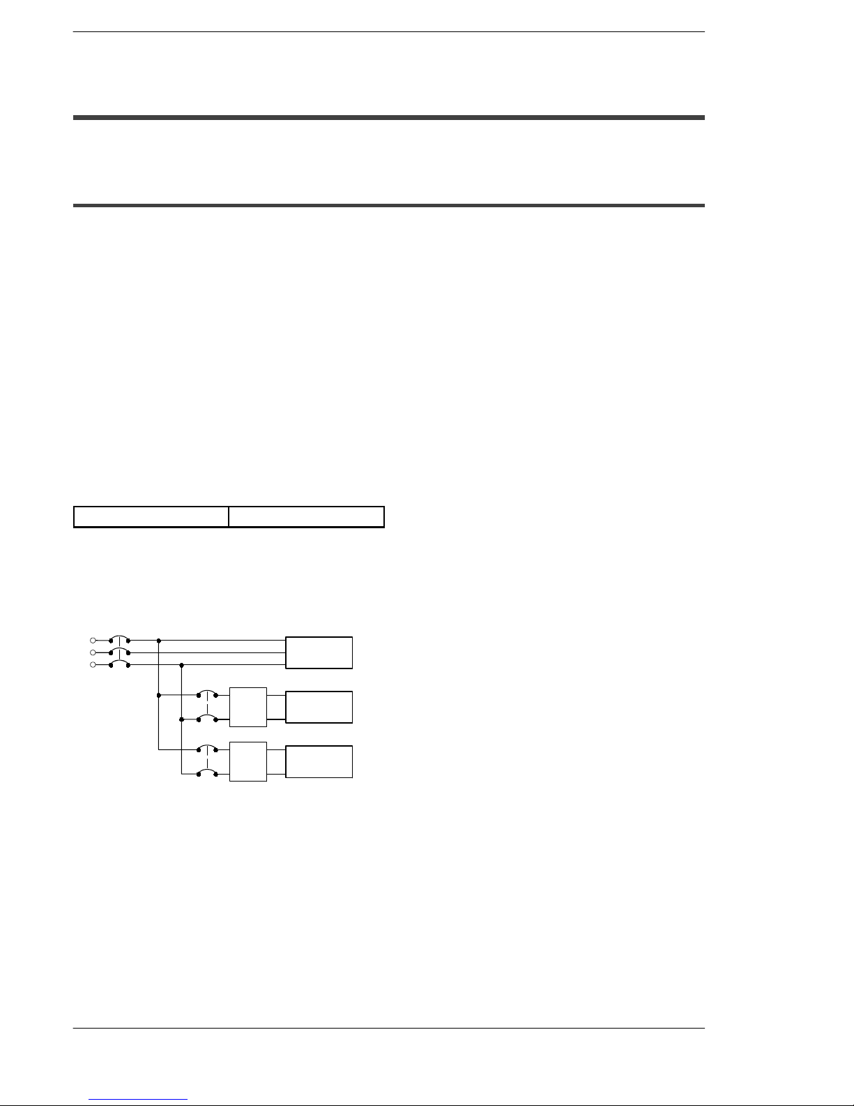
The power supply should be wired by securely connecting the terminal on the rear of
the main unit to the terminal.
Use twisted wiring for the power supply
In order to minimize influence from noise, the wiring for the power supply should be
twisted.
Insulate the power supply inside a protective circuit
- In order to protect the unit against abnormal voltage from the power supply line, the
power supply should be an insulated type, and should be enclosed within a protective
circuit.
- A non-insulated regulator is used with the GT series.
- If a power supply device without an internal protective circuit is being used, power
shouldalways be suppliedto theGT series through a fuseor asimilar protectivedevice.
Keep the power supply voltage within the operating voltage range
Operating voltage range 4.5 to 5.5V DC
Keep the power supply wiring separate
- Wiringtothe GT series,PLC,and other powerequipmentshouldhave separate wiring
systems.
PLC
GT series
Breaker
Power
equipment
Insulated DC
power supply
Page 37
Installation and Wiring
GT series
17
2.3 Wiring the COM. Port
2.3 Wiring the COM. Port
2.3.1 Wiring the COM. Port
Accessory communication connector/applicable wiring
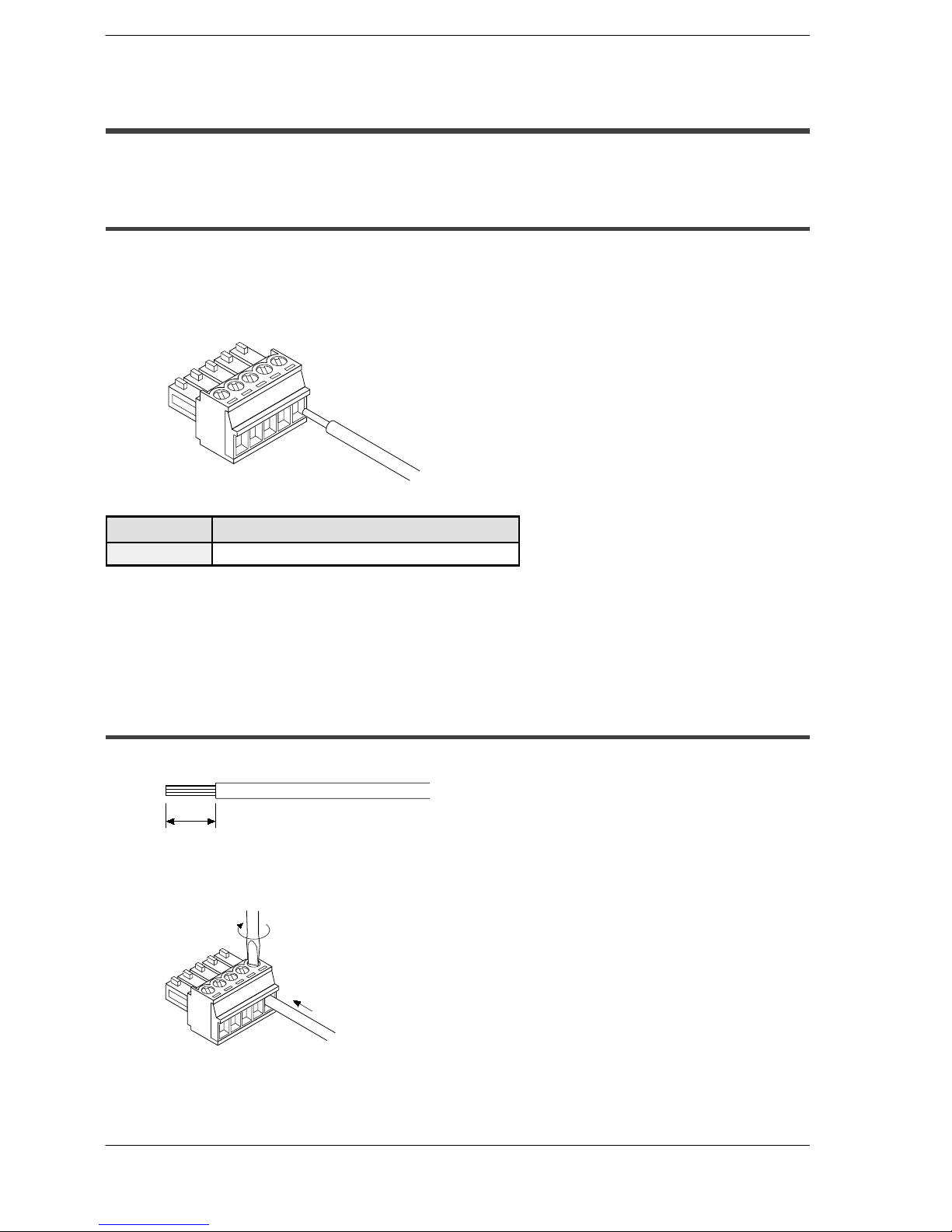
The communication connector used for the COM. port (provided as an accessory with
the main unit) has a screw-tightening type of terminal base. The wiring shown below
should be used.
Applicable wiring (twisted wiring)
Size Conductor Cross-Section Surface Area
AGW#28 to 16
0.08 mm2to 1.25 mm
2
Use a special tool to tighten the terminal base of the communication connector
Using a screwdriver made by Matsushita Electric Works Co., Ltd. (Product number
AFP0806). The tightening torque should be 0.22 N·m to 0.25 N·m or less.
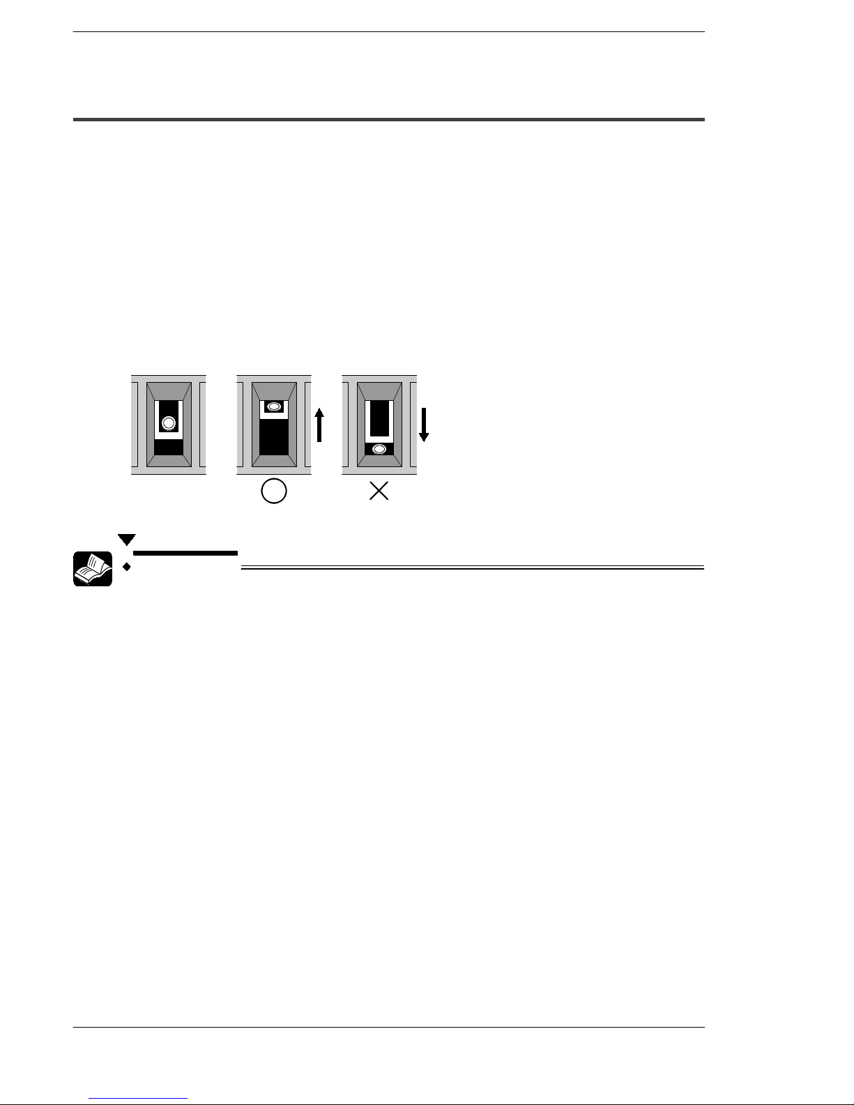
2.3.2 Wiring Method
(1) Remove the sheath from the wire.
7 mm/0.28 inch
(2) Insert the wire all the way into the terminal base, and tighten the screw in the
clockwise direction to secure it.
Page 38
GT series
Installation and Wiring
18
2.3 Wiring the COM. Port
2.3.3 Precautions Concerning Wiring
The following precautions should be observed, to avoid broken or disconnected wires.
- When removing the sheath, be careful not to scratch the core wire.
- Wire the terminal without twisting the core wire.
- The core wire should be connected without soldering it. Vibration can sometimes
cause soldered connections to break loose.
- After connecting the wiring, avoid subjecting the cable to stress.
- Because of the construction of the terminal, tightening the wire in the
counterclockwise direction will cause a faulty connection. If this happens,
disconnect the wire, check the terminal hole, and connect the wire again.
CounterclockwiseClockwise
REFERENCE
For information on connecting the COM. port of the GT series with
various PLC units, please see Chapter 4, “Connecting and
Communicating with the PLC”, on page 27.
Page 39

Chapter 3
Setup
Page 40

GT seriesSetup
20
Page 41
SetupGTseries
21
3.1 Setup Procedure for the GT01
3.1 Setup Procedure for the GT01
3.1.1 Setup Procedure
The GT01 should be set up using the procedure outlined below.
(1) Setting the “Configuration File” with GTWIN
The GT01 has an internal file called the “Configuration file”, which is used to determine
variousoperatingenvironment parameters. Whenthe GT01is shipped from the factory,
the settings listed below are set for the parameters in the configuration settings file. If
changes are made to these settings, they are made from GTWIN screen creation tool.
If the GT01 is being used without changing the factory settings, the following setup
procedure is not necessary.
Contents of configuration settings for GT01 when shipped from the factory
Classification Item Setting contents
Basic Setup
Area for basic
communication
with PLC
Mode : GT01 mode
Word area: DT0 to DT2
Bit area : WR0 to WR2
Communication
parameter
COM. port
Communication speed: 19200 bits/s, datalength: 8 bits, stop bit: 1 bit, parity: odd
<Communication error temporary processing> Retries: 3, error code displayed
(not held)
parameter
settings
TOOL port
Communication speed: 19200 bits/s, datalength: 8 bits, stop bit: 1 bit, parity: odd
<Through function local setting> None
Auto paging
Automatic paging No
Startup screen
Startup screen No. 00
Startup
screen
settings
Rise delay time 0 seconds
Backlight control Not turned off automatically
Other settings
Touch operation
sounds
Valid
Always confirm “Basic communication area to PLC” under “Basic Setup”
Thisis an internal device area that comes already provided in the GT01 for thepurpose
of communicating with a PLC. If the factory settings are to be changed, the setup
procedure must be carried out. For detailed information, please see page 24.
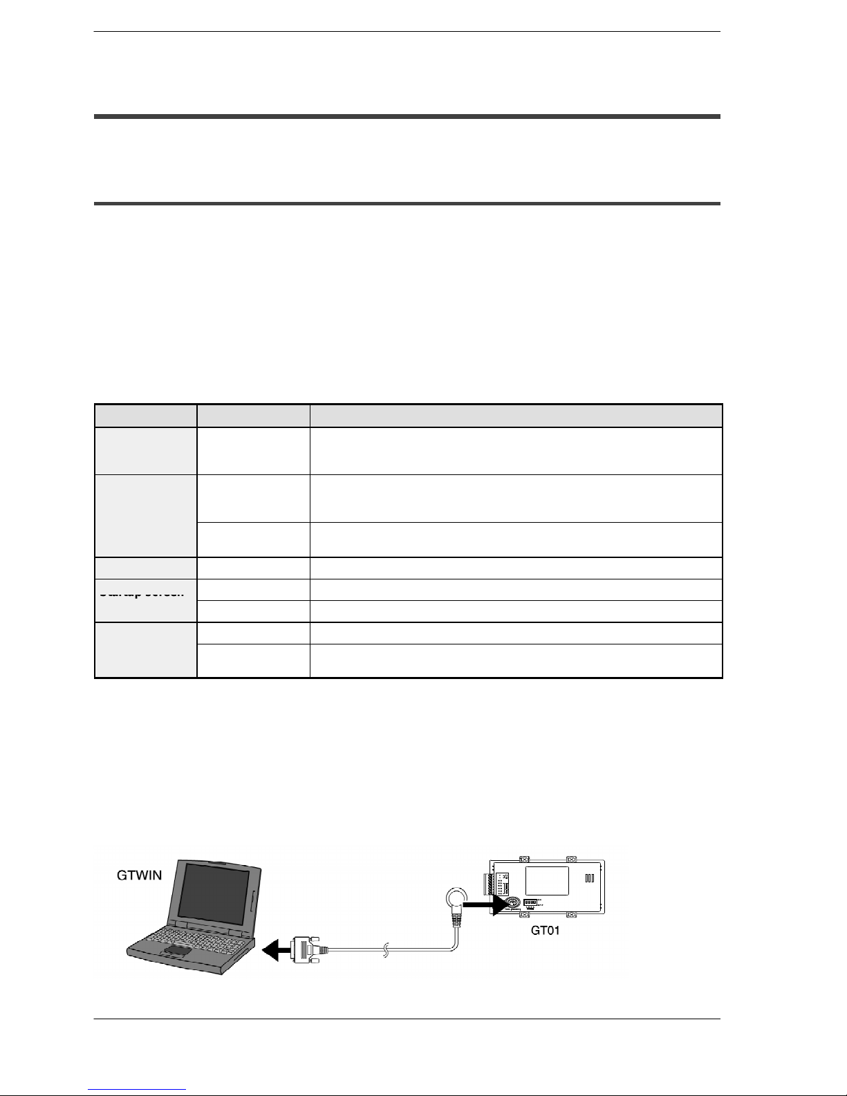
(2) Connect the GT01 and the personal computer.
After the settings have beenentered withGTWIN, connect the computer and the GT01,
using the screen transfer cable.
Screen transfer
cable (AFC8503)
Page 42
GT series
Setup
22
3.1 Setup Procedure for the GT01
(3) Transfer the GT01 Configuration file from GTWIN.
After connections have been completed, use the following procedure to transfer the
GT01 Configuration file from GTWIN.
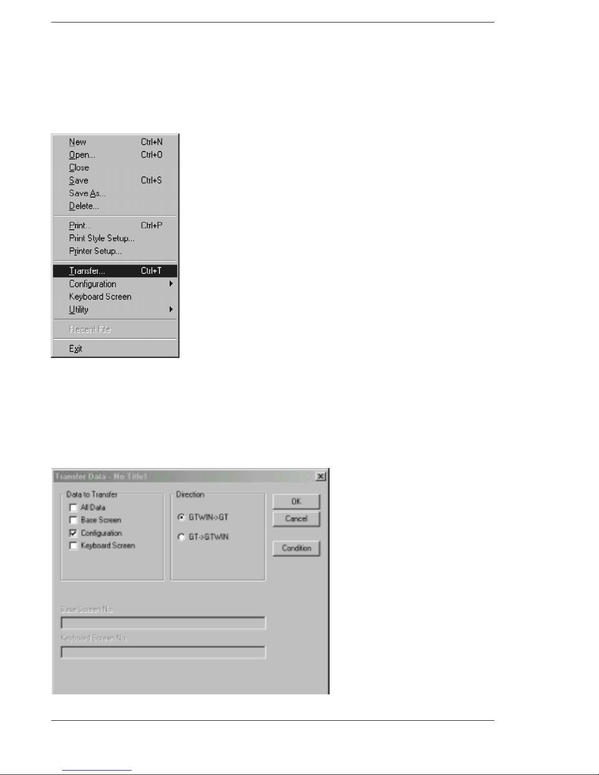
Boot GTWIN, and select “Transfer” on the “File” menu.
When the transfer function is selected, a dialog box for file transfer is displayed.
At this point, specify the type of data to be transferred, and the direction of
transfer.
Transfer data: “GT01 Configuration”
Transfer direction: “GTWIN→GT main unit”
Enter the above conditions and click on the “OK” button. The system files are
transferred to the GT01.
Page 43
Setup
GT series
23
3.1 Setup Procedure for the GT01
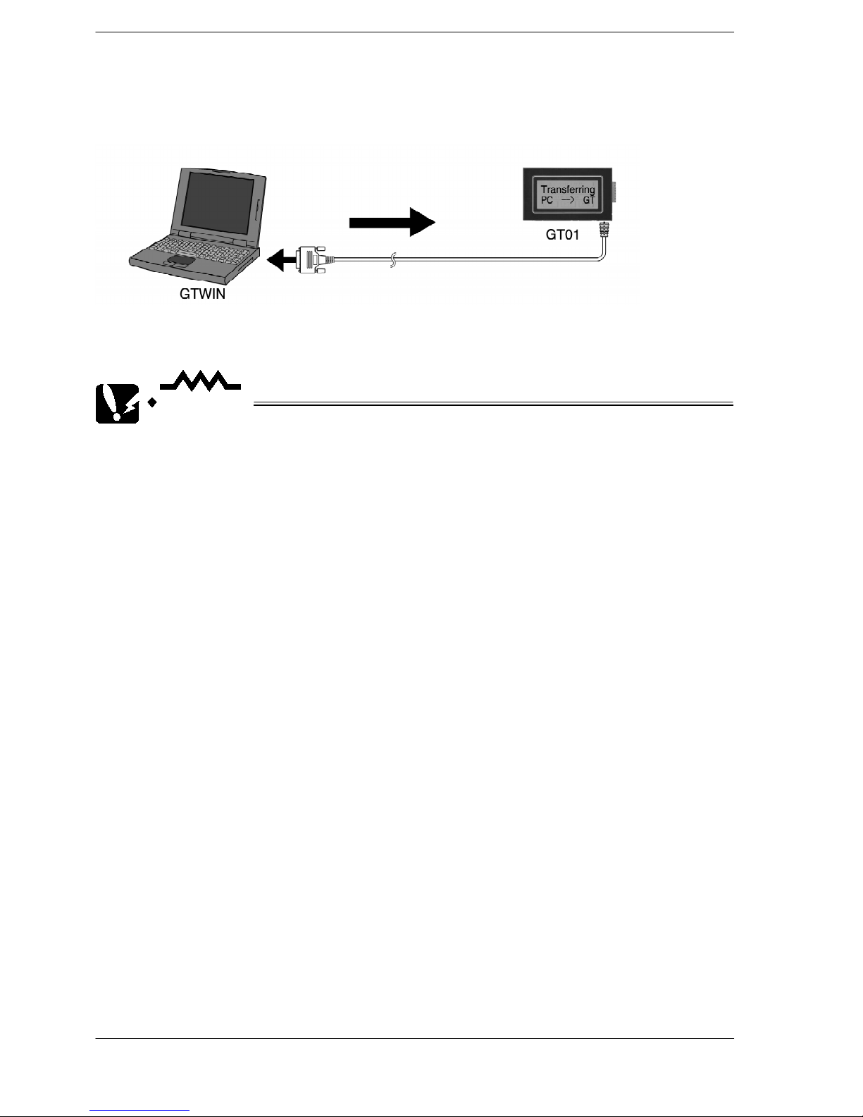
When the menu operation as shown at the left page is carried out, the configuration file
is sent to the GT01. During the transfer, a screen like that shown below is displayed.
Screen transfer cable
(AFC8503)
GT01 Configuration
file being transferred
(4) Setup is completed.
If the transfer has been completed without any problems, the setup is completed.
CAUTION
Backup of the GT01 Configuration file
The GT01 Configuration file is stored in the user memory (F-ROM) of the
GT01. This file is deleted if the memory is initialized using the command
on the system menu of the GT01 main unit (see page 56), and will have
to be transferred again.
Page 44
GT series
Setup
24
3.2 Setting the Basic Communication Area Between the GT01 and PLC
3.2 Setting the Basic Communication Area Between the
GT01 and PLC
3.2.1 What is the Basic Communication Area?
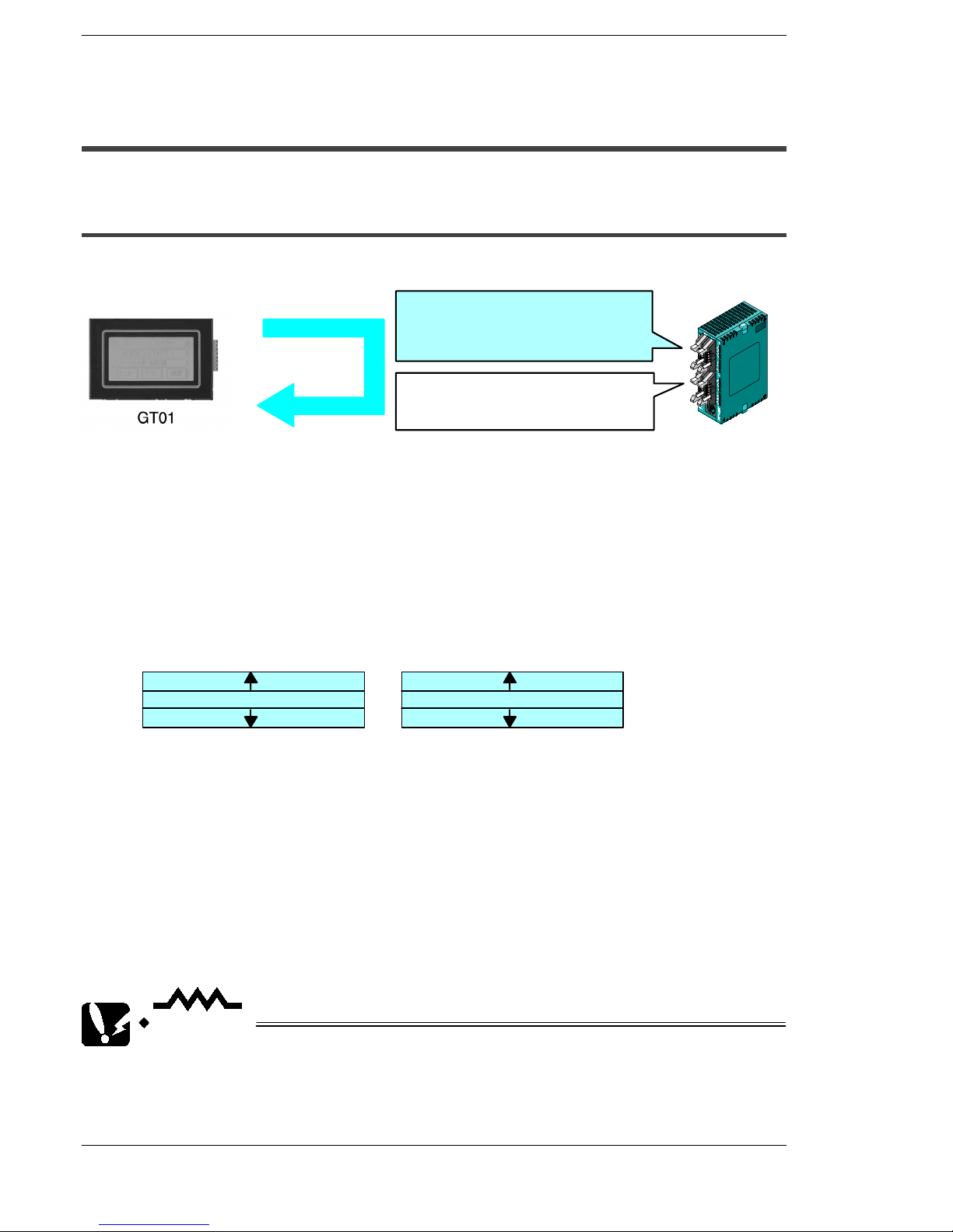
Communication between the GT01 and PLC is carried out as shown below.
PLC
Internal PLC devices
Partreference /output device
For part functions
(free device specification)
Basic communication area
For screen switching settings and system
control
(word device / bit device: 3 words each)
Ongoing
Communication
As shown in the illustration, communication is carried out on an ongoing basis between
the GT01 and internal devices in the PLC. Internal PLC devices are divided into the
following two devices:
Basic communication area
This area is for system control, such as screen switching settings. PLC devices belong
to this area on a fixed basis, and communication is constantly being carried out.
Breakdown of the basic communication area
Word devices (DT, FL, etc.)
3 consecutive words
Bit devices (WR, etc.)
3 consecutive words
- Word devices -- - For reading devices handled in word units (3 consecutive words)
- Bit devices -- - For reading devices handled in bit units (3 consecutive words)
References and output devices for parts
These are devices that are used in parts functions, and can be freely specified by the
user.Communication is carried out on anongoing basis only for those that are currently
displayed on the screen and pertain to devices currently in use.
With the GT01, before GTWIN screen creation tool is used to specify the devices for
parts functions, the “basic communication area” must be determined.
DT0to DT2 andWR0 to WR2 are set as the default values for the basiccommunication
area, but the initial address can be changed using the following procedure.
CAUTION
The basic communication area should be used in the PLC ladder
program to control the GT main unit.
Page 45
Setup
GT series
25
3.2 Setting the Basic Communication Area Between the GT01 and PLC
Settings in GTWIN
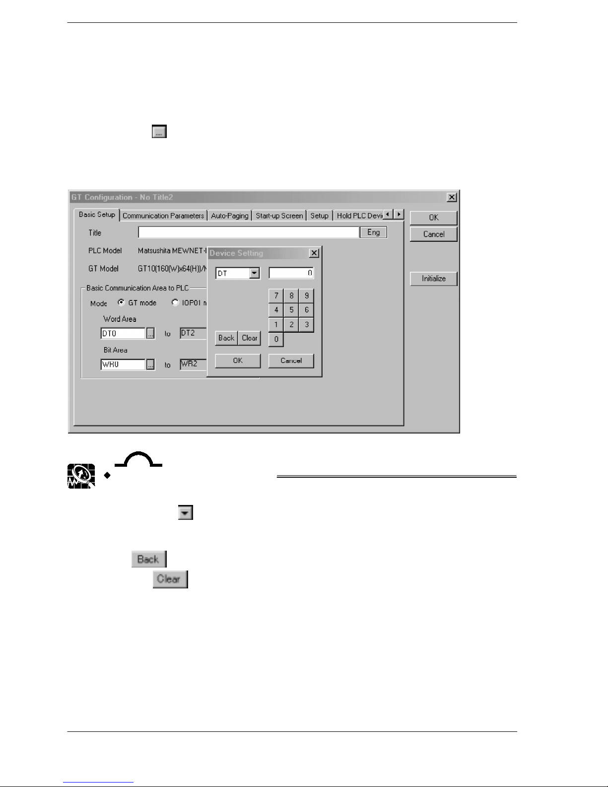
Select “Configuration” under “File” on the menu bar, and then select the sub-menu
called “GTWIN Configuration”. This displays the dialog box for the GT01 Basic Setup,
as shown below.
Clicking on the
button in “Basic Communication Area to PLC” displays the device
settings dialog box shown below, where the initial addresses for the word area and bit
area can be changed.
GT01 Configuration Basic Setup dialog box
Explanation of this function
Key operation in the Device Settings dialog box
Click on the
button to display a pull-down menu, and then select
the device for which settings are to be entered. Use the ten-keys to
enter the address.
The
button acts as a backspace key when entering an address,
and the
button functions as a Clear key.
Page 46
GT series
Setup
26
3.2 Setting the Basic Communication Area Between the GT01 and PLC
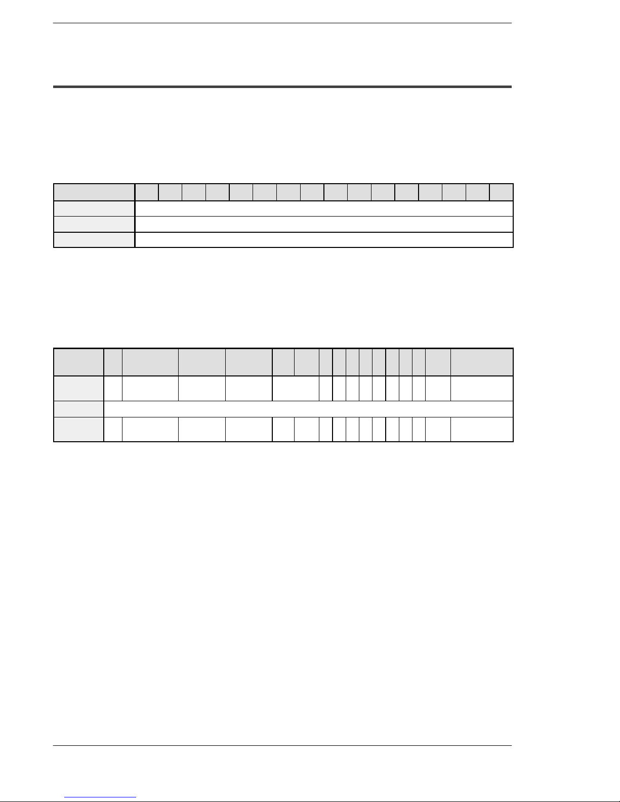
3.2.2 GT01 Basic Communication Area Map
In order for communication to be carried out between the GT01 and PLC, an internal
devicearea likethat shownbelow is provided in the PLC. This should be used tocontrol
the GT main unit through the PLC ladder program actually being run.
The starting address “N” of the field shownbelow is specified in the GT01 configuration
settings of GTWIN screen creation tool, and is then sent to the GT main unit.
Word devices
Word position F E D C B A 9 8 7 6 5 4 3 2 1 0
N+0
Screen no. specified by PLC (area read by GT01 from PLC)
N+1
Usage prohibited
N+2
No. of currently displayed screen (area in which data is written from GT01 to PLC)
Explanation of system area
Screen no. specified by PLC - - - The screen number displayed on the GT01 is
specified from the PLC in hexadecimal format.
No. of currently displayed screen - - - The number of the screen currently
displayed on the GT01 is written to the PLC in hexadecimal format.
Bit devices
Word
position
F E D C B A 9 8 7 6 5 4 3 2 1 0
N+0
BZ
Forceddisplay flag
Backlight
Validflag
Backlight
Flashing
Backlight
Color
N+1
Usage prohibited
N+2
Data Input In
Progress flag
Explanation of system areas
BZ -- - This turns on the buzzer.
Forced-Display flag
- - - At the rise when the bit is turned on, the screen specified by
the PLC is forcibly displayed. (This is executed only when at the rise of the bit.)
Backlight Valid flag
- - - When the bit is turned on, the backlight flashing/backlight
color control becomes effective.
Backlight Flashing
- - - 0: Lighted (normal), 1: Flashing
Backlight Color
- - - 00: Off, 01: Green, 10: Red, 11: Orange
Data Input In Progress flag
- - - This is 1 while data is being input, and 0 when data
input has been completed.
Page 47

Chapter 4
Connecting and Communicating with the
PLC
Page 48

GT seriesConnecting and Communicating with the PLC
28
Page 49
Connecting and Communicating with the PLCGT series
29
4.1 Connecting the FP
Σ
4.1 Connecting the FPΣ
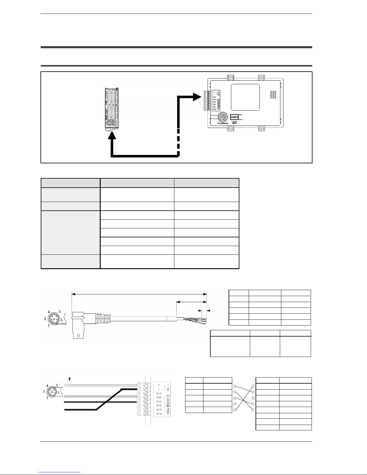
4.1.1 Connecting to the TOOL Port
AIGT8142
FPΣ TOOL port
FPΣ communication format settings
System register no. Item Value Set
410
TOOL Port
Unit number
1
412
Modem connection No modem connection
413
Data length 8 bits
Parity check Yes, Odd
Stop bits 1 bit
Line return code CR (Fixed)
Start code no STX (Fixed)
415
COM. Port 1
Communication speed setting
19200 bits/s
PLC communication cable: Mini-DIN 5-pin loose-wire cable (AIGT8142)
7/0.28
30/1.18
2000/78.74
Mini-DIN plug side signals
1 SG Brown
2 SD Red
3 RD Orange
4-- -5 +5V White
Pin no. Abbreviation Wire color
Specifications L Product No.
2 m/6.56 ft
Mini-DIN 5-pin
Single-side
4 loose wires
AIGT8142
Connecting to the FPΣ TOOL port
GT01
No. 1 (brown)
Pin no. on PLC side
No. 3 (orange)
No. 2 (red)
PLC side
Pin no.
Abbreviation
1SG
2SD
3RD
4-5 +5V
Abbreviation
GT main unit side
Pin no.
1+
23NC
4SD
5RD
6NC
7NC
8SG
No. 5 (White)
Page 50
GT series
Connecting and Communicating with the PLC
30
4.2 Connecting the FP0
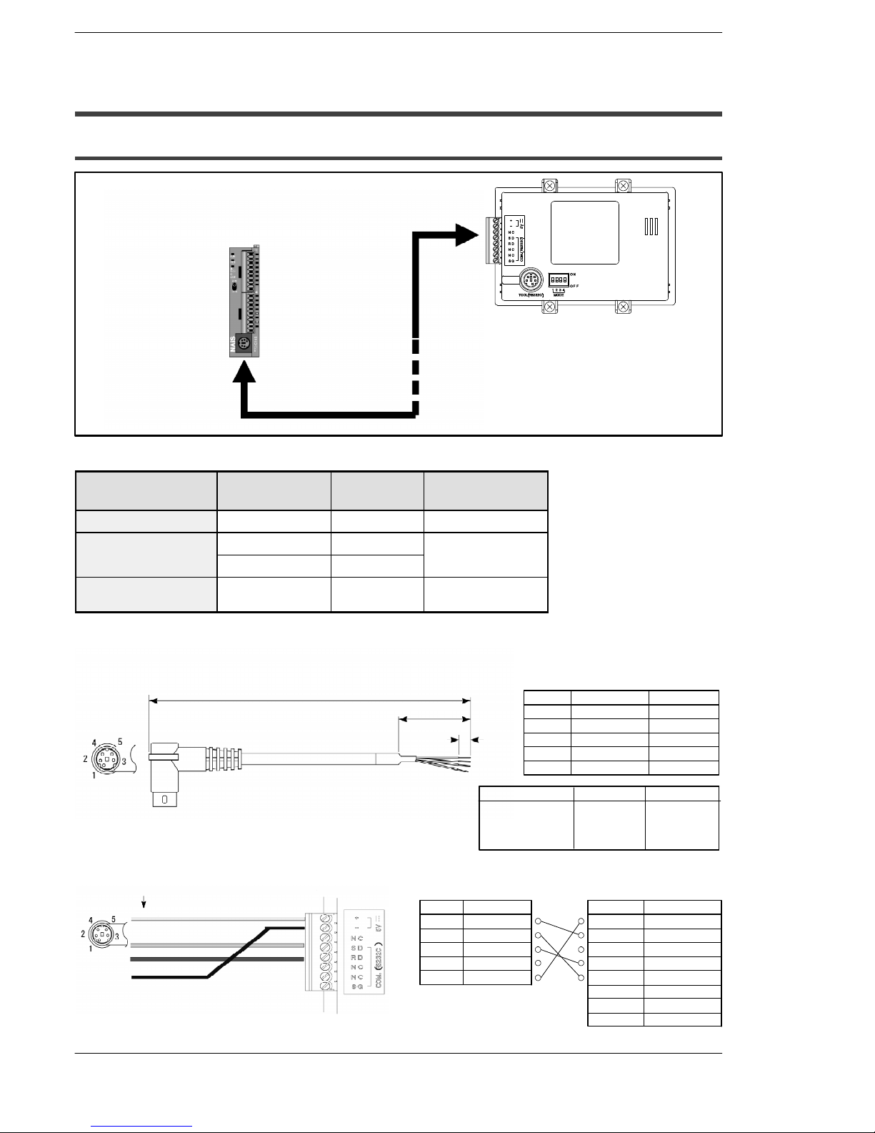
4.2 Connecting the FP0
4.2.1 Connecting to the TOOL Port
AIGT8142
FP0 TOOL port
GT01
FP0 communication format settings
System register no. Item Value Set System register
value
410
Unit number 1 K1
411
Data length 8 bits H0
Modemconnection No connection
414
Baud rate setting 19200 bits/s H010X
X is 0 to 6
PLC communication cable: Mini-DIN 5-pin loose-wire cable (AIGT8142)
7/0.28
30/1.18
2000/78.74
Mini-DIN plug side signals
1 SG Brown
2 SD Red
3 RD Orange
4-- -5 +5V White
Pin no. Abbreviation Wire color
Specifications L Product No.
2 m/6.56 ft
Mini-DIN 5-pin
Single-side
4 loose wires
AIGT8142
Connecting to the FP0 TOOL port
GT01
No. 1 (brown)
Pin no. on PLC side
No. 3 (orange)
No. 2 (red)
PLC side
Pin no.
Abbreviation
1SG
2SD
3RD
4-5 +5V
Abbreviation
GT main unit side
Pin no.
1+
23NC
4SD
5RD
6NC
7NC
8SG
No. 5 (White)
←To set 19200 bits/s for both
the COM. port and the TOOL
port, “H0100” should be set.
Page 51
Connecting and Communicating with the PLC
GT series
31
4.3 Connecting the FP2/FP2SH
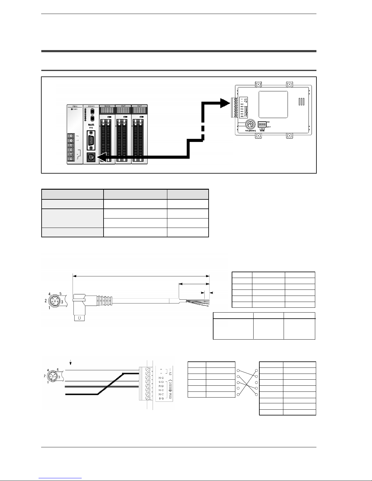
4.3 Connecting the FP2/FP2SH
4.3.1 Connecting to the TOOL Port
AIGT8142
FP2/FP2SH CPU TOOL port
GT01
FP2/FP2SH communication format settings
System register no. Item Value Set
410
Unit number 1
Data length 8 bits
4
1
1
Modem connection No connection
414
Baud rate setting 19200 bits/s
PLC communication cable: Mini-DIN 5-pin loose-wire cable (AIGT8142)
7/0.28
30/1.18
2000/78.74
Mini-DIN plug side signals
1 SG Brown
2 SD Red
3 RD Orange
4-- -5 +5V White
Pin no. Abbreviation Wire color
Specifications L Product No.
2 m/6.56 ft
Mini-DIN 5-pin
Single-side
4 loose wires
AIGT8142
Connecting to the FP2/FP2SH TOOL port
GT01
No. 1 (brown)
Pin no. on PLC side
No. 3 (orange)
No. 2 (red)
PLC side
Pin no.
Abbreviation
1SG
2SD
3RD
4-5 +5V
Abbreviation
GT main unit side
Pin no.
1+
23NC
4SD
5RD
6NC
7NC
8SG
No. 5 (White)
Page 52
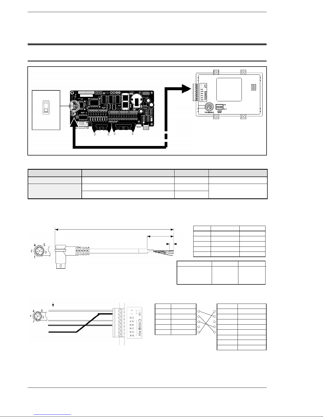
GT series
Connecting and Communicating with the PLC
32
4.4 Connecting the FP-M
4.4 Connecting the FP-M
4.4.1 Connecting to the TOOL Port
19200
AIGT8142
GT01
FP-M TOOL port
FP-M communication format settings
System register no. Item Value Set System register value
410
Unit number 1 K1
411
Data length 8 bits
H0
Modem connection No connection
PLC communication cable: Mini-DIN 5-pin loose-wire cable (AIGT8142)
7/0.28
30/1.18
2000/78.74
Mini-DIN plug side signals
1 SG Brown
2 SD Red
3 RD Orange
4-- -5 +5V White
Pin no. Abbreviation Wire color
Specifications L Product No.
2 m/6.56 ft
Mini-DIN 5-pin
Single-side
4 loose wires
AIGT8142
Connecting to the FP-M TOOL port
GT01
No. 1 (brown)
Pin no. on PLC side
No. 3 (orange)
No. 2 (red)
PLC side
Pin no.
Abbreviation
1SG
2SD
3RD
4-5 +5V
Abbreviation
GT main unit side
Pin no.
1+
23NC
4SD
5RD
6NC
7NC
8SG
No. 5 (White)
Page 53
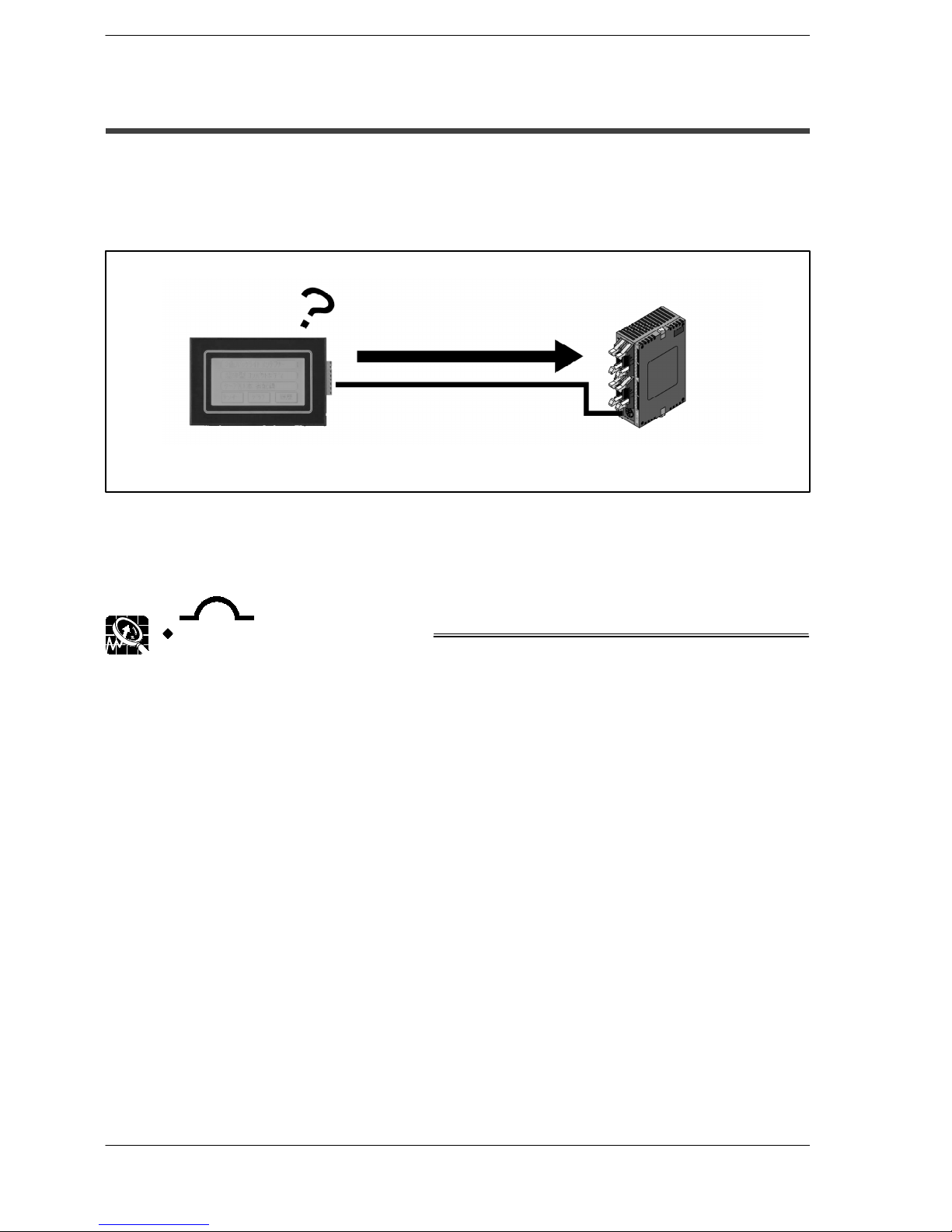
Connecting and Communicating with the PLC
GT series
33
4.5 Automatic Communication Settings Function
4.5 Automatic Communication Settings Function
After turning on the power supply, if there is no response from the PLC connected to
the GT01, the GT01 switches to the automatic setting mode for the communication
conditions. In the automatic setting mode, commands are sent to the PLC while
changing the communication conditions in the sequence shown below.
GT01
PLC
(1) 9600 bits/s, 8 bits, odd parity, 1 stop bit
(2) 19200 bits/s, 8 bits, odd parity, 1 stop bit
(3) 115200 bits/s, 8 bits, odd parity, 1 stop bit
(4) Communication conditions set in GTWIN Configuration Settings
If there is no response from the PLC,
commands are sent to the PLC while
changingthe communicationconditions.
The GT01, in automatic setting mode, continues to repeat steps (1) to (4) until there is
a response from the PLC. While it is repeating these steps, it is in the “Standby” mode
under “GT01 Configuration” a“Communication Parameters” a “Handle Communication
Error” onGTWIN. For information on how settingsare entered, please refer to page 43.
Explanation of this function
•
Conditions when the automatic settings mode is in effect
If communication is attempted the specified number of times and
there is no response from the PLC, the GT01 goes into the automatic
settings mode. The number of attempts is specified using the “No. of
Retries” parameter under “GT01 Configuration” → “Communication
Parameters” → “Handle Communication Error” on GTWIN. For
information on how settings are entered, please refer to page 43.
•
Automatically set communication conditions
In the automatic settings mode, if there is a response from the PLC,
subsequent communication is carried out under conditions matching
the response. The main unit configuration settings are not updated,
however, even if the communication parameters are different from
those of the main unit configuration settings.
Page 54

GT series
Connecting and Communicating with the PLC
34
4.5 Automatic Communication Settings Function
CAUTION
•
An error response from the PLC is taken as a response, and the GT01
does not go into the automatic settings mode.
•
If the unit is connected to the COM port of the
FP0/FP1/FP2/FP2SH/FP-M, communication between the FP device
and the PLC will not be possible if the target usage of the RS232C
port has been set to “Computer Link”. Always set the setting on the
PLC side to match “Computer Link”. For detailed information, please
refer to Chapter 4, “Connecting and Communicating with the PLC”,
on page 27.
Page 55
Connecting and Communicating with the PLC
GT series
35
4.6 Through Function
4.6 Through Function
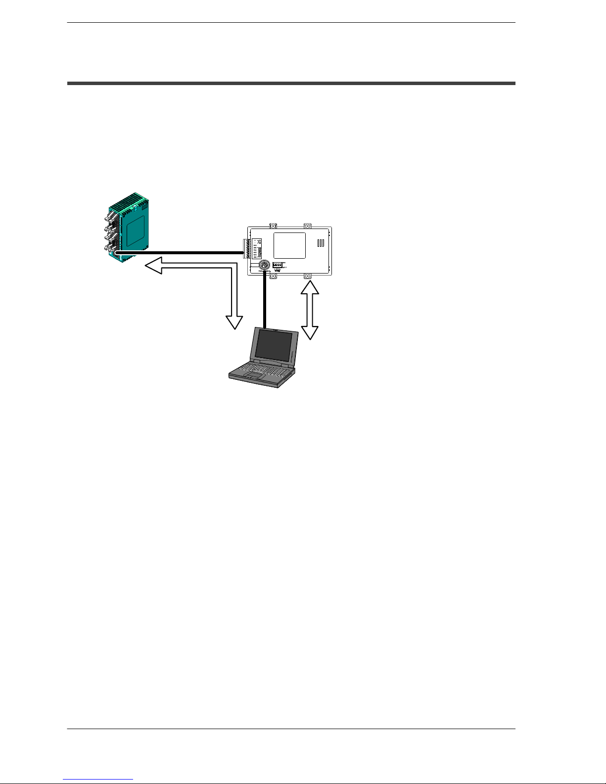
With the GT series, communication can be set to take place automatically between the
COM. and TOOL ports in a “through function”. When the FP series tool software
installed in the computer connected to the GT series as shown below is booted, PLC
programs can be edited through the GT series.
Thethrough functiondoes not require any special settings, andis alwaysin the standby
mode.
PLC
GT01
Connected by cable
to the TOOL port of
the PLC
Screen
transfer
cable
AFC8503
Screen data
being sent
and received
Screen creation tool GTWIN
FP series programming tool FPWIN GR
Personal computer
The FPWIN GR can booted on the computer being used to edit the GT series
screens, and the PLC programs can be
edited and monitored through the GT
series.
PLC debugging
Page 56
GT series
Connecting and Communicating with the PLC
36
4.6 Through Function
CAUTION
•
Precautions when using the through function
The system should be set up so that the interval for communication
retries in the FP series software (FPWIN GR or NPST-GR) (A) is larger
than that of the GT01 COM. port (B), meaning (A) > (B). If the system
is set up so that A = B or A < B, the through function will not work
properly.
•
Restrictions on COM. port connections
When connecting the GT01 to the COM port of a PLC, a separate
external DC 5 V power supply must be provided. Be sure to
remember this.
•
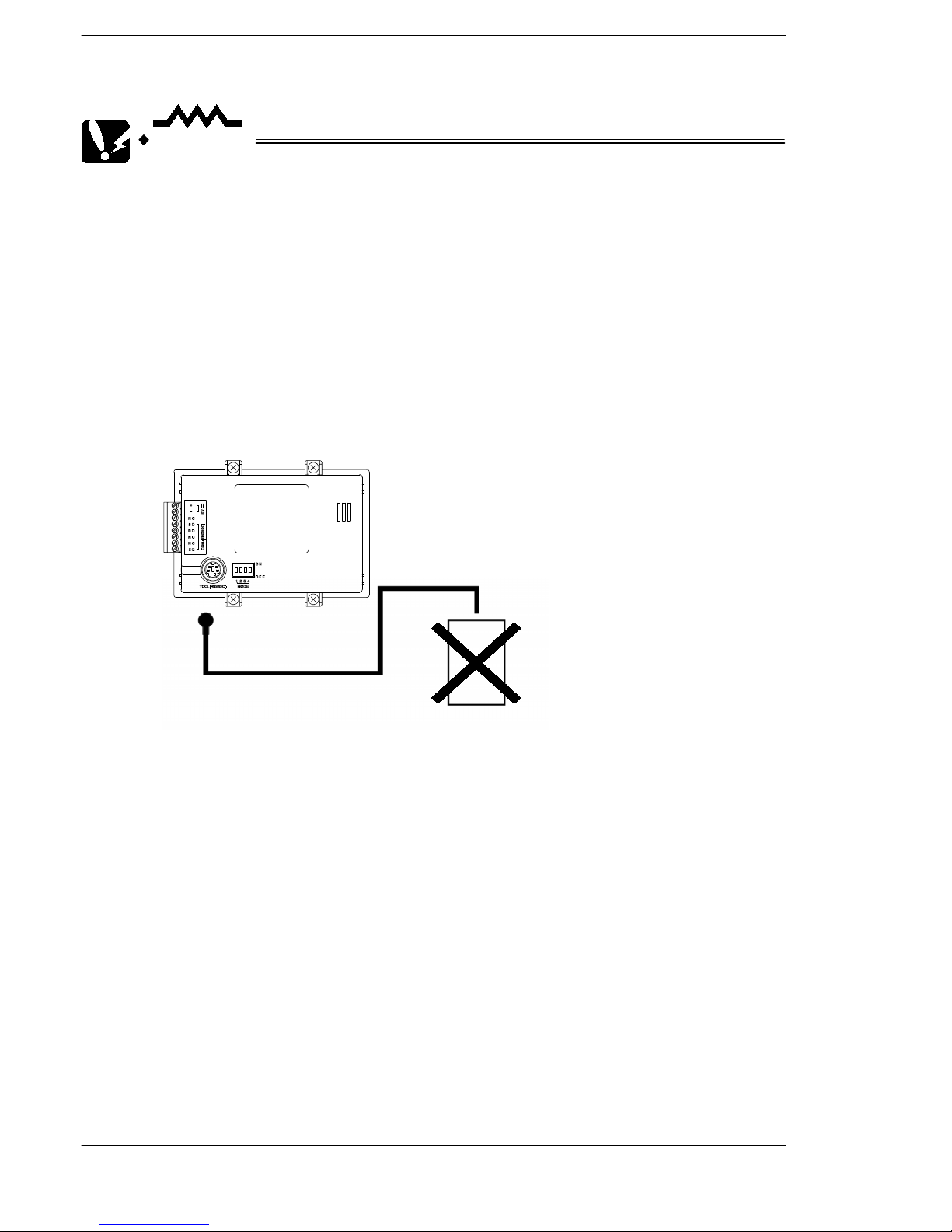
An FP Programmer II cannot be connected to the tool port.
FP Programmer II
Page 57

Chapter 5
GT01 Configuration Settings
Page 58

GT seriesGT01 Configuration Settings
38
Page 59
GT01 Configuration SettingsGT series
39
5.1 GT01 Configuration Settings
5.1 GT01 Configuration Settings
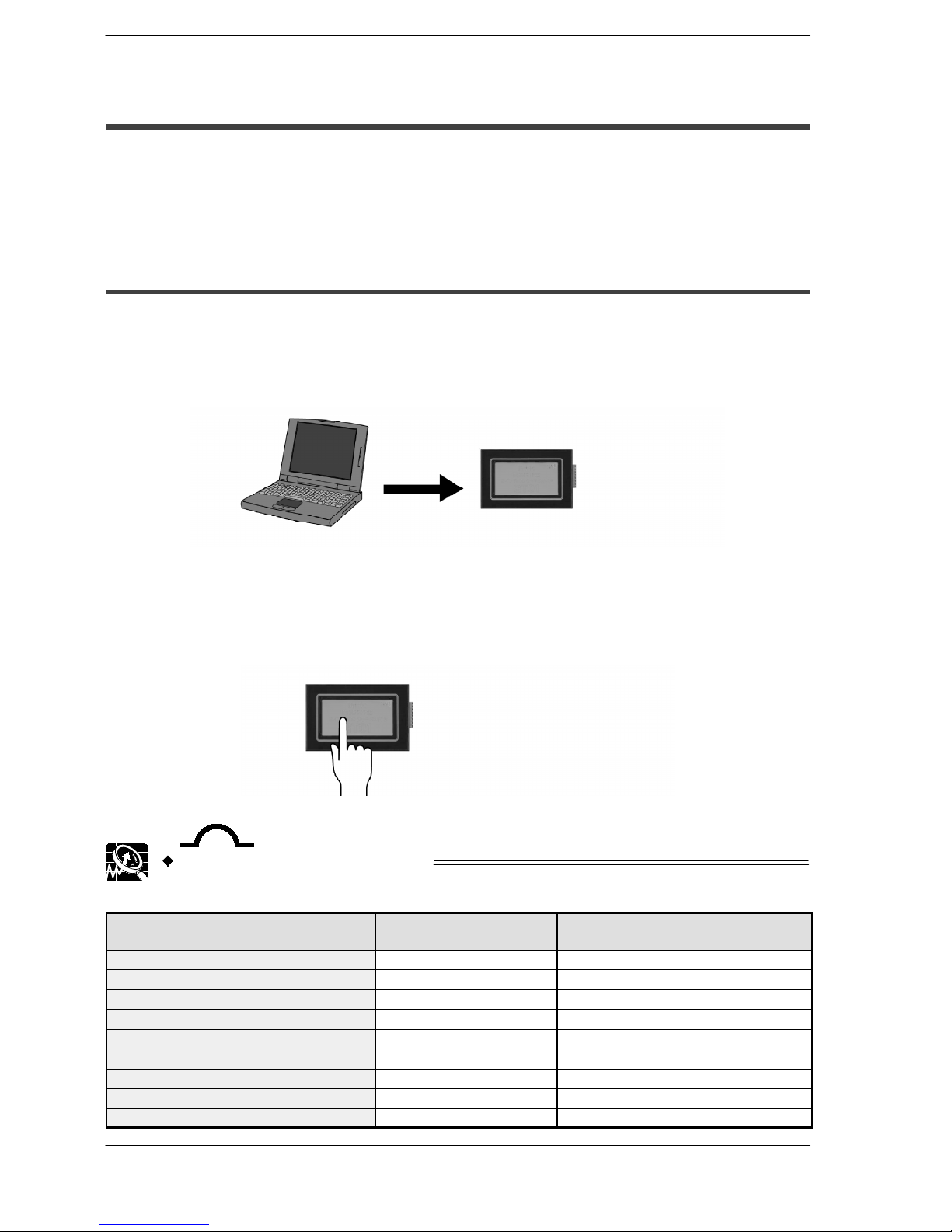
Before using the GT01 for the first time, it must be set up by entering the GT01
configuration settings indicated below . Always check and enter the settings under “Basic
communication area to PLC”. For instructions on setting up the GT01, see page 24.
5.1.1 Two Types of GT01 Configuration Settings
1. Entering configuration settings from GTWIN screen creation tool page 40..
Withthis method, GT01configuration settings areentered from GTWIN screen creation
tool, and the GT01 configuration file is sent to the GT01. Most items can be set using
this method.
GTWIN
GT01
configuration
file sent
2. Entering configuration settings from the GT01 main unit page 52..........
Some of the settings, such as the communication parameters, the internal clock, and
adjustments of the liquid crystal display contrast, can be set using the system menu of
the GT01. Settings are entered using the touch switches on the front of the panel.
GT01
Explanation of this function
Items in the GT01 Configuration Settings
Items that can be set from GTWIN
Items that can be set
either way
Items that can be set from the
GT01 system menu
Title setting
Communication parameters LCD contrast setting
Type of PLC connected
Communication parameters
Basic communication area to PLC
Memory initialization
Communication parameters
Self-diagnosis
Auto-paging screen settings
Startup screen (default screen) settings
Reference destination setting for clock
Backlight control
Touch sounds
Page 60
GT series
GT01 Configuration Settings
40
5.2 Entering Configuration Settings from GTWIN Screen Creation Tool
5.2 Entering Configuration Settings from GTWIN Screen
Creation Tool
Thissectiondescribeshowconfigurationsettingsfor the GT01areenteredfromGTWIN
screen creation tool.
5.2.1 Opening the GT Configuration Settings
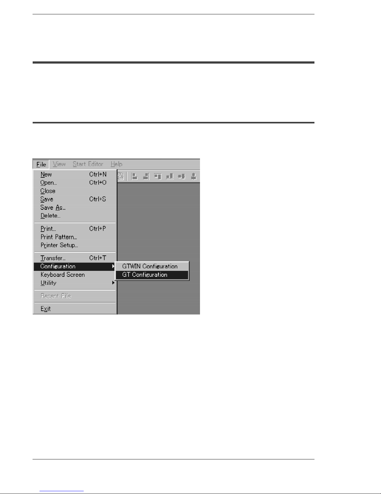
The GT configuration settings are set by selecting [Configuration] on the menu
displayed by clicking with the mouse on [File] or pressing the Alt + F keys. Then select
the “GT Configuration” sub-menu under [Configuration].
Configuration Settings
GTWIN Configuration - - - These are operating environment settings for GTWIN.
GT Configuration -- - These are configuration settings for the GT01. The file is sent
from GTWIN to the GT01 after the settings have been entered.
Page 61
GT01 Configuration Settings
GT series
41
5.2 Entering Configuration Settings from GTWIN Screen Creation Tool
5.2.2 GT Configuration Settings: “Basic Setup”
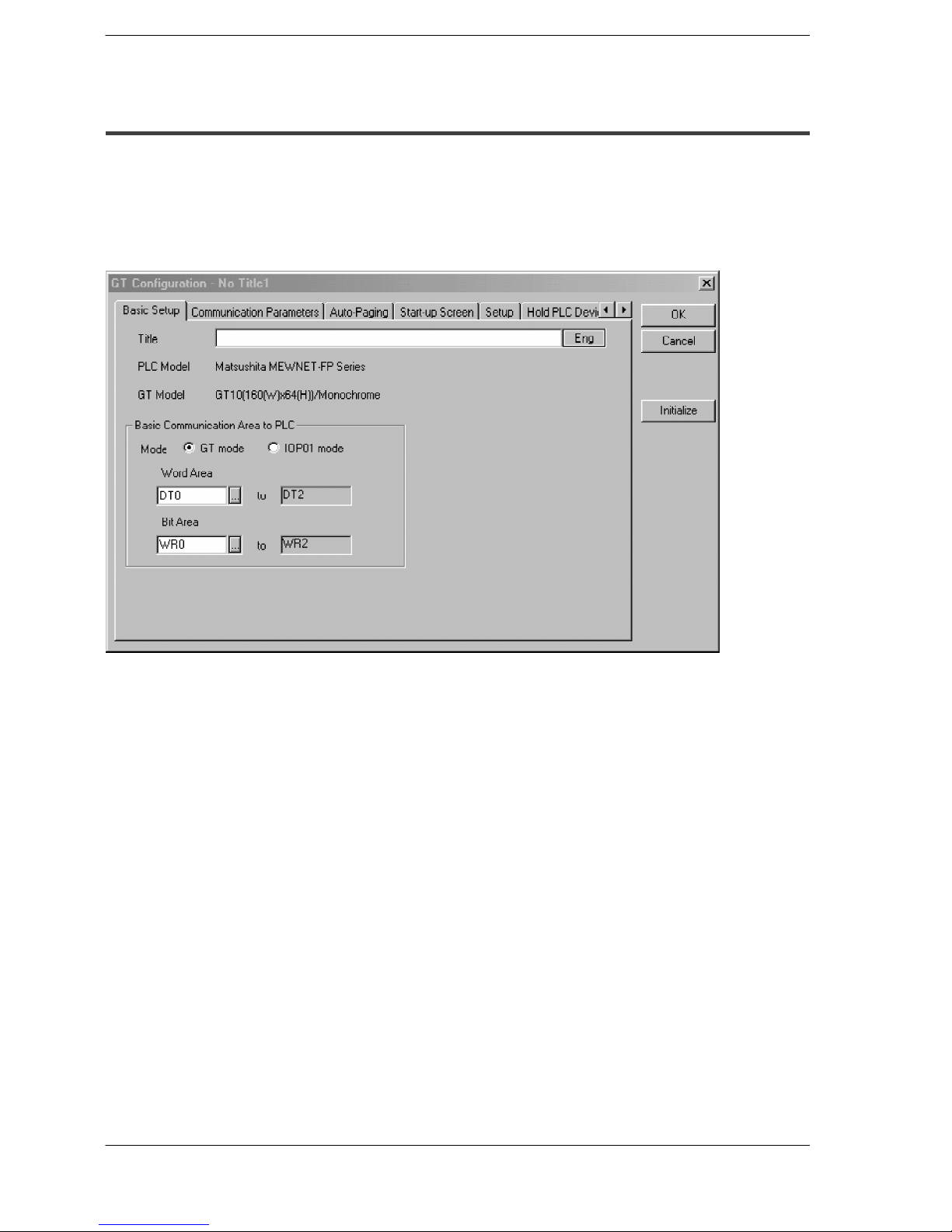
Selecting [Configuration] on the [File] menu of GTWIN and then the sub-menu [GT
Configuration] displays the “Basic Setup” screen shown below.
This is used to specify the basic communication area used for communication between
the GT01 and PLC, and the environment required for GT01 operation.
“Basic Setup” screen
Title -- - The title of the configuration settingsfile is entered here. Titles are convenient
if each GT01 has its own configuration settings.
PLC Model - - - The model of PLC specified when GTWIN is booted is displayed here.
GT Model - - - The model of GT specified when GTWIN is booted is displayed here.
Basic communication area to PLC
Thisisused to specifythemode inwhichcommunicationtakes place between theGT01
and PLC, and the internal PLC device used for basic communication.
Page 62
GT series
GT01 Configuration Settings
42
5.2 Entering Configuration Settings from GTWIN Screen Creation Tool
Device used
Thisspecifies the internal PLC deviceused forbasic communicationbetweenthe GT01
and PLC.
·
Word area - - - This specifies the type of device that reads and writes screen
numbers and other information in word units, and the initial address.
·
Bit area - - - This specifies the type of device that reads and writes backlight
control and other bit information, and the initial address.
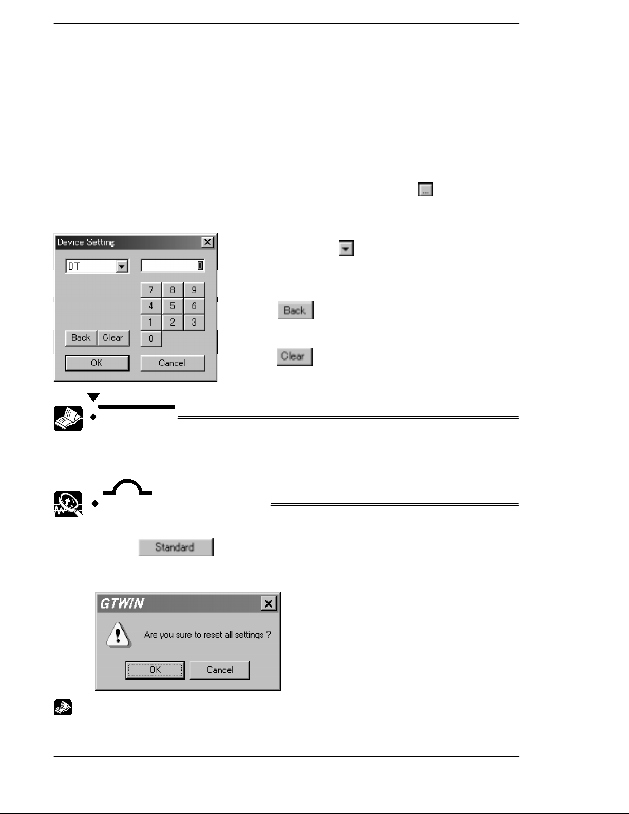
The type of device and addresses can be set by clicking on the
buttons for the
various items.
Device settings dialog box
Clicking on the button displays a pull-down
menu. Select the device for which settings are
to be entered, and use the ten-keys to enter
addresses.
The button functions as a backspace
key when entering addresses.
The button acts as a Clear key.
REFERENCE
For detailed information on the basic communication area map, see
“GT01 Basic Communication Area Map” on page 26.
Explanation of this function
Standard settings
Clicking on the
button in the “GT Configuration” dialog box displays the
following message. Clicking on [OK] sets the default values (the configuration settings
entered when the unit is shipped) for all of the settings.
For information on the contents of configuration settings entered when the unit is
shipped, see “Contents of configuration settings for GT01 when shipped from the
factory” on page 21.
Page 63
GT01 Configuration Settings
GT series
43
5.2 Entering Configuration Settings from GTWIN Screen Creation Tool
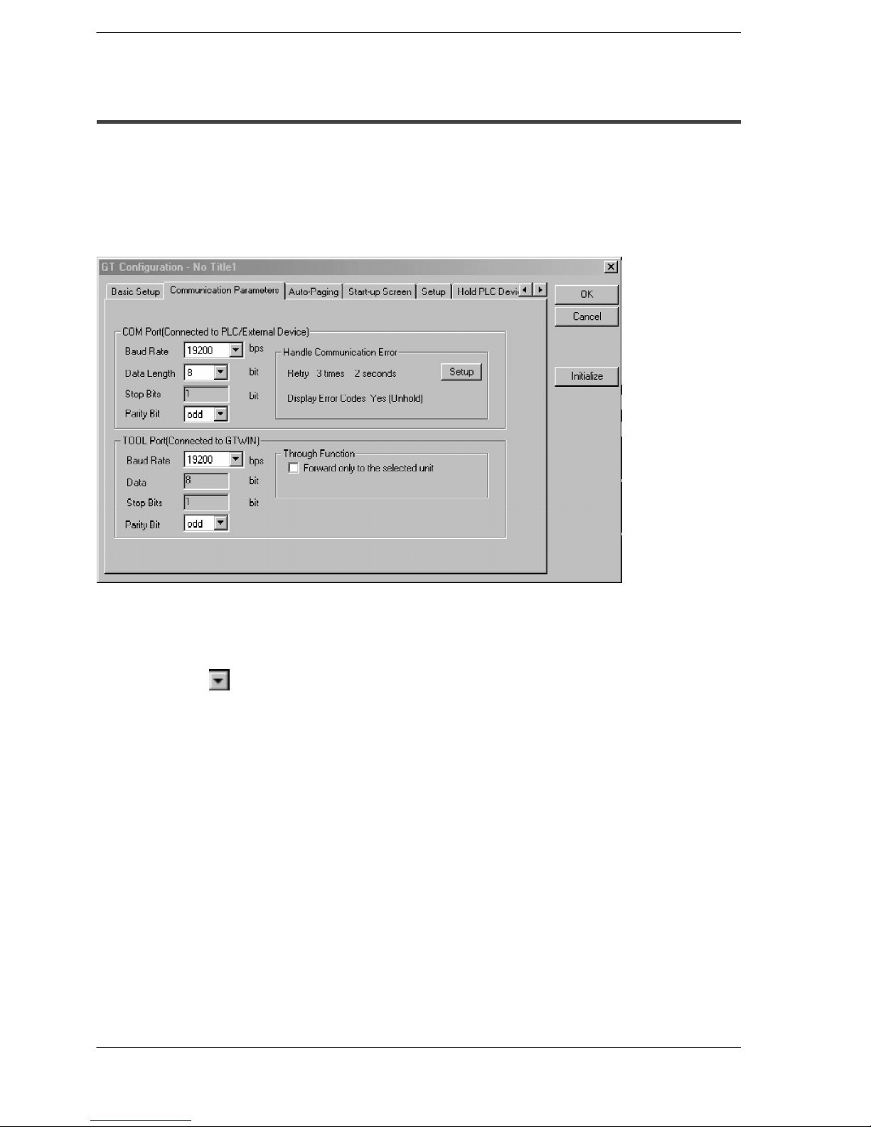
5.2.3 GT Configuration Settings: “Communication Parameters”
Clicking on the “Communication Parameters” tab in the “GT Configuration” dialog box
displays the following screen.
This is where communication parameters for the PLC and personal computer (GTWIN)
connected to the GT01 are set.
“Communication Parameters” screen
COM. port (Connected to PLC/External Device)
This is used to specify the communication speed and transmission format when the
GT01 is connected to an external device (PLC).
Clickingon the
buttondisplays apull-down menu from which the value to be setcan
be selected.
·
Baud Rate - - - Select 9600, 19200, 38400, 57600, 76,800 or 115200 bits/s.
·
Data Length - - - Select either “7 bits” or “8 bits”.
·
Stop Bits - - - This is fixed at “1 bit”.
·
Parity Bit - - - Select “None”, “Odd”, or “Even”.
Page 64
GT series
GT01 Configuration Settings
44
5.2 Entering Configuration Settings from GTWIN Screen Creation Tool
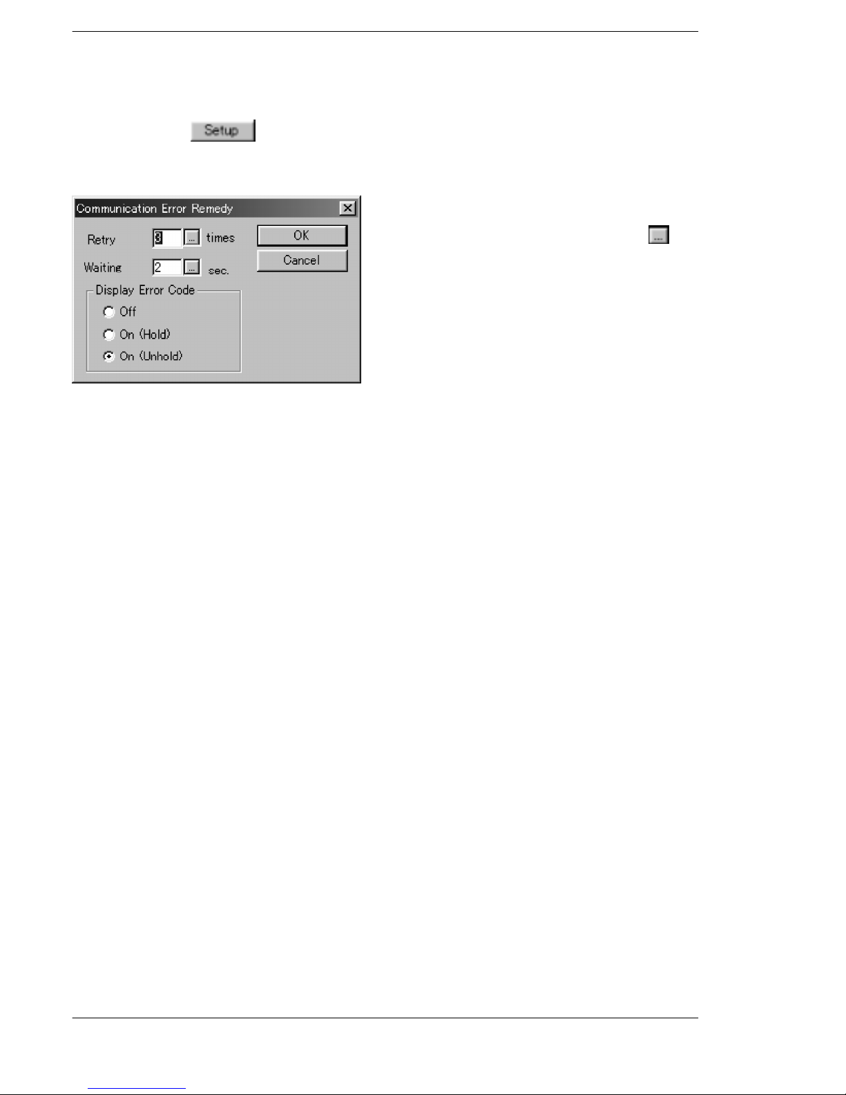
Handle Communication Error
Clicking on the
button displays the “Communication Error Remedy” dialog
box. This is used to specify the processing to be used if a communication error occurs.
“Communication Error Remedy” dialog box
For “Retry” and “Waiting”, click the
button and specify the values in the
“Value Set” dialog box that is displayed.
For “Display Error Code”, select “Off”,
“On (Hold)”, or “On (Unhold)” by clicking the radio button of the desired value to turn it on.
Retry - - - This specifies the number of retries if a communication error occurs. The
setting range is from 0 to 255 times.
Waiting - - - This specifies the interval betweenretries ifa communication error occurs.
The setting range is from 0 to 255 seconds.
Page 65

GT01 Configuration Settings
GT series
45
5.2 Entering Configuration Settings from GTWIN Screen Creation Tool
“Display Error Code”
This switches the setting for the error code display used if a communication error
occurs.
Off -- - No error code is displayed if a communication error occurs.
On (Hold) - - - An error code is displayed at the upper right of the screen if a
communication error occurs, and continues to be displayed until the power supply is
turned off.
On (Unhold) - - - An error code is displayed at the upper right of the screen if a
communication error occurs, and is cleared when the cause of the error is eliminated.
For contents of error codes, please see “Error Codes and How to Handle Them”
on page 78.
TOOL Port (for GTWIN connection)
This is used to specify the communication speed and transmission format when the
GT01 is connected to a personal computer (GTWIN).
Clickingon the
buttondisplays apull-down menu from which the value to be setcan
be selected.
·
Baud Rate - - - Select 9600, 19200 or 115200 bits/s.
·
Data Length - - - This is fixed at “8 bits”.
·
Stop Bits - - - This is fixed at “1 bit”.
·
Parity Bit - - - Select “None”, “Odd”, or “Even”.
Through function
If the “Forward only to the selected unit” check box is turned on, communication can be
carried out via the through function only with unit numbers for a PLC received from a
higher-order personal computer or higher-order PLC.
Page 66
GT series
GT01 Configuration Settings
46
5.2 Entering Configuration Settings from GTWIN Screen Creation Tool
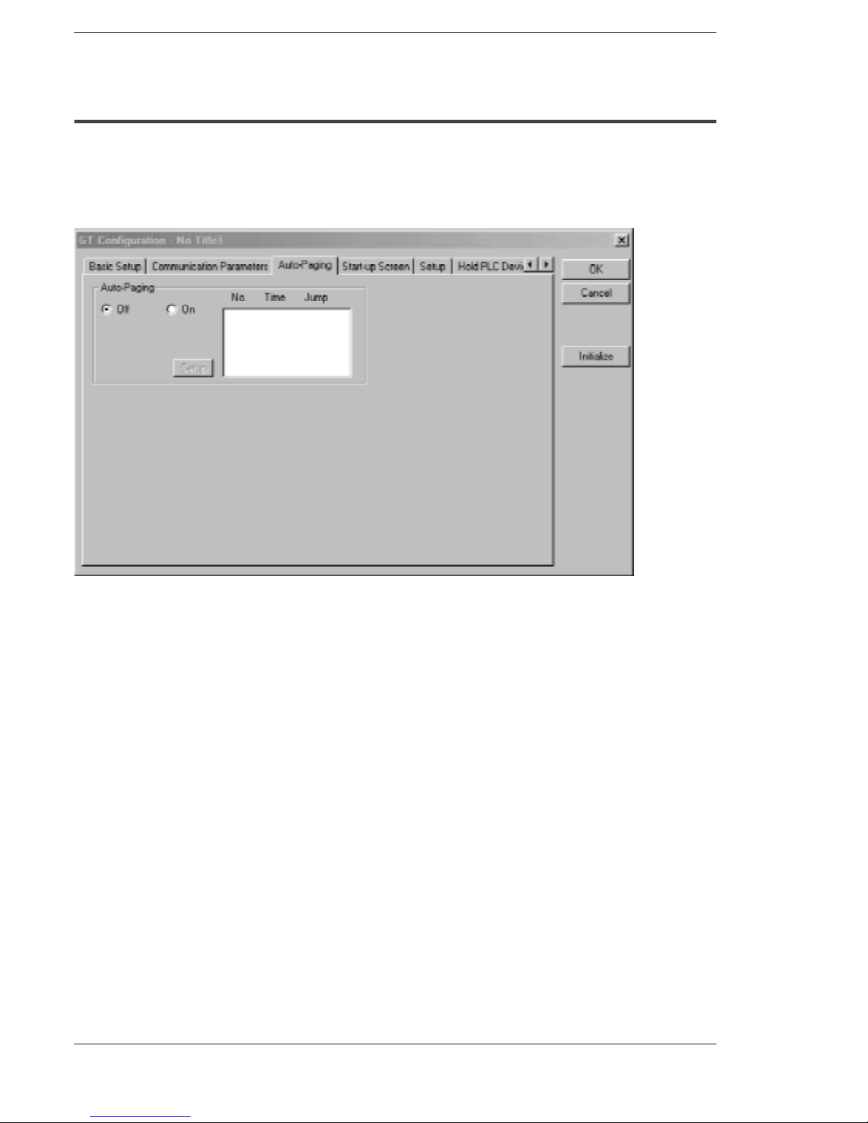
5.2.4 GT Configuration Settings: “Auto-Paging”
Clicking on “Auto-Paging” in the “GT Configuration” dialog box displays the screen
shown below.Here, settings can be entered for a functions that automatically switches
the screens displayed on the GT01.
“Auto-Paging” screen
Auto-paging
This is used to specify the “Auto-paging function”, which automatically switches the
specified screen when a given period of time has elapsed.
Off -- - The screen is not switched automatically.
On - - - The screen is switched automatically, in conformance with the specified
contents.
Page 67
GT01 Configuration Settings
GT series
47
5.2 Entering Configuration Settings from GTWIN Screen Creation Tool
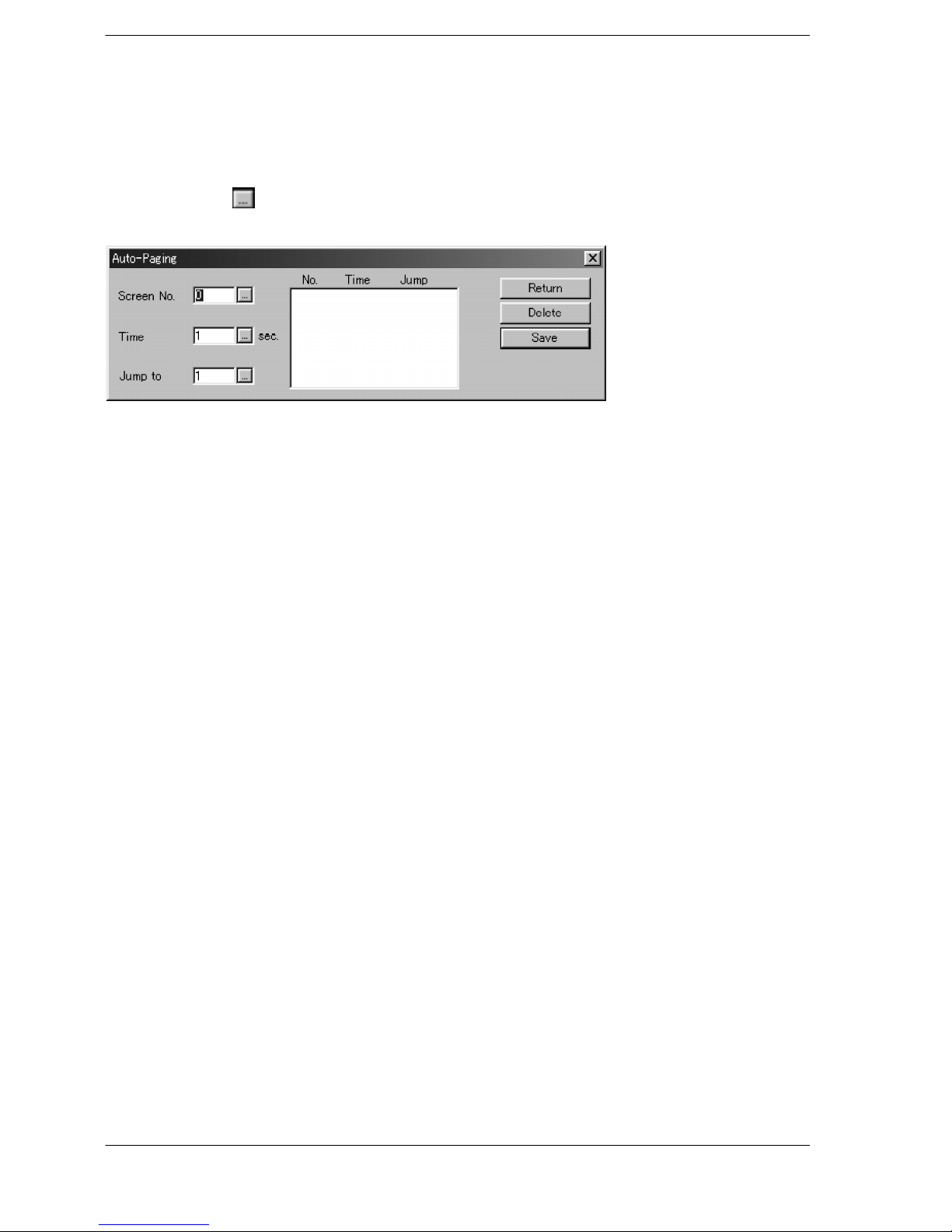
Auto-paging settings
If “On” is selected for auto-paging, and the [Setup] button is clicked, a dialog box
containing the following auto-paging settings is displayed.
Clicking on the
button for “Screen No.”, “Time”, or “Jump to” displays a “Value Set”
dialog box. Set the value and click the [Save] button to save values one at a time.
Screen No. - - - This specifies the screen targeted for auto-paging.
Time - - - This specifies the time for which the screen specified above is displayed.The
setting range is from 1 to 255 seconds.
Jump to - - - This specifies the number of the next screen to be displayed.
[Return] - - - This completes the auto-paging settings and returns to the
“Auto-Paging” dialog box.
[Delete] -- - This deletes screens registered for auto-paging.
[Save] -- - This saves the settings for the screen number, time, and jump destination
as auto-paging settings.
Page 68
GT series
GT01 Configuration Settings
48
5.2 Entering Configuration Settings from GTWIN Screen Creation Tool
5.2.5 GT Configuration Settings: “Startup Screen Settings”
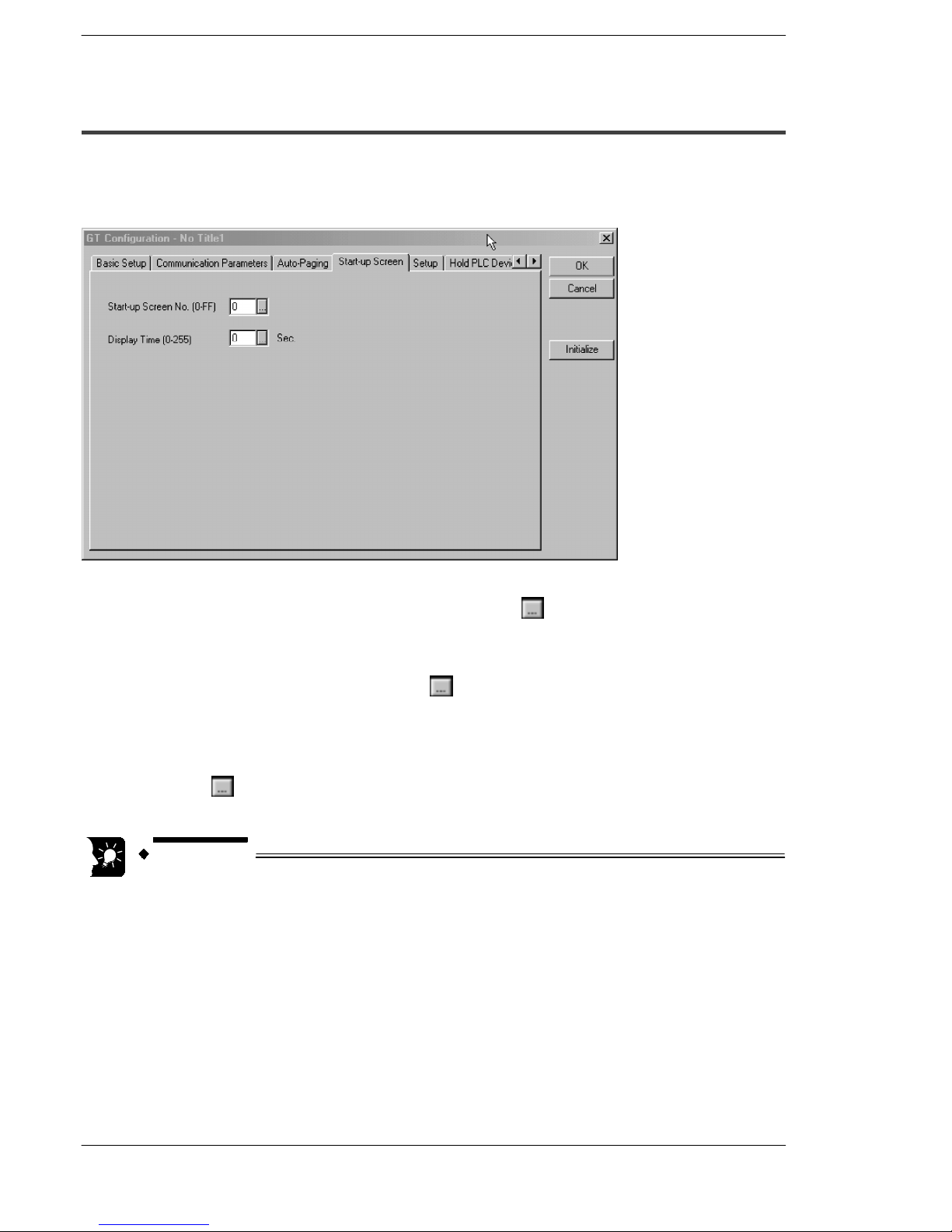
Clicking on “Start-up Screen” in the “GT Configuration” dialog box displays the screen
shown below. Here, the screen displayed when the GT01 is booted can be specified.
“Start-up Screen” screen
This is used to specify the screen that will be displayed when the GT01 is booted, as
well as the time it will be displayed. Clicking on the
button for each of the items
displays a “Value Set” dialog box where the values can be specified.
Start-up Screen No. - - - This specifies the number of the screen that will be displayed
when the GT01 is booted. Clicking on the
button displays a “Value Set” dialog box
where the value for the start-up screen number can be specified.
Display Time -- - This specifies the time for which the startup screen specified above
will be displayed. The value can be set to any number between 0 and 255 seconds.
Clicking on the
button displays a “Value Set” dialog box where the start-up delay
time can be specified.
Key points
•
When the above settings are entered, the screen specified with the
“Startup Screen No.” parameter is displayed for the amount of time
specified with the “Display Time” parameter.
•
When the amount of time specified with the “Display Time” parameter
elapses, the screen corresponding to the number stored in the initial
address of the word device under “Basic Communication Area to
PLC” in the “Basic Setup” parameters under “GT Configuration” will
be displayed.
•
This function is used when it is necessary to delay the start-up time
when the power supply on the PLC side is turned on.
Page 69

GT01 Configuration Settings
GT series
49
5.2 Entering Configuration Settings from GTWIN Screen Creation Tool
CAUTION
•
Communication between the GT01 and the PLC (external device)
cannot be carried out during the time specified by the “Display Time”
parameter.
Page 70
GT series
GT01 Configuration Settings
50
5.2 Entering Configuration Settings from GTWIN Screen Creation Tool
5.2.6 GT Configuration Settings: “Setup”
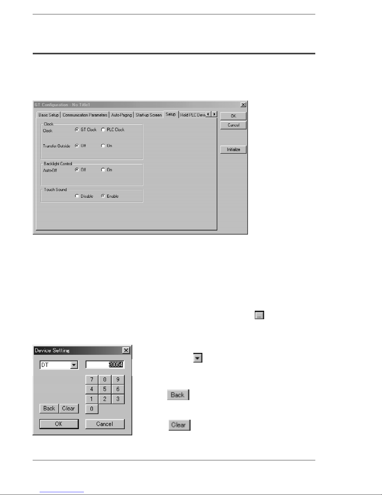
Clicking on the “Setup” tab in the “GT Configuration” dialog box displays the screen
shown below. Here, clock functions, backlight control, and other parameters can be
specified.
“Setup” screen
Clock
Clock
This is used to specify the reference destination for the clock displayed with the GT01.
Select one of the radio buttons.
PLC Clock - - - When the time is displayed, the internal clock in the PLC is used as a
reference for the value.
If the “PLC Clock” is referenced for the clock setting, clicking on the
button displays
a screen where the type of device and the address can be specified.
Device Setting dialog box
The button functions as a backspace
key when entering addresses.
The button acts as a Clear key.
Click on the button to display the pull-down
menu, and select the device from that menu.
Enter the address using the ten-keys.
Page 71

GT01 Configuration Settings
GT series
51
5.2 Entering Configuration Settings from GTWIN Screen Creation Tool
Backlight control
Auto-Off
This is used to specify the Auto-Off backlight feature.
Off -- - The Auto-Off backlight feature is not used.
On - - - Auto-Off backlight feature is used. This parameter specifies the period of time
that the GT01 is inactive before the backlight goes off automatically.
If “On” is set forthe above Auto-Off backlight feature, clicking on the
buttondisplays
a screen where the time until the backlight goes off can be specified. Any time from one
minute to 30 minutes can be specified.
Key points
If the backlight is turned off automatically using the backlight control
function, touching the screen turns it on again. If a touch switch
happens to be located at that point on the screen, it will be invalid until
the backlight has gone on again.
Touch Sounds
This sets the touch sounds corresponding to GT01 screens as either invalid or valid.
Select one of the radio buttons.
Disable -- - Touch sounds are disabled.
Enable -- - Touch sounds are enabled.
Page 72
GT series
GT01 Configuration Settings
52
5.3 Entering Configuration Settings from the GT01 Main Unit
5.3 Entering Configuration Settings from the GT01 Main
Unit
5.3.1 What is the System Menu?
The system menu is a dedicated screen on which configuration settings for the GT01
are entered. Some of the items that can be specified here can also be set usingGTWIN
screen creation tool and then sent to the GT01, but others, such as the adjustments to
the LCD contrast level, can only be set using the system menu. This section explains
how configuration settings are entered using the system menu.
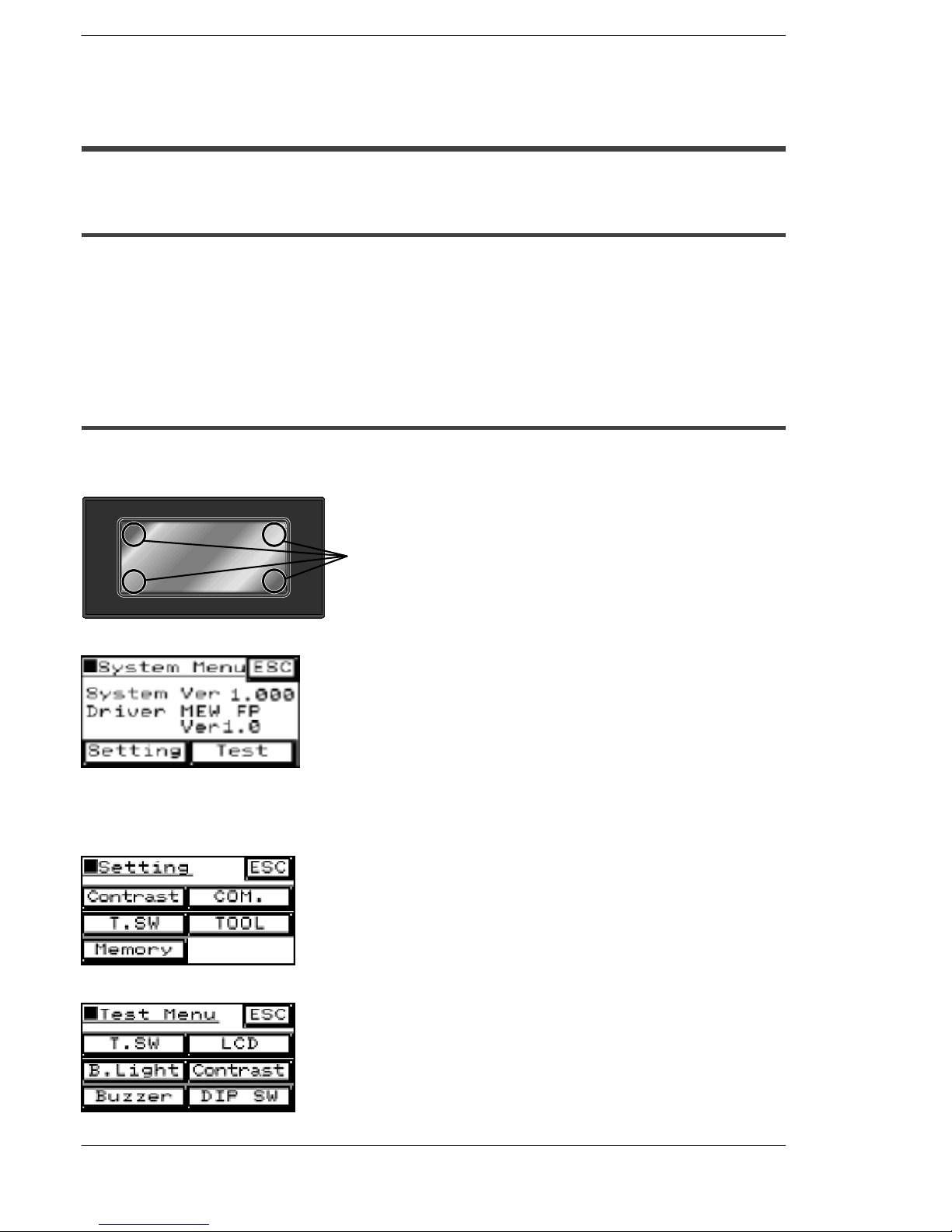
5.3.2 Bringing Up the System Menu
The following procedure is used to bring up the system menu.
(1) Touch the LCD touch panel simultaneously.
1. Press the top left corner (A) for more than one
second.
2. Next, immediately press the top right corner (B)
and the bottom right corner (C), in that order.
(2) The initial screen of the system menu is displayed.
The initial screen of the system menu is displayed on
the GT01. Touching either the [Setting] or [Test] key
shifts to the next screen.
Touching the [ESC] key exits the system menu and returns to the normal operating mode.
“System Ver” indicates the ROM version of the GT01 system.
(3) Select the mode.
[Setting]: Setting mode initial screen
This is where configuration settings for the GT01, such
as the contrast, clock, COM. port, TOOL port, and
memory, are specified.
[Test]: Test mode initial screen
This is where GT01 configuration elements such as
the touch switches, backlight, clock, buzzer, LCD,
contrast, and memory are tested.
Page 73
GT01 Configuration Settings
GT series
53
5.3 Entering Configuration Settings from the GT01 Main Unit
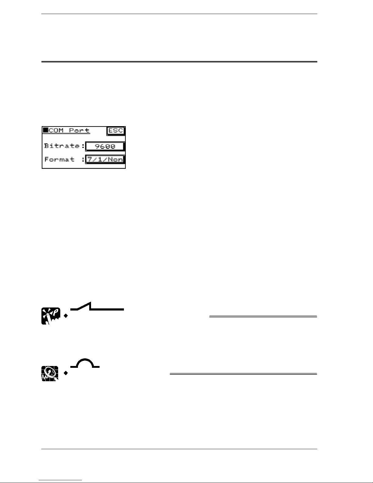
5.3.3 Setting Mode: “Communication Parameters”
(COM. Port / TOOL Port)
Touching the [Setting] key on the initial screen of the system menu and then
touching the [COM. Port] and [TOOL Port] keys on the setting mode menu displays
the communication parameters setting screen. Here, parameters controlling
communication between the PLC and personal computer (GTWIN) connected to the
GT01 are specified.
COM. port communication parameter settings (PLC communication parameter settings)
Procedure for bringing up the screen
[Initial screen]
[Setting]
[COM. port]
↓
↓
Bitrate: PLC communication speed
This sets the communication speed, or Baud rate, for communication with an external
device (PLC) connected to the GT01.
Each time the [Function] key is pressed, the Baud rate switches in the sequence of
9600, 19200, 38400, 57600, 115200 bits/s. Set the speed to match that of the PLC
connected to the GT01.
Format: Transmission format
This sets the communication parameters (data length, stop bits, parity) for the external
device (PLC) connected to the GT01.
Theitems displayed are: Data length/ Stopbit / Parity,and eachtime the [Function] key
is pressed, the display switches in the sequence of: [7/1/None], [7/1/Odd], [7/1/Even],
[8/1/None], [8/1/Odd], [8/1/Even]. Set the parameters to match those of the PLC
connected to the GT01.
Learning the shortcut keys saves time!
[RETURN]To complete the settings and return to the previous screen,
touch the [ESC] key.
Explanation of this function
COM. port communication parameter settings
The default (initial) values for the COM. port communication parameter
settings are: 19200 bits/s, 8/1/Odd.
Page 74
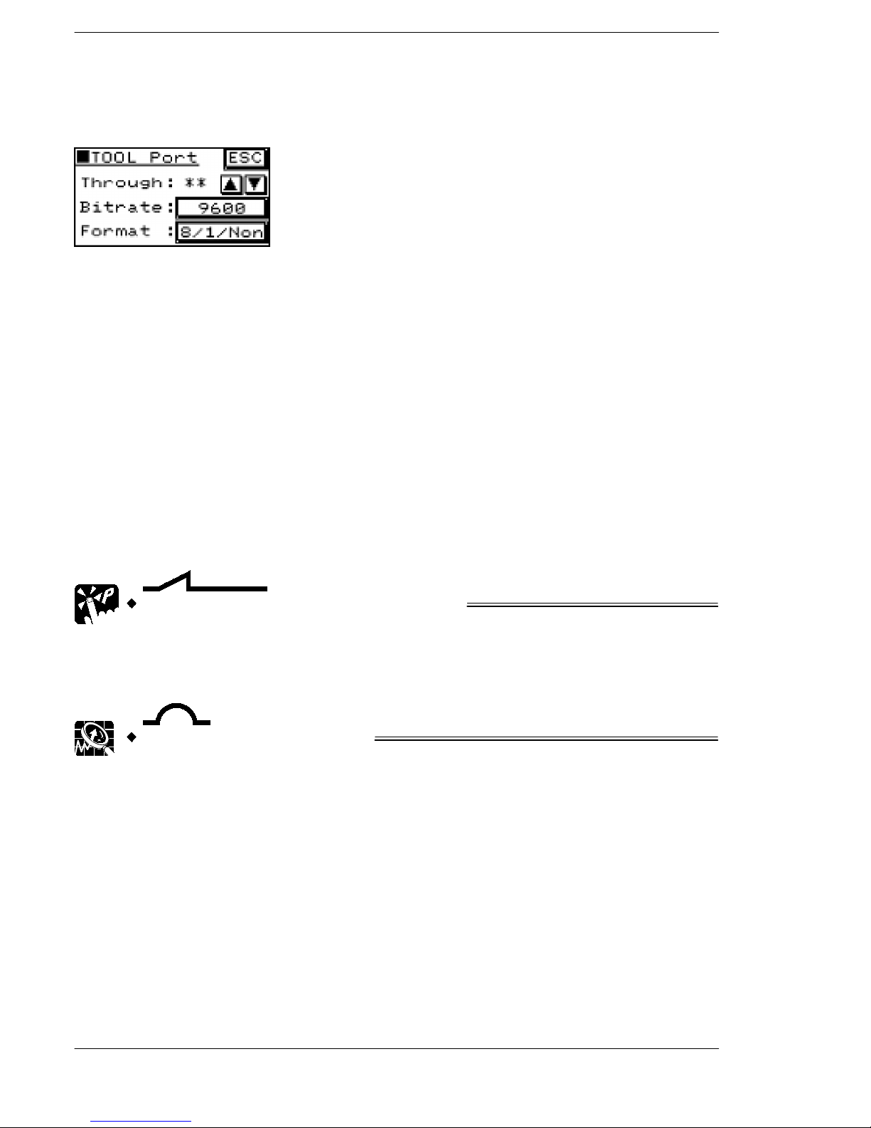
GT series
GT01 Configuration Settings
54
5.3 Entering Configuration Settings from the GT10 Main Unit
TOOL Port communication parameter settings (GTWIN communication parameter
settings)
Procedure for bringing up the screen
[Initial screen]
[Setting]
[TOOL Port]
↓
↓
Through function: Through function destination setting
When the through function is being used, this specifies the number of the PLC at the
other end of the connection. Normally, when used in a 1 : 1 configuration, this should
be set to “00”.
Bitrate: GTWIN communication speed
Each time the [Function] key is touched, the Baud rate switches in the sequence of
9600/19200/115200 bits/s. Set the speed to match that of the personal computer
(GTWIN) connected to the GT01.
Format: Transmission format
Thissets the communication parameters (data length, stop bits, parity)for the personal
computer (GTWIN) connected to the GT01.
Theitems displayed are: Data length/ Stopbit / Parity,and eachtime the [Function] key
is pressed, the display switches in the sequence of: [8/1/None], [8/1/Odd], [8/1/Even].
Learning the shortcut keys saves time!
[RETURN]To complete the settings and return to the previous screen,
touch the [ESC] key.
Explanation of this function
TOOL Port communication parameter settings
The default (initial) values for the TOOL Port communication parameter
settings are: 19200 bits/s, 8/1/Odd.
Page 75
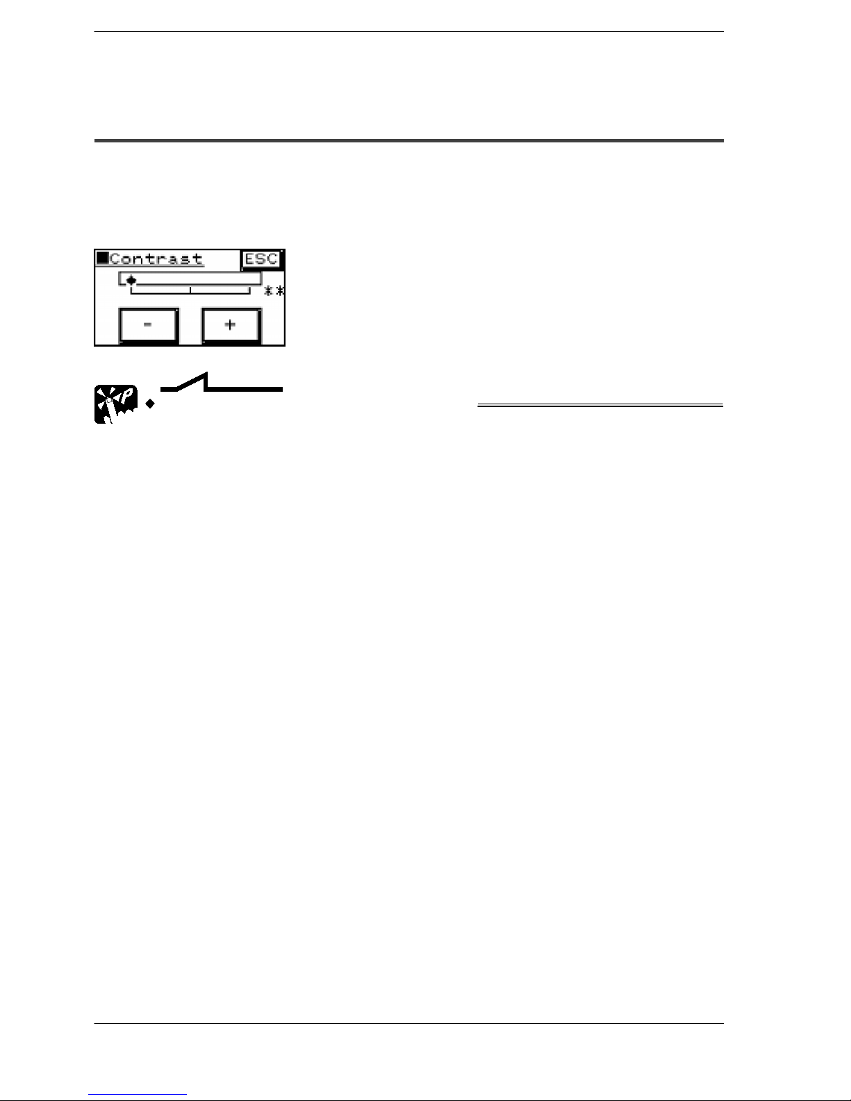
GT01 Configuration Settings
GT series
55
5.3 Entering Configuration Settings from the GT10 Main Unit
5.3.4 Setting Mode: “Liquid Crystal Display Contrast Adjustment”
(Contrast)
Touching [Setting] on the initial screen of the system menu and then the [Contrast] key
of the setting mode menu displays the contrast adjustment screen. The contrast of the
GT01 LCD is adjusted here.
Contrast adjustment screen
Procedure for bringing up the screen
[Initial screen]
[Setting]
[Contrast]
↓
↓
Learning the shortcut keys saves time!
[ADJUST] Touching the [+] key increases the contrast, and touching the
[-] key decreases it.
[RETURN]To complete the settings and return to the previous screen,
touch the [ESC] key.
Page 76
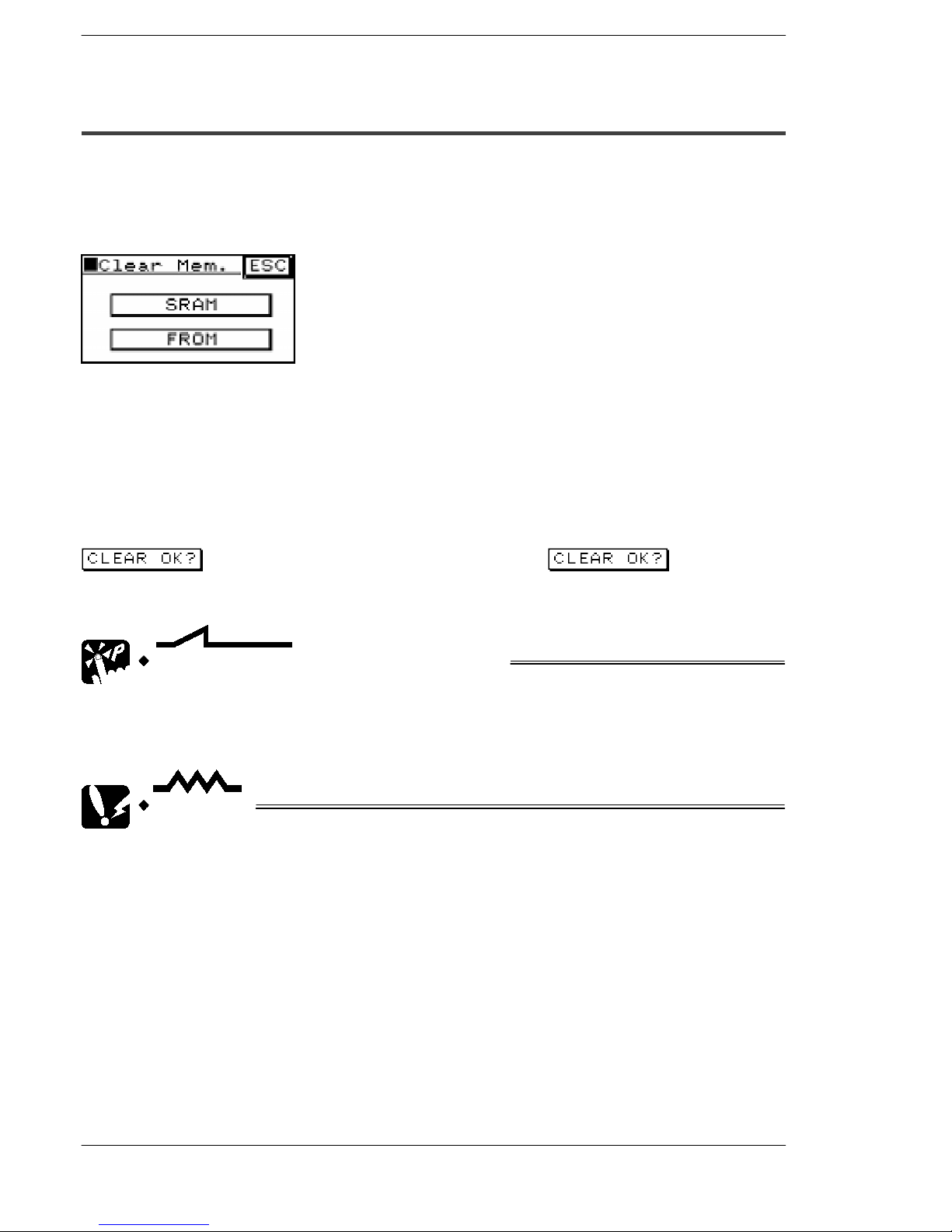
GT series
GT01 Configuration Settings
56
5.3 Entering Configuration Settings from the GT10 Main Unit
5.3.5 Setting Mode: “Memory Initialization” (Clear Memory)
Touching [Setting] on the initial screen of the system menu and then the [Memory] key
of the setting mode menu displays the memory initialization screen. The internal user
memory of the GT01 is initialized here.
Memory initialization screen
Procedure for bringing up the screen
[Initial screen]
↓
[Setting]
↓
[Memory]
Touching the [SRAM] key deletes clock data and Hold PLC Device data held in the
SRAM.
Touching the [FROM] key deletes screen data and main unit configuration settings
saved to the main unit user memory (F-ROM).
When either of the above keys is touched, a confirmation message reading
is displayed. To clear the data, touch the key. A buzzer
sounds, and the memory is cleared. When the buzzer stops sounding, the memory has
been completely cleared.
Learning the shortcut keys saves time!
[RETURN]To complete the settings and return to the previous screen,
touch the [ESC] key.
CAUTION
•
[SRAM] initialization deletes the Hold PLC Device
data backed up in the SRAM. Please be sure that you want
to do this before initializing the SRAM.
•
[FROM] initialization deletes the base screen data, the main unit
configuration setting data (the main unit configuration
setting data returns to the default values) and contrast
adjustment setting data (the contrast returns to the default
value) in the user memory (F-ROM) of the main unit. Before
initializing the F-ROM, always save screen data to a floppy
disk or another medium with GTWIN.
Page 77
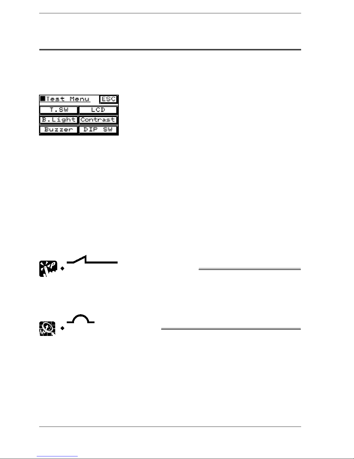
GT01 Configuration Settings
GT series
57
5.3 Entering Configuration Settings from the GT10 Main Unit
5.3.6 Test Mode: “Self-Diagnosis”
Touching the [Test] key on the initial screen of the system menu displays the
self-diagnosis screen. This is used to run a hardware check of the memory, buzzers,
and other elements of the GT01.
Test mode screen
Procedure for bringing up the screen
[Initial screen]
↓
[Test] key
Touch SW
This runs an operation check of the touch switches.
B. Light
The color of the backlight changes at one-second intervals (in sequence from green
a red a green a orange).
Buzzer
This runs an operation check of the buzzer.
LCD
This displays a pattern and runs an operation check of the display.
Contrast
Touch the [+] and [-] keys to check changes in the contrast.
Learning the shortcut keys saves time!
[RETURN]To complete the settings and return to the previous screen,
touch the [ESC] key.
Explanation of this function
•
Test mode (self-diagnosis) screen
On the test mode screen, the item name of the item that was just
tested is highlighted.
(The dots are cleared when the screen is returned to the initial screen
of the system menu.)
Page 78
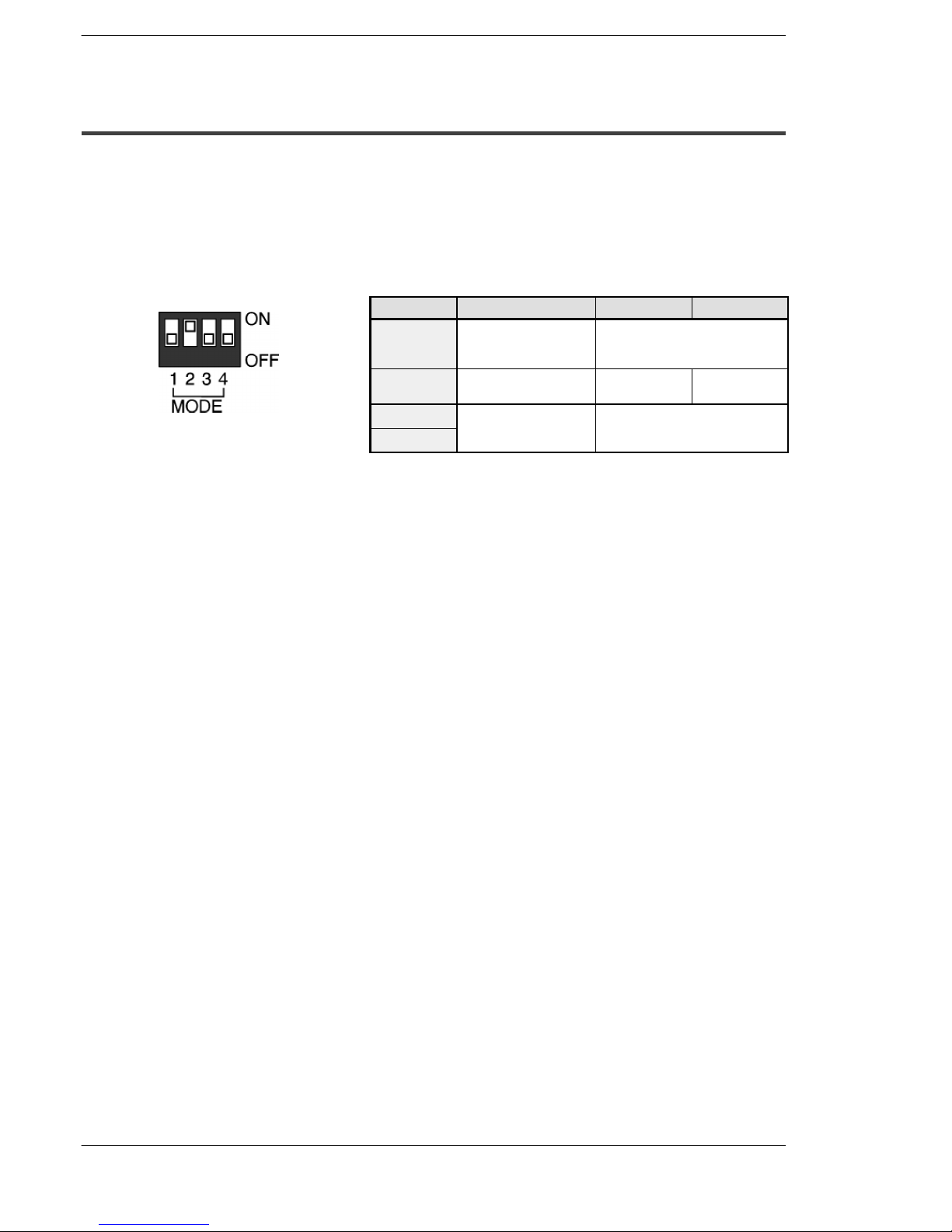
GT series
GT01 Configuration Settings
58
5.3 Entering Configuration Settings from the GT10 Main Unit
5.3.7 Inhibiting the System Menu Display
Inorder toprevent unauthorizedpersonsfrom beingable to change GT01 configuration
settings, the GT01 is set up so that DIP switches can be used to make it impossible to
display the system menu.
Switch no. Function OFF ON
1
Usage inhibited Should always be in the
“OFF” position when unit is
used.
2
Inhibitssystemmenu
shift
Shift possible Shift inhibited
3
Usage inhibited Should always be in the
“
”
4
“OFF”
position when unitis
used.
Operation mode setting switches
If the second operation mode setting switch is
turned on, as shown at the left, access to the
system menu is denied.
Page 79

Chapter 6
How the Various Functions Are Used
Page 80

GT seriesHow the Various Functions Are Used
60
Page 81
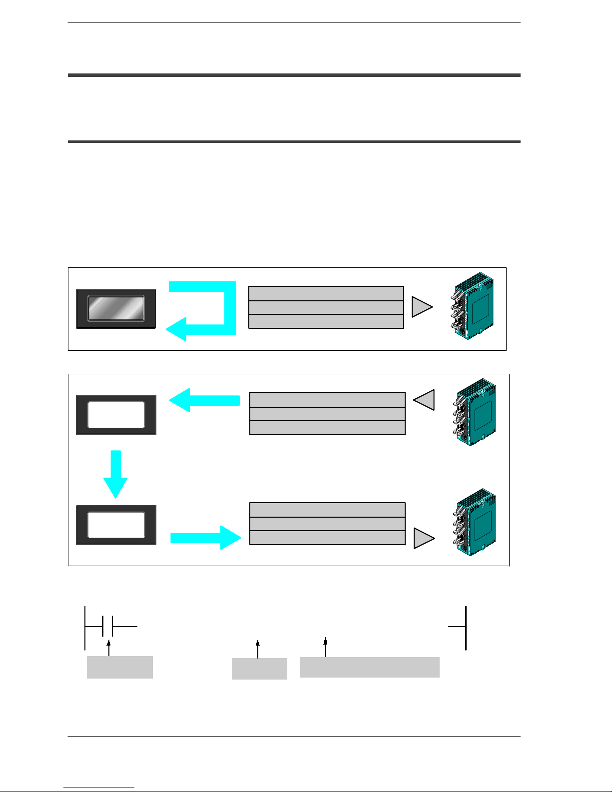
How the Various Functions Are UsedGT series
61
6.1 Switching Screens
6.1 Switching Screens
There are three ways to switch screens registered in the GT main unit.
6.1.1 Switching the Screen from the PLC
GT main unit screens can be switched from the PLC ladder program, by writing the
number of the screen to be displayed in hexadecimal format to the initial word of the
word device in the basic communication area.
At the same time that the screen is switched, the GT main unit writes the number of the
screen to which the display was switched in the first to third words of the basic
communication area, in hexadecimal format.
How communication is carried out between the GT main unit and PLC (screen
switching)
GT main unit
PLC
Basic communication area / word device
First word (specifies screen no. from PLC)
Second word (usage prohibited area)
Third word (no. of screen currently displayed)
Internal PLC device
Ongoing
communication
How screens are switched
GT main unit
PLC
GT main unit
PLC
Screen No. 1
Screen No. 2
When Screen No. 2
is specified by the
PLC
the screen
switches to
No. 2
and the PLC is notified that the screen
has been switched.
Basic communication area / word device
First word, HEX 2
Second word (usage prohibited area)
Third word, HEX 1
Basic communication area / word device
First word, HEX 2
Second word (usage prohibited area)
Third word, HEX 2
Example of ladder program
Basic screen display program
X0
[F0MV, H2, DT0]
No. of screen
displayed
Address of first word in basic
communication area / word device
Condition that
displays screen
When the screen is switched as a means of triggering switch output from the display
unit, the destination for the switch output should be specified in the condition that
displays the screen, indicated in the sample program above.
Page 82
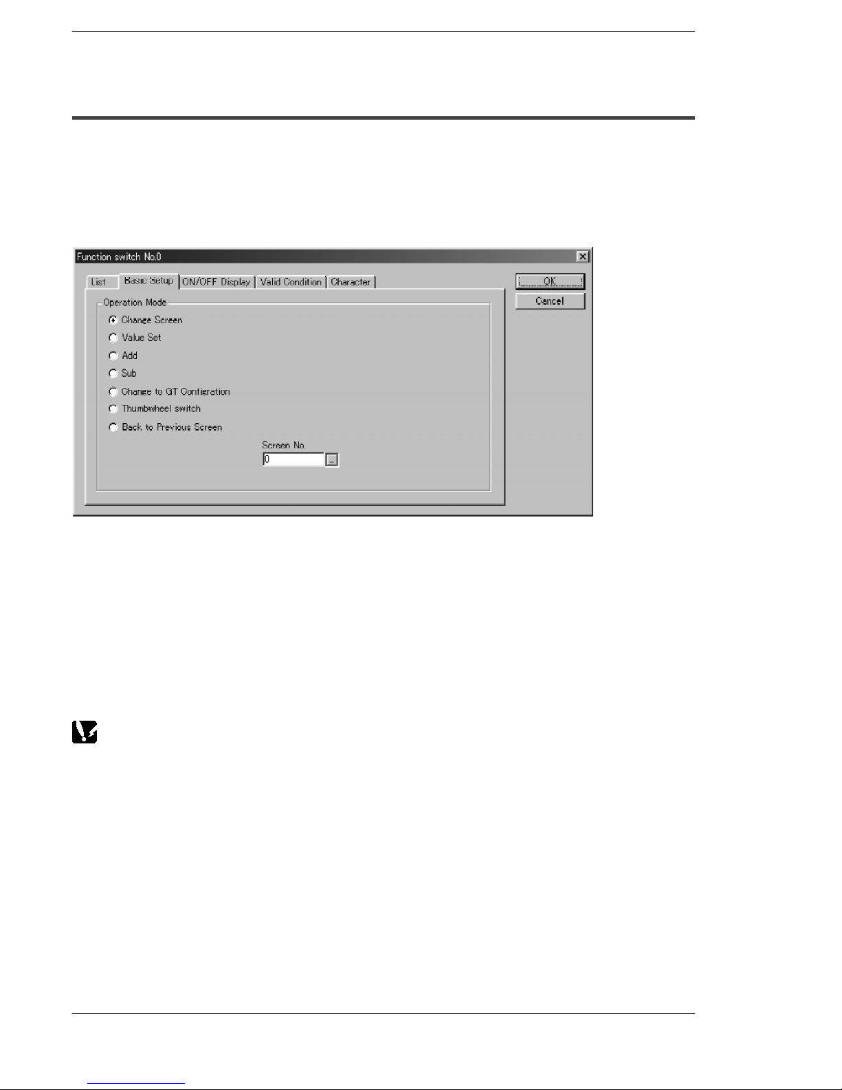
GT series
How the Various Functions Are Used
62
6.1 Switching Screens
6.1.2 Switching the Screen with the GT Main Unit
Using the function switch unit
GTWINhas“function switching parts” (FSW0,FSW1,FSW2)intheparts library that can
be used to switch screens on the GT main unit. These parts should be arranged on the
base screen and assigned the attributes indicated below.
Function switching parts: Attribute editing dialog box
Double-clicking on the parts arranged on the base screen, or selecting a switch part,
and clicking on the “Parts (T)” menu and then the “Edit Attribute” sub-menu displays
the dialog box shown above.
(1) Using the “Change Screen” operation mode
Select the “Change Screen” operation mode and specify the number of the screen to
be changed. Then press the switch part to switch the screen to the specified screen.
To return to thescreen displayedjust prior to the currently displayed screen,the “Return
to Previous Screen” operation mode can be used.
In this case, the value of the third word in the basic communication area / word
device(the number ofthe currentlydisplayed screen)changes to that of the new screen
number, but please be aware that the contents of the first word (the screen number
specified by the PLC) do not change. For detailed information, see page 65.
Page 83

How the Various Functions Are Used
GT series
63
6.1 Switching Screens
(2) Using the “Value Set” operation mode
Select the “Value Set” operation mode and enter the following settings:
- Data format: Specify 1 word
- Output destination: Specify to first word of basic communication area / word device
- Value: Number of screen to be changed to (hexadecimal specification)
Each time the GT main unit switch part is pressed, the screen number is forcibly written
bythe GTmain unitto the first word of the basic communicationarea /word device, and
the screen is switched.
If using this method, the values for both the first word of the basic communication
area / word device (the screen number specified by the PLC) and the third word (the
number of the currently displayed screen) are changed.
Page 84
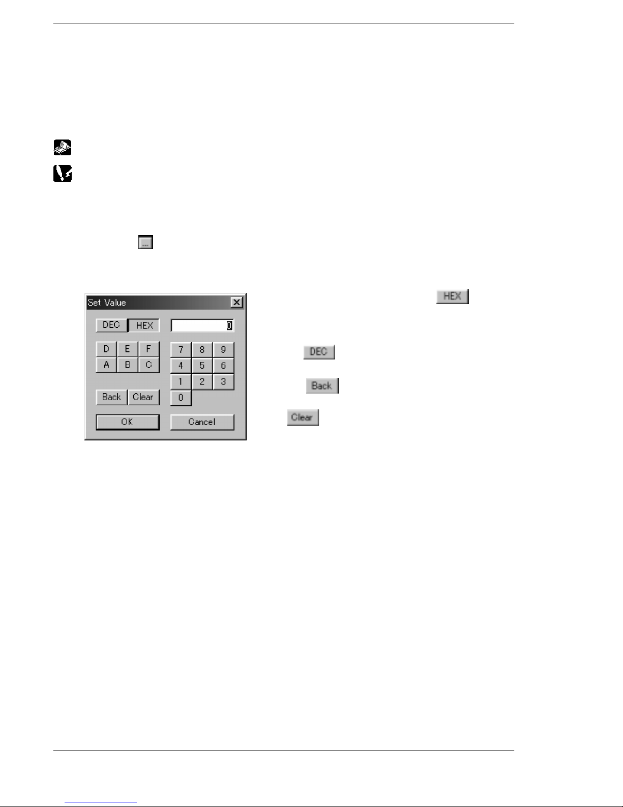
GT series
How the Various Functions Are Used
64
6.1 Switching Screens
Using the auto-paging function
TheGT main unithas an “Auto-paging” functionthat automatically switches the screen
to a specified screen number when a certain period of time has elapsed. This function
can be used to switch screens automatically.
For information on setting the auto-paging function, please see page 47 (GT01).
If using this function, please be aware that the value of the third word in the basic
communication area / word device (the number of the currently displayed screen)
changesto that of the new screen number, but the contents of the first word (the screen
number specified by the PLC) do not change. For detailed information, see page 65.
Clicking on the
button displays the value setting dialog box shown below. Specify
the number of the screen to which the display is to be changed.
Value Set dialog box
If the value is entered with the
button pressed as shown at the left, a
hexadecimal screen number is specified, and if the value is entered with
the button pressed, a decimal
value is entered.
The button acts as a backspace
key when entering an address, and the
button functions as a Clear key.
Page 85
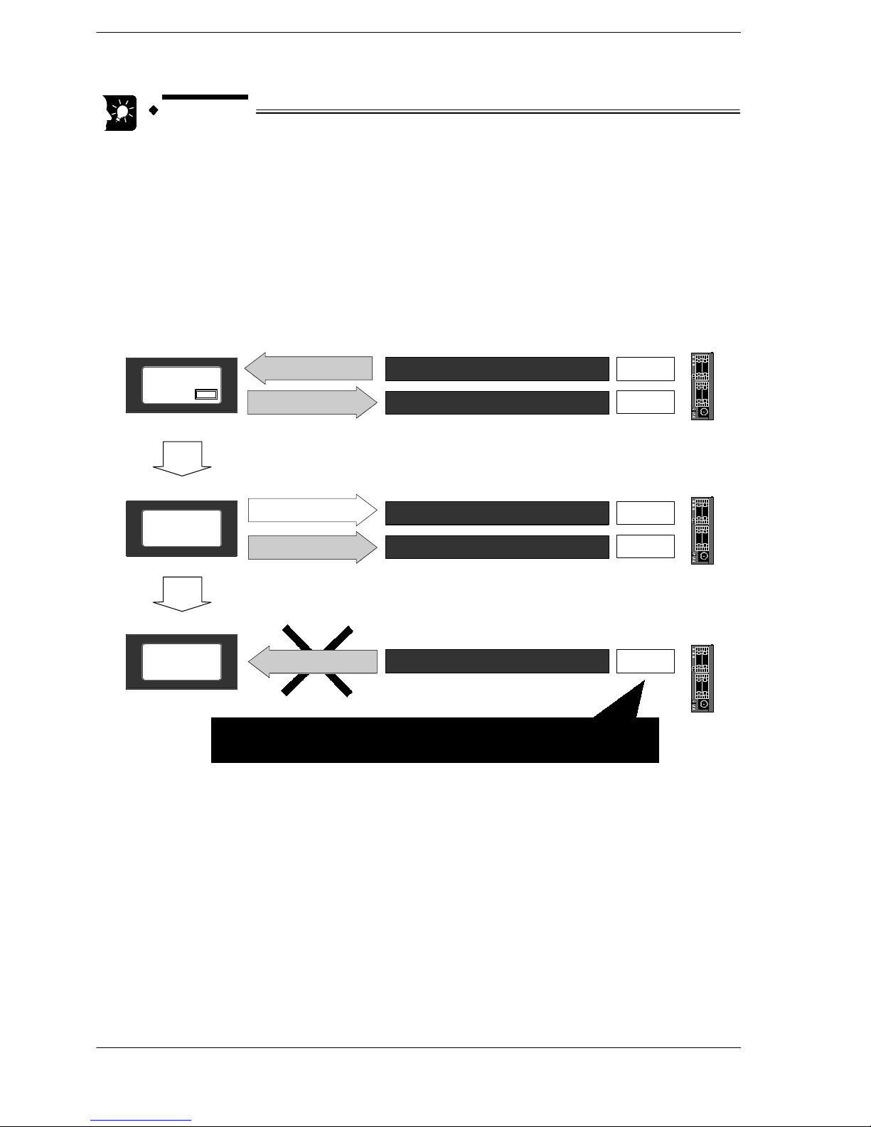
How the Various Functions Are Used
GT series
65
6.1 Switching Screens
Key points
•
If the screen does not change as expected
If the screen is changed from the PLC, and the GT main unit function
switch parts are also used to change the screen (Change Screen
operation mode), a case sometimes occurs in which the screen does
not change, even though an instruction to change the screen has
been issued by the PLC.
Example: Screen No. 1 is displayed in keeping with the instruction from the PLC, and
the screen is changed to Screen No. 2 using the function switch parts.
1
1
1
2
1
Screen No. 1
Currently display
screen number changes
Contents of basic communication area / word device
First word (screen no. instruction from PLC)
Third word (currently displayed screen no.)
Screen is switched in response to function switch parts (Change Screen operation mode)
Screen No. 2
Change is not reflected
Currently displayed
screen no. is changed
First word (screen no. instruction from PLC)
Third word (currently displayed screen no.)
Screen changing instruction from PLC
Screen No. 2
Screen changing
instruction
First word (screen no. instruction from PLC)
In this state, “1” is already written for the first word, so if an instruction is sent from the
PLC to the first word to display Screen No. 1, it duplicates what is already written, and the
screen will not be switched.
Screen switching
instruction
Page 86

GT series
How the Various Functions Are Used
66
6.1 Switching Screens
This problem can be solved in the following manner:
•
Use the “forced-display flag” in the basic communication area/bit
device.
1) At the same time that the PLC issues an instruction to change the
screen again to Screen No. 1, or shortly after that point, the
forced-display flag in the first word/Bit E of the basic communication
area/bit device is turned on, using the bit as a PLC bit operation
instruction.
2) When the forced-display flag begins to go on, the screen
corresponding to the number written to the first word of the basic
communication area/word device, meaning Screen No. 1, is forcibly
displayed at the point that step 1 takes place. (This is carried out only
at the rise of the forced-display flag).
3) After the screen has been switched, the forced-display flag should
be turned off.
•
Set the operation mode of the function switch parts to “Value Set”.
When the screen is switched using the function switch parts, as
shown in the illustration above, the operation mode of the function
switch parts is set to “Value Set” in order to switch the screen. (For
detailed information, see page 62.)
Using the “Value Set” mode changes the contents of the first word in
the basic communication area/word device (the screen number
specified by the PLC) and the third word (the number of the currently
displayed screen) to that of the new screen number, and thus avoids
the kind of case described above.
Page 87
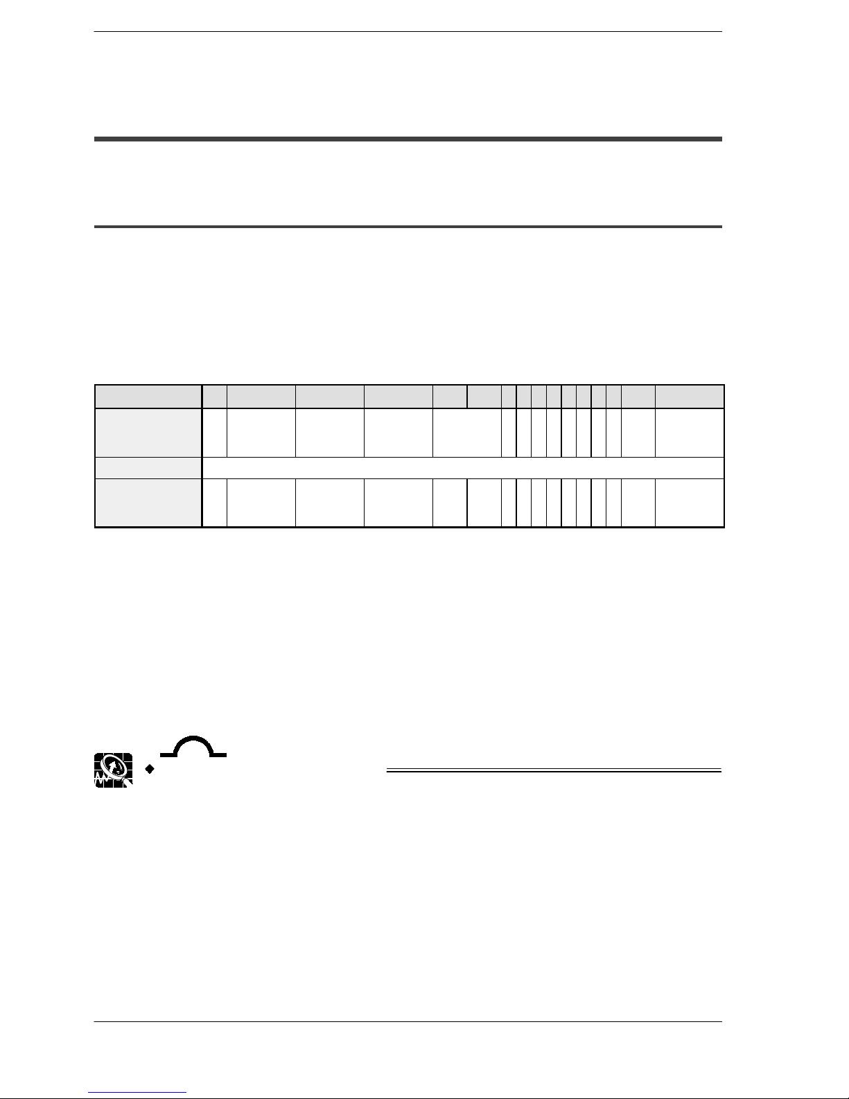
How the Various Functions Are Used
GT series
67
6.2 Basic Communication Area to PLC and Bit Device Functions (GT01)
6.2 Basic Communication Area to PLC and Bit Device
Functions (GT01)
6.2.1 Bit Device Functions
In order for communication to be carried out between the GT01 and PLC, an internal
device area like that shown below is provided in the PLC. This basic communication
area contains two types of devices: word devices, which are used to handle screen
numbersand other data,and bit devices,which are usedfor bit information. The various
bits of the bit devices are turned on and off from the PLC, and can be used to control
various GT01 operations.
Bit devices
Word position F E D C B A 9 8 7 6 5 4 3 2 1 0
N+0
BZ Forced-
display
flag
Backlight
Validflag
Backlight
Flashing
Backlight
Color
N+1
Usage prohibited
N+2
Data Input
In Progress flag
Explanation of system areas
BZ -- - This turns on the buzzer.
Forced-Display flag -- - At the rise when the bit is turned on, the screen specified by
the PLC is forcibly displayed. (This is executed only when at the rise of the bit.)
Backlight Valid flag - - - When the bit is turned on, the backlight flashing/backlight
color control becomes effective.
Backlight Flashing - - - 0: Lighted (normal), 1: Flashing
Backlight Color - - - 00: Off, 01: Green, 10: Red, 11: Orange
Data Input In Progress flag -- - This is 1 while data is being input, and 0 when data
input has been completed.
Explanation of this function
DT0 to DT2 and WR0 to WR2 are set as the default values for the basic
communication area.
For information on the contents of all areas of the basic communication
area, please see page 26.
Page 88
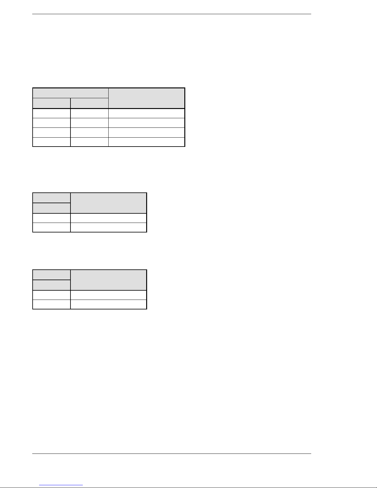
GT series
How the Various Functions Are Used
68
6.2 Basic Communication Area to PLC and Bit Device Functions (GT01)
Changing the backlight color
Bits A and B of the first word of the bit device are used to change the backlight
color.The color of the backlight can be changed by turning these bits on and off.
To make these settings valid, however, Bit D (Backlight Valid flag) must always
be turned on at the same time.
Bit status Backlight color
B A
OFF OFF
Off
OFF ON
Green
ON OFF
Red
ON ON
Orange
Using a flashing backlight
Bit C of the first word of the bit device is used to make the backlight flash. The backlight
status can bechanged byturning thisbit onand off. Tomake this setting valid, however,
Bit D (Backlight Valid flag) must always be turned on at the same time.
Bit status Backlight status
C
OFF
Lighted
ON
Flashing
Making the buzzer sound
Bit F of the first word of the bit device is used to make the buzzer sound. The buzzer
status can be changed by turning this bit on and off.
Bit status Buzzer status
F
OFF
Stopped
ON
Buzzer output
Data Input in Progress flag
With the GT01, while data is beinginput from the screen keyboardpart, Bit 0of the third
word of the bit device is on.
Applications should be set up so that, whenthis bit is on, the screen cannot be changed
from the PLC.
Page 89

Chapter 7
Servicing and Maintenance
Page 90

GT seriesServicing and Maintenance
70
Page 91
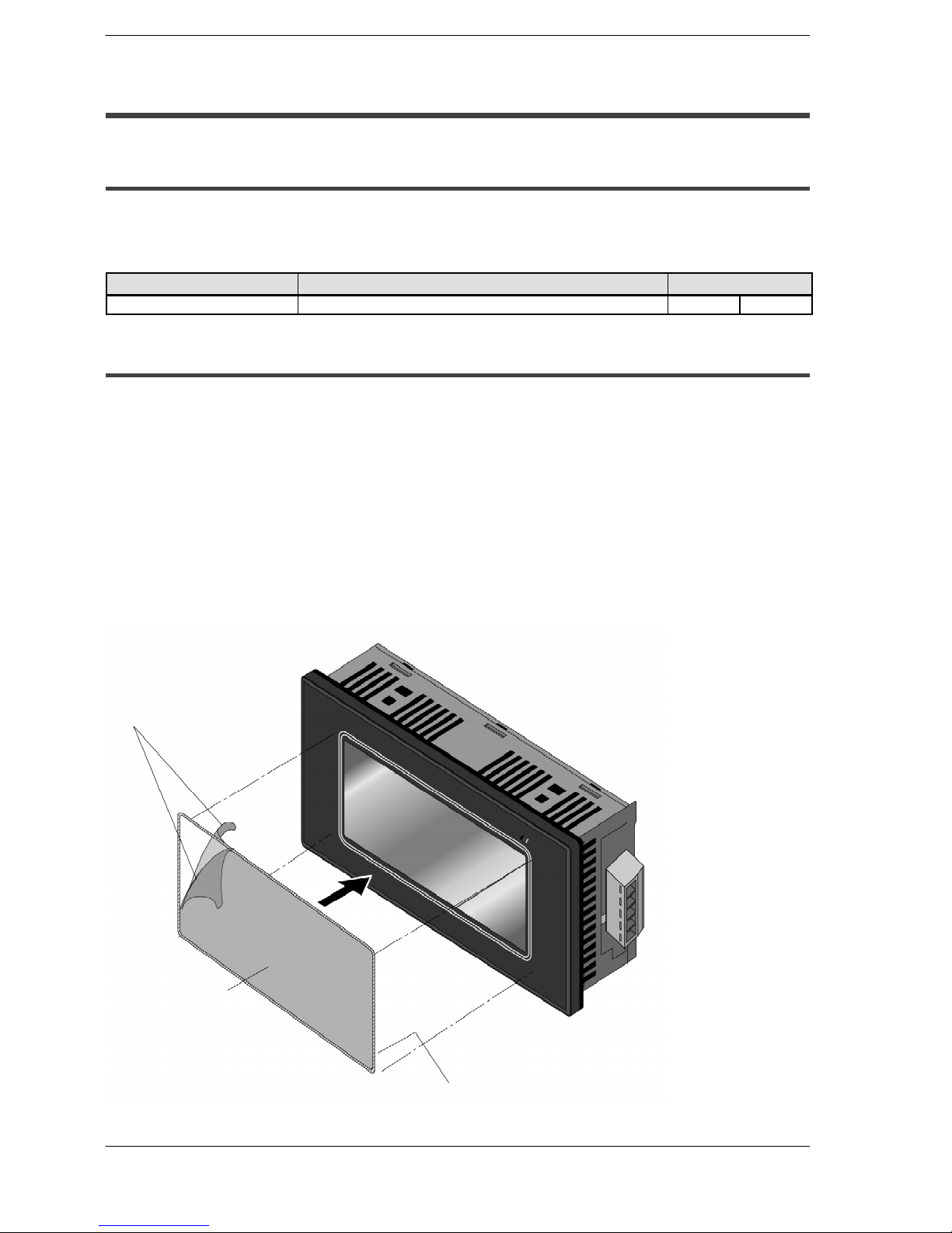
Servicing and MaintenanceGT series
71
8.3 Replacing the Front Panel Protective Sheet
7.1 Replacing the Front Panel Protective Sheet
7.1.1 About the Front Panel Protective Sheet
Protective sheets are available in order to protect the touch panel surface and to keep
it clean. Please use the following separately-sold protective sheets if there is a
possibility that the touch panel surface will become dirty.
Product name Contents Product number
Front panel protective sheet Front panel protective sheets for replacement (set of 10) For GT01 AIGT080
7.1.2 Replacing the Front Panel Protective Sheet
Follow the steps below to replace the sheet:
1. Remove the attached front panel protective sheet.
First, peel off the front panel protective sheet already attached to the GT main unit,
starting from the knob is.
2. Peel off the seal from the provided protector sheet and attach it to the unit.
Take out one of the replacement front panel protective sheets and peel off the seal with
the shiny side. When attaching the sheet, align the adhesive edges with the front of the
GT main unit.
3.Finishby peeling off thethinfilmattachedtothetopofthefront panelprotective
sheet.
Peel off the front film.
Front
Adhesive face (attached seal)
Page 92
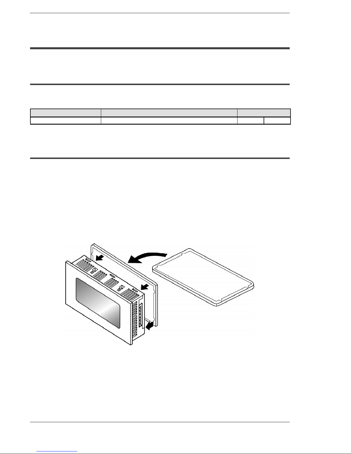
GT series
Servicing and Maintenance
72
8.4 Replacing the Waterproof Packing
7.2 Replacing the Waterproof Packing
7.2.1 About the Waterproof Packing
Ifthepanel is being detachedfromtheGT main unitandthenreattached, the waterproof
packingshouldbereplaced, in order toassurethat the panelremainswaterproof (IP65).
Product name Contents Product number
Waterproof packing Waterproof packings for replacement (set of 10) For GT01 AIGT081
7.2.2 Replacing the Waterproof Packing
Follow the steps below to replace the packing:
1. Remove the currently attached waterproof packing.
Remove the attached waterproof packing from the GT main unit.
2. Attach the provided waterproof packing.
Take out one of the replacement waterproof packing pieces and attach the outer edge
as shown in the illustration (do not use the inner edge).
When doing this, fasten it to the front frame, being sure not to twist the waterproof
packing.
Page 93

Chapter 8
Troubleshooting
Page 94

GT seriesTroubleshooting
74
Page 95
TroubleshootingGT series
75
8.1 What to Do If Something Unusual Occurs (GT01)
8.1 What to Do If Something Unusual Occurs (GT01)
Problem Cause Solution Related
Screen is
blank
1)Power is not on.
2)(When only lamp and message parts
are configured to the base screen)
Valueof substitute reference device
value does not exist in substitute data.
1)Supply 5V DC power to unit.
2)Check the address of the substitute
reference device and the device values on the PLC side.
P.16
GTWIN HELP
Error code
[ER**]
appears at
the top right
of the screen
An error has occurred in communication
between the GT01 and an external device (e.g. PLC).
[Troubleshooting error codes] are listed
on P.78. Refer to this section for details.
P.78
Screen
displays
[No Screen
data]
There is no base screen data in the
GT01. (Appears even when GT01 configuration data exists.)
Transfer base screen data from GTWIN. GTWIN HELP
Screen
displays
[Screen No.
Error]
1)Screen settings from the PLC, the
GT01’s switch part or the auto-paging
indicate an unregistered screen number.
2)When bringingup thekeyboard screen
duringdata input, anunregistered keyboard screen number was specified.
3)GT01 configurationdata andkeyboard
screen data exist in the GT01, but
there is no base screen data.
1)Create and register screen content or
specify the correct screen number.
2)Create and register keyboard screen
or specify the correct keyboard number.
3)Transfer base screen data from
GTWIN.
P.64
GTWIN HELP
GTWIN HELP
Screen
displays
[Memory is
Full]
The total capacity of transferred base
screen data exceeds the 384kbyte capacity of the GT01.
Delete part of the base screen data so
that the total capacity doesn’t exceed
384kbyte. Data capacity can be checked
by going to [View (V)] → [Memory Usage
Conditions] on GTWIN menu bar.
GTWIN HELP
An
unspecified
screen
appeared /
there is
troublewhen
switching
screens
1)The screen specification in the PLC
screen setting, the GT01 switch part
or the auto-paging is wrong.
2)The startup screen is specified in the
GT01 configuration settings (GTWIN).
3)An erroneous device or value is specified in the first word of the basic communication area word device.
1)Specify the correct screen number.
2)Check the start-up screen setting for
the GT01 configuration settings in
GTWIN. Delete unnecessary settings
and re-transfer configuration data.
3)Check the device content specified on
the PLC side in the first word of the
basic communication area. (Do not
use the basic communication area
with ladder programs.)
P.64
P.46
P.24 to P.26
Screen
doesn’t
switch
1)No screen number has been written to
the screen setting area (the first word
in the basic communication area word
device) from the PLC.
2)The screen number to which you are
attempting to switch has already been
written fromthe PLC to the screen setting area (the first word in the basic
communication area word device).
1)Specify correct screen number.
2)Refer to P.65 [If the screen does not
change as expected]. (Do not use the
basic communication area with ladder
programs.)
P.64
P.65
Page 96
GT series
Troubleshooting
76
8.1 What to Do If Something Unusual Occurs (GT01)
Problem Cause Solution Related
Screen is
dim
1)The power voltage may be low.
2)The contrast is set too low.
3)The backlight is off due to the [Backlight Auto-off] setting in the [Setup] of
the GT01 configuration settings in
GTWIN.
1)Supply 5V DC 0.2 A.
2)Bring up the system menu and adjust
the contrast.
3)Touchingany area of the screen lights
that area. If a switch part is set on the
touched area, the area will not light
evenif touched. To change thesetting,
change the content of the backlight
auto-off settings.
P.16
P.55
P.51
Backlight
goes off too
quickly
Thebacklight auto-offtimer settingis too
short.
Change the backlight auto-off timer setting.
P.51
Date / time
display is
incorrect
1)The PLC’s internal calendar timer
used as a reference is incorrect.
1)Adjust by rewriting the value in the
PLC’s internal calendar timer.
All PLC
manuals
Touch panel
doesn’t work
1)Valid conditions have been set for the
switch part, but those conditions have
not been met. (Applies only to custom
parts.)
1)Check that the device status conditions on the PLC side are valid.
GTWIN HELP
No operating
sounds are
heard when
the touch
panel is
pressed.
1)The [Switch Sounds] setting under
[Options] in the switch part attributes
is set to [Disabled].
2)The [Touch Sounds] setting under
[Setup] in the GT01 configuration settings in GTWIN is set to [Disabled].
1)Change the setting to [Enabled].
2)Change the setting to [Enabled].
GTWIN HELP
Page 97
Troubleshooting
GT series
77
8.1 What to Do If Something Unusual Occurs (GT01)
Problem Cause Solution Related
Buzzer
sounds
continuously
Bit F of the first word in the basic communication area bit device is set to ON.
Set the F bit to OFF on the PLC side.
(Do not use the basic communication
area with ladder programs.)
P.67 to P.68
Backlight
color
changes /
flashes
Bits A and B, and Bit D, of the first word
(backlight color setting) in the basic communication area bit device are set to ON.
Or, Bits C and D (backlight flashing setting) are set to ON.
Perform correct bit operations on the
PLC side. (Do not use the basic communication area with ladder programs.)
P.67 to P.68
Cannot
transfer data
from GTWIN
1)The screen transfer cable is not connected.
2)The PC and GT01 COM. port are connected.
1)Confirm that the screen transfer cable
is correctly and firmly connected.
2)Connect to TOOL port with screen
transfer cable.
GTWIN HELP
* Screen is
blank (power
supply and
substitution
settings
above are
correct)
*An
incorrect
screen is
displayed
(error codes
and
erroneous
date and
time items
noted above
do not
apply)
* Switch
doesn’t work
(grid and
validity
settings
noted above
are correct)
An error has occurred in the GT01 system.
1)After confirming the safety of the device, etc., turn off the power supply
and then turn it on again. The GT01
CPU will be reset.
2)If 1) produces no change, bring up the
system menu and initialize the
memory (F-ROM), then transfer data
again from GTWIN to the GT01.
CAUTION:
When doing this, all base screen data,
GT01 setting data, keyboard screen
data, and bitmap data will be lost. Before doing this, make sure all data has
been backed up.
3)If 2) produces no change, set the operatingmode setting switches 2, 3 and
4 on the rear of the GT01 to ON and
reset the power supply.
CAUTION:
Whendoing this, all ofthe contents will
revert to those in effect at the time of
shipping, and all of the GT01 memory
contents will be cleared. Before doing
this, make sure all data has been
backed up.
P.56
Page 98
GT series
Troubleshooting
78
8.2 Error Codes and How to Handle Them
8.2 Error Codes and How to Handle Them
8.2.1 About Error Codes
When an error occurs in the GT series, an error code displays at the top right of the
screen.There aretwo typesof error codes, GT series error codes andPLC error codes.
ER XX
Error code display
8.2.2 GT Series Error Codes
When connected to a FP series PLC
The following three types of error codes are displayed when there is an error in the GT
main unit:
Code no. Content Cause and solution
FF
Time up error
Noresponse from thePLC.
1)The PLC connection cable is disconnected. Check the connection
cable to make sure it is connected.
2)There is a temporary error due to noise, etc. Re-supply power to the
PLC and GT main unit.
21
Data error
A data error occurred during communication.
1)An error exists in the communication condition settings. Check the
PLC and GT main unit communication speed and transfer format.
2)There is a temporary error due to noise, etc. Re-supply power to the
PLC and GT main unit.
22
Overrun error
The GT main unit cannot
receive data.
The reception buffer in the GT main unit is overflowing.
There could be an error in the PLC.
Re-supply power to the PLC and GT main unit.
Page 99
Troubleshooting
GT series
79
8.2 Error Codes and How to Handle Them
8.2.3 PLC Error Codes
Errorcodes which aresent from thePLC are listedin the tablebelow.For details,please
refer to the separate [Computer Communication Unit Introductory Manual].
Code no. Content Cause and solution
21
Data error
A data error occurred during communication.
1)There is an error in the communication condition settings. Check the PLC and GT01 communication speed and transfer format.
2)There is a temporary error due to noise, etc.
Re-supply power to the PLC and GT01.
22
Overrun error
The PLC isn’t receiving data.
The CPU unit’s reception buffer is overflowing.
There could be an error in the PLC.
Re-supply power to the PLC and GT01.
40
BCC error
A data error occurred during communication.
1)There is a temporary error due to noise, etc.
Re-supply power to the PLC and GT01.
2)There is an error in the CPU unit. Re-supply
power to the PLC and GT01.
41
Format error
The PLC has been sent a command that doesn’t
match the protocol.
1)There is a temporary error due to noise, etc.
Re-supply power to the PLC and GT01.
2)There is an error in the CPU unit. Re-supply
power to the PLC and GT01.
42
NOT support error
The GT01 has sent a non-supported command
to the PLC.
1)There is a temporary error due to noise, etc.
Re-supply power to the PLC and GT01.
2)There is an error in the CPU unit. Re-supply
power to the PLC and GT01.
53
BUSY error
The PLC is currently processing another command.
A large amount of data is being communicated
with another RS232C port on the PLC.
Wait until the error is gone.
61
Data run error
There is an error in the register or relay number.
A register or relay number which doesn’t exist in
the PLC was specified during screen creation
using GTWIN.
Correct the output device being used with the
part, or the transfer of clock data to an external
device.
Page 100
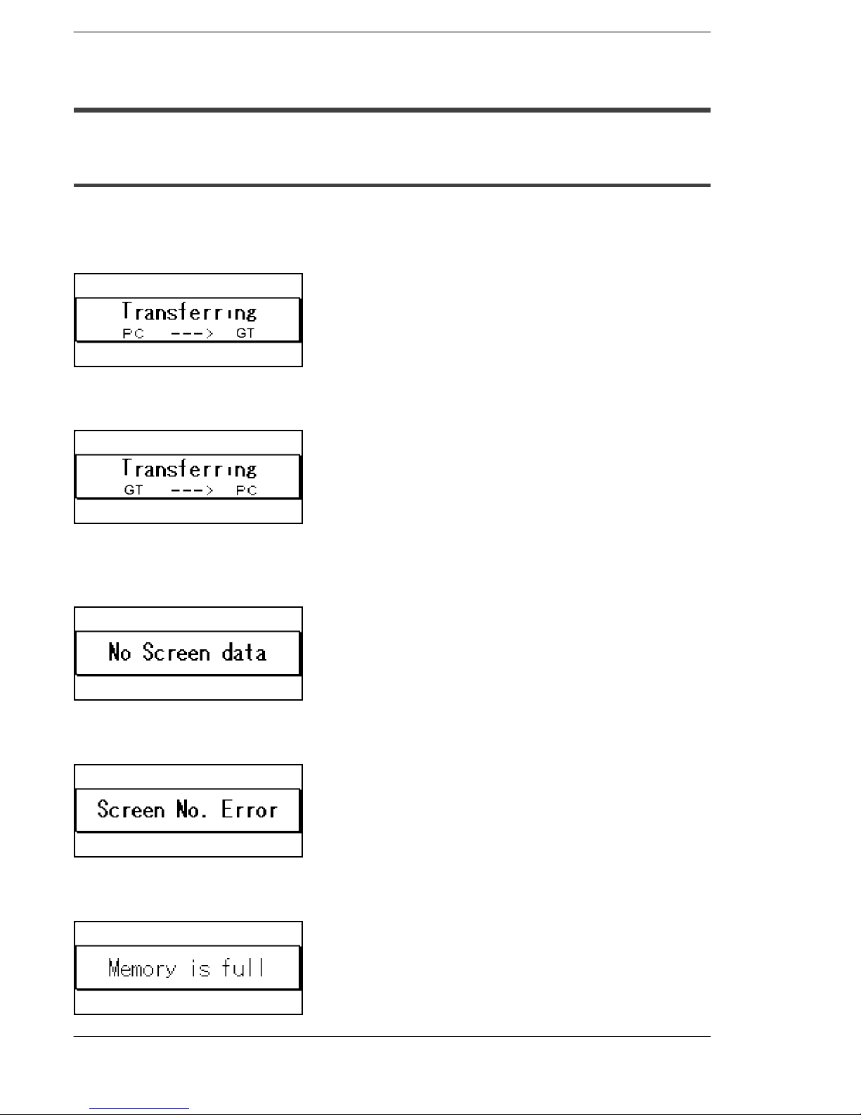
GT series
Troubleshooting
80
8.3 Table of Screen Messages
8.3 Table of Screen Messages
8.3.1 Table of GT01 Screen Messages
In addition to screen data, the GT01 also displays the following messages.
When transferring data from personal computer to a GT01
This is displayed when data is being transferred from the computer to the GT01.
When transferring data from GT01 to a personal computer
This is displayed when data is being transferred from the GT01 to the computer.
When there is no base screen data
This is displayed when there is no base screen data. (It is displayed even if the
configuration data has been sent.)
When the specified screen does not exist
This is displayed in cases such as when there is no data for a specified screen number.
When the screen memory is full
This is displayed if the internal user memory (F-ROM) is full.
 Loading...