

Page 1
PROGRAMMABLE CONTROLLER
User’s Manual
[Applicable PLC]
FPΣControl units
FPG-C32T
•
FPG-C32T2
•
FPG-C24R2
•
FP
Σ
This manual was created using Adobe Acrobat.
Adobe, the Adobe logo, and Acrobat are trademarks
of Adobe Systems Incorporated.
http://www.naisplc.com
Page 2

Table of Contents
FPΣ
i
Table of Contents
Before You Start viii....................................................
Programming Tool Restrictions xi........................................
Compatibility with the FP0 xii............................................
Chapter 1 Functions and Restrictions of the Unit
1.1 Features and Functions of the Unit 1 - 3...............................
1.2 Unit Types 1 - 6....................................................
1.2.1 FPΣ Control Unit 1 - 6.......................................
1.2.2 FPΣ Expansion Unit 1 - 6.....................................
1.2.3 Units for FP0 and FPΣ 1 - 6..................................
1.2.4 Communication Cassette 1 - 6................................
1.3 Restrictions on Unit Combinations 1 - 7................................
1.3.1 Restrictions on the Number of Expansion Units
(for FP0 expansion unit) 1
-
7.................................
1.3.2 Restrictions on the Number of Units for Expansion
(for FPΣ expansion unit) 1-8.................................
1.4 Programming Tools 1 - 9.............................................
1.4.1 Tools Needed for Programming 1 - 9..........................
1.4.2 Software Environment and Suitable Cable 1 - 9.................
Chapter 2 Specifications and Functions of Control Unit
2.1 Parts and Functions 2 - 3............................................
2.1.1 Parts and Functions 2 - 3....................................
2.1.2 Tool Port Specification 2 - 6..................................
2.1.3 Communication Cassette 2 - 6................................
2.2 Input and Output Specifications 2 - 7..................................
2.2.1 Input Specifications 2 - 7.....................................
2.2.2 Output Specifications 2 - 9...................................
2.3 Terminal Layout Diagram 2 - 12........................................
2.3.1 Control Unit (for C32T and C32T2) 2 - 12.......................
2.3.2 Control Unit (for C24R2) 2 - 12.................................
Chapter 3 Expansion
3.1 Type of Expansion Unit 3 - 3.........................................
Page 3

Table of Contents FPΣ
ii
3.2 Expansion Method of Units for FP0 and FPΣ 3 - 4.......................
3.3 Expansion Method of FPΣ Expansion Unit 3 - 5.........................
3.4 Specifications of FPΣ Expansion Unit 3 - 6.............................
3.4.1 FPΣ Expansion I/O Unit 3 - 6.................................
Chapter 4 I/O Allocation
4.1 I/O Allocation 4 - 3..................................................
4.1.1 I/O Number of FPΣ Control Unit 4 - 3..........................
4.1.2 I/O Number of FPΣ Expansion Unit (for left side expansion) 4 - 4..
4.1.3 I/O Number of FP0 Expansion Unit (for right side expansion) 4 - 5.
4.1.4 I/O Number of FP0 Analog I/O Unit (for right side expansion) 4 - 5.
4.1.5 I/O Number of FP0 A/D Conversion Unit
(for right side expansion) 4 - 5................................
4.1.6 I/O Number of FP0 I/O Link Unit (for right side expansion) 4 - 6...
Chapter 5 Installation and Wiring
5.1 Installation 5 - 3....................................................
5.1.1 Installation Environment and Space 5 - 3.......................
5.1.2 Installation and Removal 5 - 6................................
5.2 Wiring of Power Supply 5 - 9.........................................
5.2.1 Wiring of Power Supply 5 - 9.................................
5.2.2 Grounding 5 - 11.............................................
5.3 Wiring of Input and Output 5 - 12......................................
5.3.1 Input Wiring 5 - 12...........................................
5.3.2 Output Wiring 5 - 15..........................................
5.3.3 Precautions Regarding Input and Output Wirings 5 - 16...........
5.4 Wiring of MIL Connector Type 5 - 17...................................
5.5 Wiring of Terminal Block Type 5 - 20....................................
5.6 Safety Measures 5 - 22...............................................
5.6.1 Safety Measures 5 - 22.......................................
5.6.2 Momentary Power Failures 5 - 23..............................
5.6.3 Protection of Power Supply and Output Sections 5 - 23...........
5.7 Backup Battery 5 - 24................................................
5.7.1 Installation of Backup Battery 5 - 24............................
5.7.2 System Register Setting 5 - 25.................................
5.7.3 Lifetime of Backup Battery 5 - 26...............................
Page 4

Table of Contents
FPΣ
iii
Chapter 6 High-speed Counter and Pulse Output Functions
6.1 Overview of Each Functions 6 - 3.....................................
6.1.1 Three Functions that Use Built-in High-speed Counter 6 - 3......
6.1.2 Performance of Built-in High-speed Counter 6 - 4...............
6.2 Function Specifications and Restricted Items 6 - 5......................
6.2.1 Table of Specifications 6 - 5..................................
6.2.2 Function being Used and Restrictions 6 - 7.....................
6.2.3 Booting Time 6 - 9..........................................
6.3 High-speed Counter Function 6 - 10...................................
6.3.1 Overview of High-speed Counter Function 6 - 10.................
6.3.2 Types of Input Modes 6 - 10...................................
6.3.3 Min. Input Pulse Width 6 - 12..................................
6.3.4 I/O Allocation 6 - 12..........................................
6.3.5 Instructions Used with High-speed Counter Function 6 - 13........
6.3.6 Sample Program 6 - 16.......................................
6.4 Pulse Output Function 6 - 20..........................................
6.4.1 Overview of Pulse Output Function 6 - 20.......................
6.4.2 T ypes of Pulse Output Method 6 - 21...........................
6.4.3 I/O Allocation 6 - 22..........................................
6.4.4 Control Mode 6 - 23..........................................
6.4.5 Instructions Used with Pulse Output Function 6 - 24..............
6.4.6 Sample Program for Positioning Control 6 - 43...................
6.5 PWM Output Function 6 - 56..........................................
6.5.1 Overview of PWM Output Function 6 - 56.......................
6.5.2 Instruction Used with PWM Output Function 6 - 56...............
Chapter 7 Communication Cassette
7.1 Communication Functions of FPΣ 7 - 3................................
7.1.1 Functions of Communication Cassette 7 - 3....................
7.2 Communication Cassette 7 - 6........................................
7.2.1 T ype of Communication Cassette 7 - 6.........................
7.2.2 Names and Principle Applications of the Ports 7 - 7..............
7.2.3 Communication Specifications of Communication Cassette 7 - 8..
7.3 Attachment of Communication Cassette 7 - 10...........................
7.3.1 Attachment Procedure 7 - 10..................................
Page 5

Table of Contents
FPΣ
iv
7.4 Wiring of Communication Cassette 7 - 11...............................
7.4.1 Wiring the Connector with the Communication Cassette 7 - 11.....
7.4.2 Tool for Tightening Communication Connector Terminal Block 7 - 12
7.4.3 Wiring Method 7 - 12.........................................
7.4.4 Cautions Regarding Wiring 7 - 12..............................
Chapter 8 Communication Function 1 Computer Link
8.1 Computer Link 8 - 3.................................................
8.1.1 Overview of Function 8 - 3...................................
8.1.2 Explanation of Operation when Using a Computer Link 8 - 4......
8.1.3 Format of Command and Response 8 - 5......................
8.1.4 Types of Commands that Can Be Used 8 - 8...................
8.1.5 Setting the Communication Parameters when
Using a Computer Link 8 - 10..........................................
8.1.6 Restriction 8 - 10.............................................
8.2 Connection Example with External Device 8 - 11.........................
8.2.1 Connection Example with External Device
(1:1 communication with computer) 8 - 11......................
8.2.2 Connection Example with External Device
(1:1 communication with programmable display “GT10/GT30”) 8 - 14
8.3 Computer Link (1:N communication) 8 - 18..............................
8.3.1 Overview of 1:N Communication 8 - 18.........................
8.3.2 Communication Cassette Used for 1:N Communication 8 - 18......
8.3.3 Settings of System Register and Unit No. 8 - 19..................
8.3.4 Connection with External Device 8 - 22.........................
Chapter 9 Communication Function 2 General-purpose
Serial Communication
9.1 General-purpose Serial Communication 9 - 3..........................
9.1.1 Overview of Function 9 - 3...................................
9.1.2 Program of General-purpose Serial Communication 9 - 5........
9.1.3 Communication Parameter Settings when Using
General-purpose Serial Communications 9
-
6..................
9.2 Overview of Communication with External Devices 9 - 8.................
9.2.1 Data Transmission to External Device 9 - 8.....................
9.2.2 Receiving Data from External Device 9 - 12......................
Page 6

Table of Contents
FPΣ
v
9.3 Connection Example with External Devices 9 - 16........................
9.3.1 Connection Example with External Device
(1:1 communication with Micro-Imagechecker) 9 - 16.............
9.3.2 Connection Example with External Device
(1:1 communication with FP series PLC) 9 - 22..................
9.4 Data Transmitted and Received with the FPΣ 9 - 29......................
9.5 1:N Communication 9 - 31............................................
9.5.1 Overview of 1:N Communication 9 - 31.........................
9.5.2 Communication Cassette Used with 1 : N Communication 9 - 31...
9.5.3 Setting of System Register 9 - 32..............................
9.6 Flag Operations When Using Serial Communication 9 - 33................
9.6.1 When “STX not exist” is Set for Start Code and “CR” is
Set for End Code 9 - 33.......................................
9.6.2 When “STX” is Set for Start Code and “ETX” is Set for
End Code 9 - 35.............................................
9.7 Changing the Communication Mode of COM. Port 9 - 37..................
Chapter 10 Communication Function 3 PLC Link Function
10.1 PLC Link 10 - 3......................................................
10.1.1 Overview of Function 10 - 3...................................
10.2 Communication Parameter Settings 10 - 5..............................
10.2.1 Setting of Communication Mode 10 - 5..........................
10.2.2 Setting of Unit No. 10 - 6......................................
10.2.3 Allocation of Link Relay and Link Register 10 - 10.................
10.2.4 Setting the Largest Station Number for a PLC Link 10 - 16..........
10.3 Monitoring When a PLC Link is Being Used 10 - 17........................
10.3.1 Monitoring Using Relays 10 - 17.................................
10.4 Connection Example of PLC Link 10 - 18.................................
10.4.1 Using a PLC Link with Three FPΣ Units 10 - 18....................
10.4.2 Sample Programs 10 - 21......................................
10.5 PLC Link Response Time 10 - 22.......................................
10.5.1 PLC Link Response Time 10 - 22................................
10.5.2 Shortening the Transmission Cycle Time When There are
Stations That Have not been Added to the Link 10
-
25.............
10.5.3 Error Detection Time for Transmission Assurance Relays 10 - 26....
Page 7

Table of Contents
FPΣ
vi
Chapter 11 Other Functions
11.1 Analog Potentiometer 11 - 3...........................................
11.1.1 Overview of Analog Potentiometer 11 - 3........................
11.1.2 Example Showing How the Analog Potentiometers are Used 11 - 3.
11.2 Clock/Calendar Function 11 - 4........................................
11.2.1 Area for Clock/Calendar Function 11 - 4.........................
11.2.2 Setting of Clock/Calendar Function 11 - 4.......................
11.2.3 Precautions Concerning Backup of Clock/Calendar Data 11 - 5....
11.2.4 Example Showing the Clock/Calendar being Used 11 - 6..........
Chapter 12 Self-Diagnostic and Troubleshooting
12.1 Self-Diagnostic Function 12 - 3........................................
12.1.1 LED Display for Status Condition 12 - 3.........................
12.1.2 Operation on Error 12 - 4......................................
12.2 Troubleshooting 12 - 5................................................
12.2.1 If the ERROR/ALARM LED Flashes 12 - 5.......................
12.2.2 If the ERROR/ALARM LED Lights 12 - 7........................
12.2.3 If None of the LEDs Light 12 - 7................................
12.2.4 If Outputting does not Occur as Desired 12 - 8...................
12.2.5 If a Protect Error Message Appears 12 - 10.......................
12.2.6 If the Program Mode does not Change to RUN 12 - 10.............
12.2.7 If a Transmission Error has Occurred 12 - 11.....................
Chapter 13 Specifications
13.1 Table of Specifications 13 - 3..........................................
13.1.1 General Specifications 13 - 3..................................
13.1.2 Performance Specifications 13 - 5..............................
13.2 I/O No. Allocation 13 - 10..............................................
13.3 Relays, Memory Areas and Constants 13 - 12............................
13.4 Table of System Registers 13 - 14.......................................
13.4.1 System Registers 13 - 14......................................
13.4.2 Table of System Registers 13 - 16...............................
13.5 Table of Special Internal Relays 13 - 21..................................
13.6 Table of Special Data Registers 13 - 28..................................
Page 8

Table of Contents
FPΣ
vii
13.7 Table of Error Cords 13 - 42............................................
13.7.1 Table of Syntax Check Error 13 - 42.............................
13.7.2 Table of Self-Diagnostic Error 13 - 43............................
13.8 Table of Instructions 13 - 44............................................
13.9 MEWTOCOL-COM Communication Commands 13 - 66...................
13.10 Hexadecimal/Binary/BCD 13 - 67.......................................
13.11 ASCII Codes 13 - 68..................................................
13.12Dimensions 13 - 69...................................................
13.12.1 Control Unit 13 - 69............................................
13.12.2 Expansion Unit 13 - 70.........................................
Index
I-1..............................................................
Record of changes
R-1..............................................
Page 9

Before You Start FPΣ
viii
Before You Start
Installation environment
Do not use the FPΣ unit where it will be exposed to the following:
Direct sunlight and ambient temperatures outside the
range of 0_Cto55_C/32_F to 131_F.
Ambient humidity outside the range of 30% to 85% RH
and sudden temperature changes causing condensation.
Inflammable or corresive gas.
Excessive vibration or shock.
Excessive airborne dust, metal particles or salts.
Water or oil in any from including spray or mist.
Benzine, paint thinner, alcohol or other organic solvents
or strong alkaline solutions such as ammonia or caustic
soda.
Influence from power transmission lines, high voltage
equipment, power cables, power equipment, radio
transmitters, or any other equipment that would generate
high switching surges.
Static electricity
Before touching the unit, always touch a grounded piece
of metal in order to discharge static electricity.
In dry locations, excessive static electricity can cause
problems.
Cleaning
Do not use thinner based cleaners because they deform
the unit case and fade the colors.
Power supplies
An insulated power supply with an internal protective
circuit should be used. The power supply for the control
unit operation is a non-insulated circuit, so if an
incorrect voltage is directly applied, the internal circuit
may be damaged or destroyed.
If using a power supply without a protective circuit,
power should be supplied through a protective element
such as a fuse.
Page 10

Before You Start
FPΣ
ix
Power supply sequence
Have the power supply sequence such that the power
supply of the control unit turns off before the power
supply for input and output.
If the power supply for input and output is turned off
before the power supply of the control unit, the control
unit will detect the input fluctuations and may begin an
unscheduled operation.
Before turning on the power
Whenturningonthepowerfor the first time, be sure to taketheprecautionsgivenbelow.
When performing installation, check to make sure that
there are no scraps of wiring, particularly conductive
fragments, adhering to the unit.
Verify that the power supply wiring, I/O wiring, and power
supply voltage are all correct.
Sufficiently tighten the installation screws and terminal
screws.
Set the mode selector to PROG. mode.
Before entering a program
Be sure to perform a program clear operation before entering a program.
Operation procedure when using FPWIN GR Ver.2
Procedure:
1. Select “On
line Edit Mode” on the FPWIN GR
“On l
ine” menu.
2. Select “Cl
ear Program” on the “Edit” menu.
3. When the confirmation dialog box is displayed, click
on “Y
es” to clear the program.
Page 11

Before You Start
FPΣ
x
Request concerning program storage
To prevent the accidental loss of programs, the user should consider the following
measures.
Drafting of documents
To avoid accidentally losing programs, destroying files, or
overwriting the contents of a file, documents should be
printed out and then saved.
Specifying the password carefully
The password setting is designed to avoid programs being
accidentally overwritten. If the password is forgotten,
however, it will be impossible to overwrite the program even if
you want to. Also, if a password is forcibly bypassed, the
program is deleted. When specifying the password, note it in
the specifications manual or in another safe location in case
it is forgotten at some point.
Page 12
Programming Tool Restrictions
FPΣ
xi
Programming Tool Restrictions
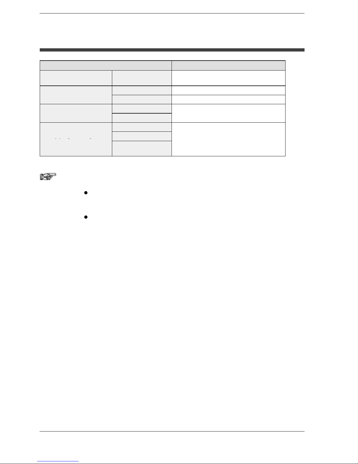
Type of programming tool Instruction used/function restrictions
Windows software
Conforms to IEC61131-3
FPWIN Pro Ver.4
All instructions and functions can be used.
FPWIN GR Ver.2
All instructions and functions can be used.
W
ind
ows software
FPWIN GR Ver.1
Not used
NPST-GR Ver.4
MS-DOSsof
tware
NPST-GR Ver.3
N
ot use
d
AFP1114V2
Handy programming unit
AFP1114
y
pg g
(FP programmer)
AFP1112A
AFP1112
Not
used
Notes
Precautions concerning programming tools
Programming tools used with the FPΣ require FPWIN Pro Ver. 4 or
later or Ver . 2 or a subsequent version of the FPWIN GR. Please be
aware that other tools cannot be used.
Either “FPWIN Pro Ver.4.1 or later” or “FPWIN GR Ver. 2.1 or later”
are necessary for use the C32T2 and C24R2 types control unit.
Page 13
Compatibility with the FP0
FPΣ
xii
Compatibility with the FP0
Program compatibility
The following points require attention if using FP0 programs on the FPΣ.
Pulse output function
With the FPΣ, please be aware that the following changes
have been made to instructions concerning pulse output.
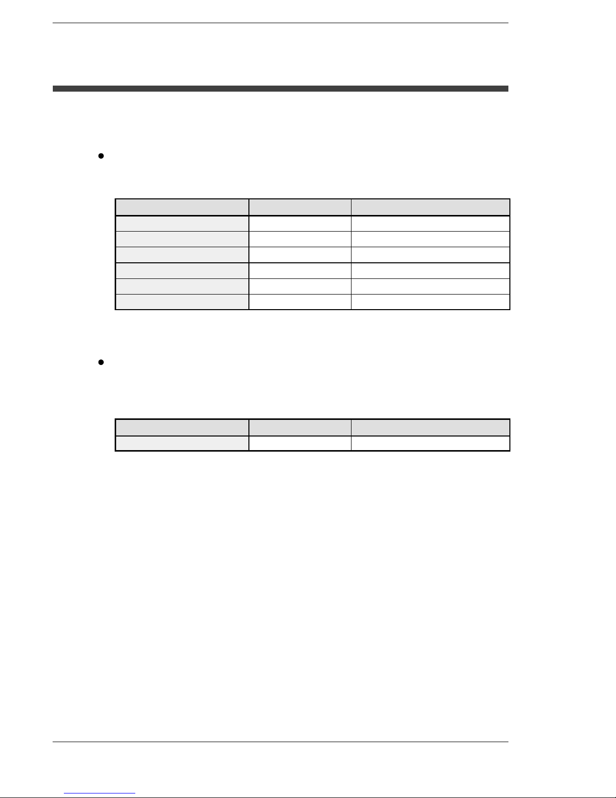
Instruction For the FP0 For the FPΣ
Trapezoidal control
F168 (SPD1) F171 (SPDH)
Jog feed
F169 (PLS) F172 (PLSH)
Data table control
None F174 (SP0H)
Linear interpolation control
None F175 (SPSH)
Circular interpolation control
None F176 (SPCH)
PWM output
F170 (PWM) F173 (PWMH)
* Linear and circular interpolation control can be used only with the
FPΣ Control Unit C32T2.
Serial data communication function
With the FPΣ, please be aware that the following changes
have been made to instructions concerning serial data
communication.
Instruction For the FP0 For the FPΣ
Serial data communication
F144 (TRNS) F159 (MTRN)
* The F159 (MTRN) instruction is used only with an FPΣ in which
the conventional F144 (TRNS) instruction has been set up to
correspond to multiple communication ports. Please be aware
that the conventional F144 (TRNS) instruction cannot be used
with the FPΣ.
Page 14

Chapter 1
Functions and Restrictions of the Unit
1.1 Features and Functions of the Unit 1 - 3................
1.2 Unit Types 1 - 6......................................
1.3 Restrictions on Unit Combinations 1 - 7.................
1.4 Programming Tools 1 - 9..............................
Page 15

FPΣFunctions and Restrictions of the Unit
1-2
Page 16
FPΣ 1.1 Features and Functions of the Unit
1-3
1.1 Features and Functions of the Unit
Powerful control capabilities
All of the functions of a mid-scale PLC are packed into the compact body size of the
32-point type FP0. A program capacity of 12 k steps is provided as a standard feature,
so you never have to worry about how much memory is left as you’re programming. In
addition, 32 k words are reserved for data registers, so large volumes of data can be
compiled and multiple operations can be processed without running out of memory.
A full range of communication functions
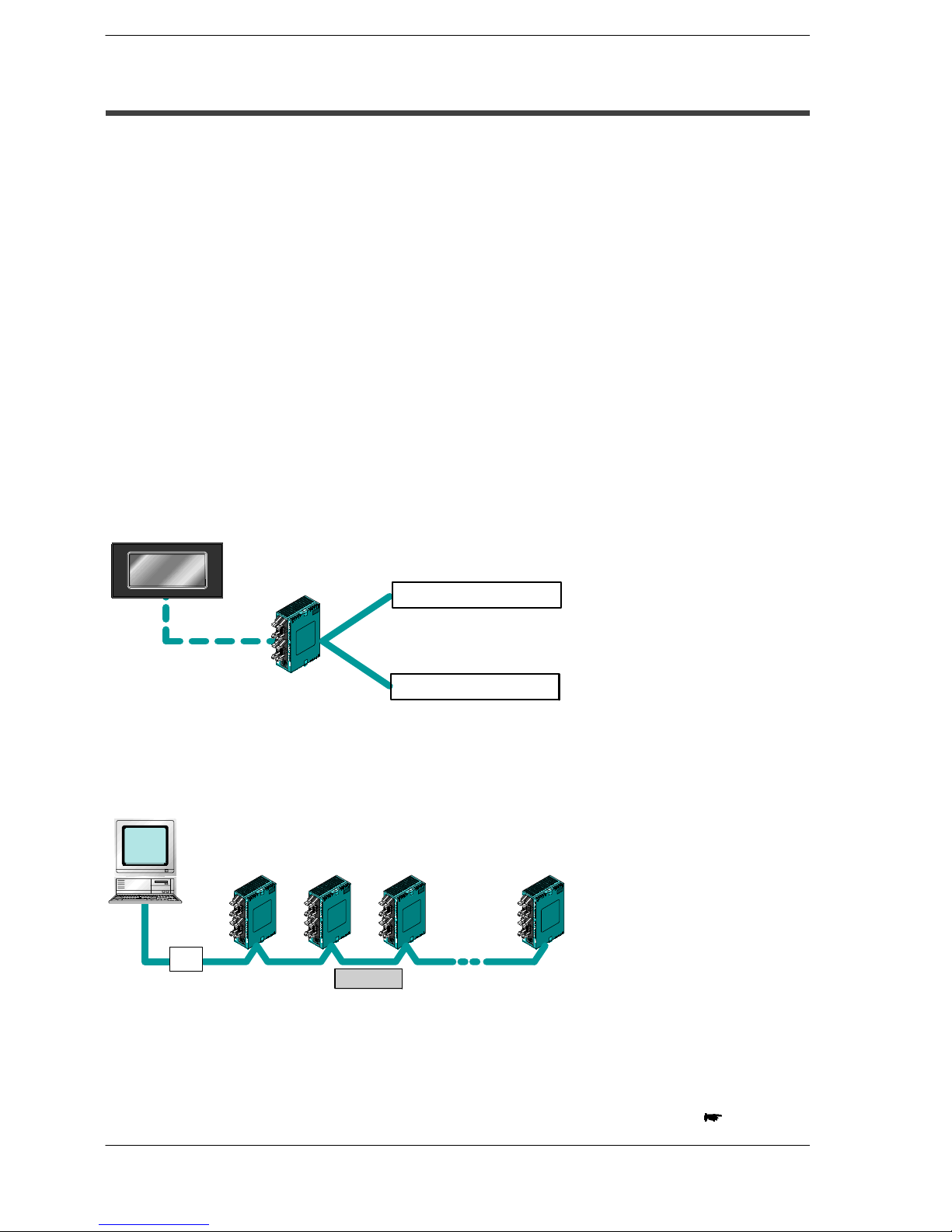
Using the Tool port (RS232C) provided as a standard feature on the main unit,
communication can be carried out with a display panel or computer. Additionally,
communication cassettes with RS232C and RS485 interfaces are available as an
option. Installing a 2-channel RS232C type communication cassette in the FPΣ makes
it possible to connect two devices with RS232C port. A full lineup of communication
functions means you can also work with 1:N communication and PLC link function (up
to 16 units).
Controlling two devices with RS232C port with one FP
Σ
Display panel
The Toolport can beused
toconnecta displaypanel
or other device.
Device with RS232C port
When using the 2-channel RS232C type communication cassette
Two devices with RS232C port can be connected.
Device with RS232C port
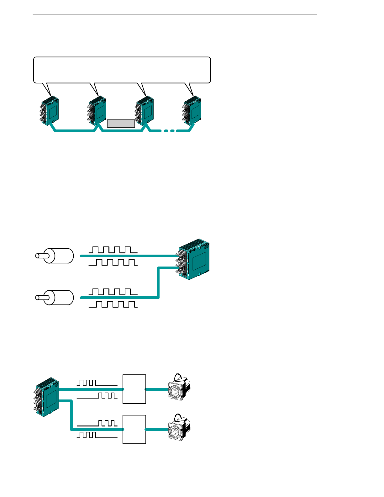
FPΣ
Figure 1: Features-communication (RS232C)
1:N communication possible with up to 99 stations (units)
Communication is possible with up to 99 units.
Commercial adapter
Computer
When using the 1-channel RS485 type communication cassette
FPΣ
No.1
FPΣ
No.2
FPΣ
No.3
FPΣ
No.99
RS485
Figure 2: Features-communication (C-NET)
next page
Page 17
FPΣ
Functions and Restrictions of the Unit
1-4
Data can be shared among up to 16 FPΣ units using
the PLC link function.
Data can be shared among the various PLCs using the PLC link function.
When using the 1-channel RS485 type communication cassette
FPΣ
No.1
FPΣ
No.2
FPΣ
No.3
FPΣ
No.16
RS485
Figure 3: Features-communication (PLC link)
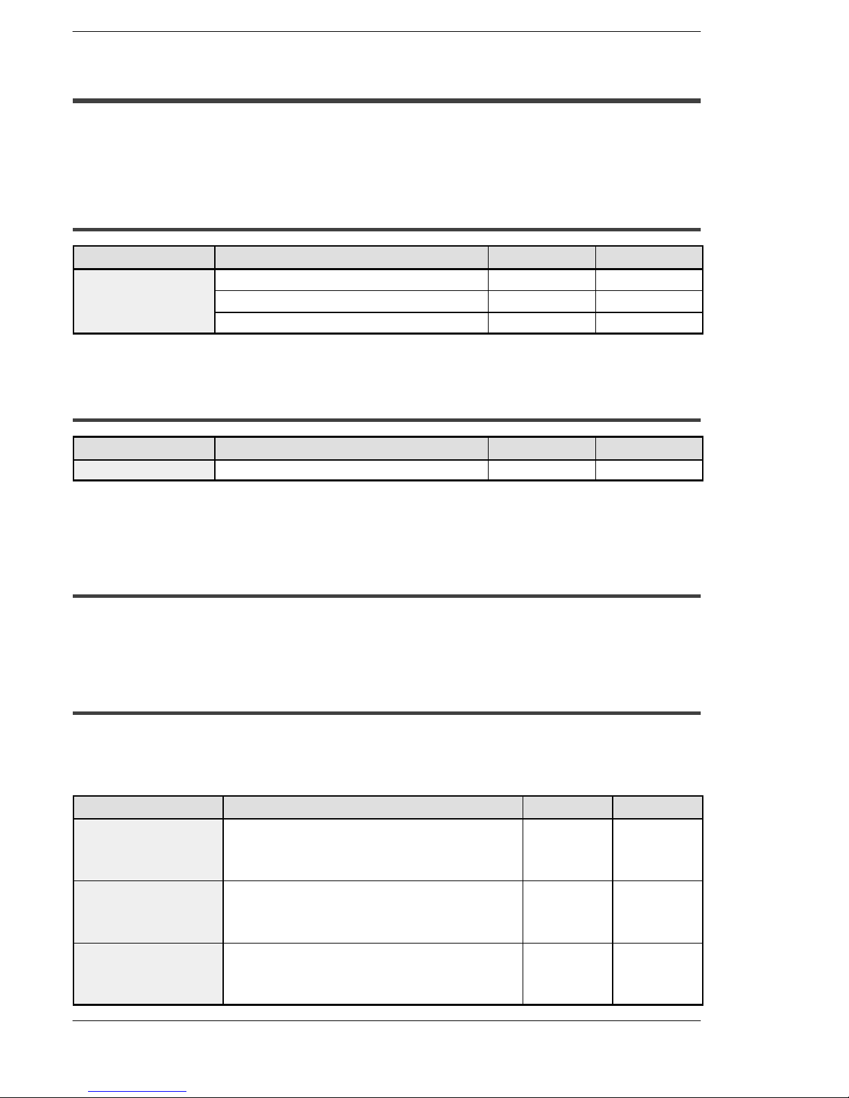
Positioning control supported through high-speed counter and pulse output
A high-speed counter and pulse output functions are provided as standard features.
The pulse output function supports frequencies of up to 100 kHz, enabling positioning
control using a stepping motor or servo motor.
Measurement using high-speed counter supported
Encoder
Single phase: Max. 50 kHz, Two-phase: Max. 20 kHz
Encoder
FPΣ
Increment input mode, decrement input mode, 2-phase input mode, individual input mode, and
direction discrimination mode are supported.
Pulse input
Pulse input
Figure 4: Features-High-speed counter
FPΣ
Positioning control based on pulse output supported
Pulse output
1-channel: Max. 100 kHz, 2-channel: Max. 60 kHz
Mortor
driver
CW/CCW and Pulse/sign outputs are supported.
Pulse output
Mortor
driver
Mortor
Mortor
Figure 5: Features-Pulse output
Page 18

FPΣ
1.1 Features and Functions of the Unit
1-5
Analog control supported
An analog potentiometer (volume dial) is provided as a standard feature. This can be
used in applications such as analog timers, without using the programming tools. An
analog unit is also available as the intelligent unit.
Page 19
FPΣ
Functions and Restrictions of the Unit
1-6
1.2 Unit Types
This section explains the type of unit used with the FPΣ and about the optional
communication cassette.
1.2.1 FPΣ Control Unit
Name Number of I/O points Part No. Product No.
Input: 16 points/Transistor output: 16 points FPG-C32T AFPG2543
FPΣ Control unit
Input: 16 points/Transistor output: 16 points FPG-C32T2 AFPG2643
Input: 16 points/Relay output: 8 points FPG-C24R2 AFPG2423
1.2.2 FPΣ Expansion Unit
Name Number of I/O points Part No. Product No.
FPΣ expansion I/O unit Input: 32 points/Transistor output: 32 points FPG-XY64D2T AFPG3467
* The FPΣ expansion I/O unit can be used for “FPG-C32T2 and FPG-C24R2” FPΣ
control units.
1.2.3 Units for FP0 and FPΣ
The FPΣ can be used the FP0 series expansion I/O unit, power supply unit, and
intelligent unit.
1.2.4 Communication Cassette
A detachable communication cassette (optional) should be used when using the
various functions such as the computer link, serial data communication, and PLC link
functions.
Name Description Part No. Product No.
FPΣ Communication
cassette 1-channel
RS232C type
This communication cassette is a 1-channel unit with
a five-wire RS232C port. It supports 1 : 1 computer
links and general-purpose serial communication. RS/
CS control is possible.
FPG-COM1 AFPG801
FPΣ Communication
cassette 2-channel
RS232C type
This communication cassette is a 2-channel unit with
a three-wire RS232C port. It supports 1 : 1 computer
links and general-purpose serial communication.
Communication with two external devices is possible.
FPG-COM2 AFPG802
FPΣ Communication
cassette 1-channel
RS485 type
This communication cassette is a 1-channel unit with
a two-wire RS485 port. It supports 1 : N computer
links(C-NET),general-purposeserialcommunication,
and a PLC link.
FPG-COM3 AFPG803
Page 20
FPΣ
1.3 Restrictions on Unit Combinations
1-7
1.3 Restrictions on Unit Combinations
This section contains restrictions on unit combinations.
1.3.1 Restrictions on the Number of Expansion Units
(for FP0 expansion unit)
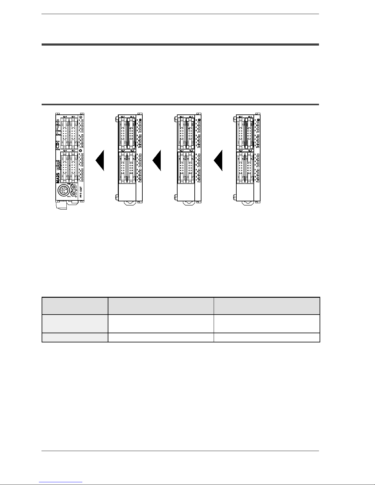
Control unit Unit 1 for expansion
(Maximum possible
expansion is with a
total of three units)
Unit 2 for expansion Unit 3 for expansion
Figure 6: Restriction on unit combinations
Up to three expansion units can be added at the right of the FPΣ, these expansion units being
either expansion units or intelligent units from the earlier FP0 series, or a combination of the
two.
There are no restrictions on the type and the order in which expansion units are installed.
A combination of relay output types and transistor output types is also possible.
Controllable I/O Points
Type of control unit
Number of I/O points when using
control unit
Number of I/O points when using
FP0 expansion unit
FPG-C32T
FPG-C32T2
32 points Max. 128 points
FPG-C24R2 24 points Max. 120 points
Page 21
FPΣ
Functions and Restrictions of the Unit
1-8
1.3.2 Restrictions on the Number of Units for Expansion (for FPΣ
expansion unit)
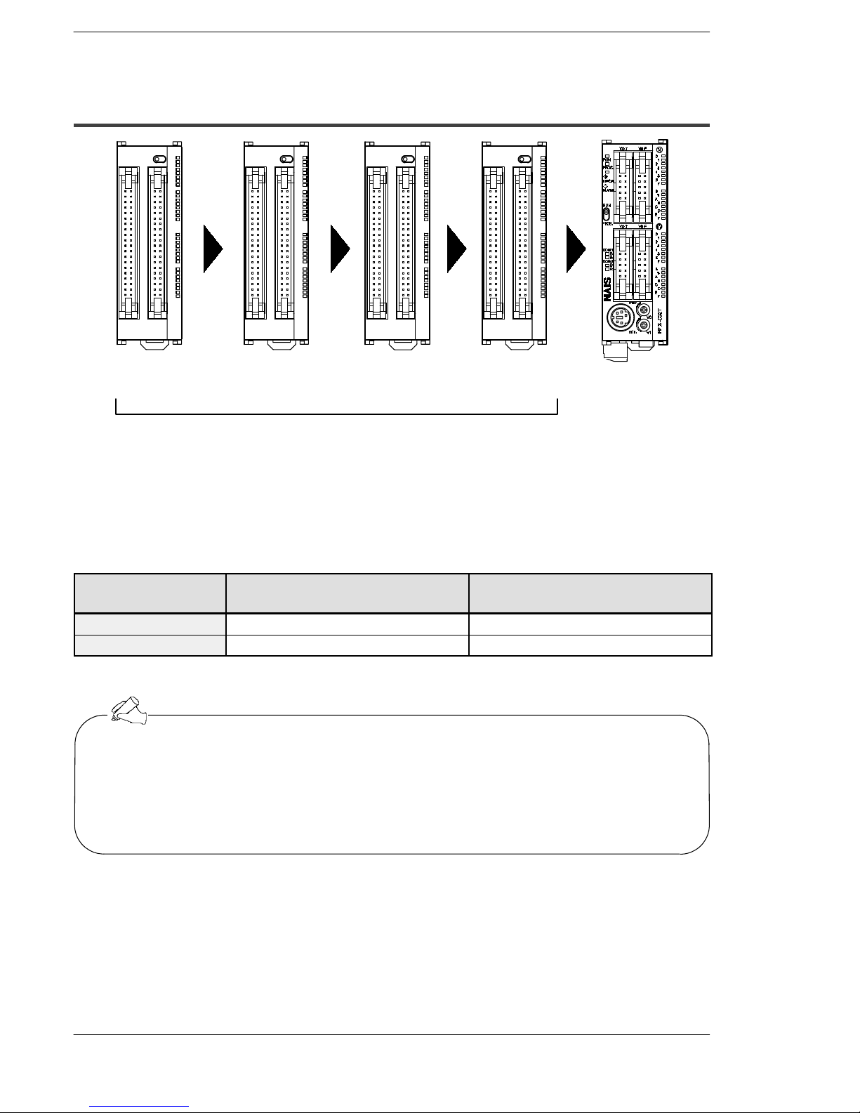
Control unitExpansion unit 1Expansion unit 2Expansion unit 3Expansion unit 4
Max. possible expansion is with a total of four units.
Up to four dedicated FPΣ expansion units can be added at the left of the FPΣ.
The 64 points type expansion unit consist of 32 input points and 32 transistor output
points.
Controllable I/O Points
Type of control unit
Number of I/O points when using
control unit
Number of I/O points when using
FPΣ expansion unit
FPG-C32T2 32 points Max. 288 points
FPG-C24R2 24 points Max. 280 points
The FPΣ expansion unit cannot be used for FPG-C32T.
Tip
If using FP0 expansion units and FPΣ expansion units in combination, the number
of input and output points can be expanded to a maximum of 384 points for the
FPG-C32T2 and 376 points for the FPG-C24R2.
Page 22
FPΣ
1.4 Programming Tools
1-9
1.4 Programming Tools
This section explains about the programming tools for FPΣ.
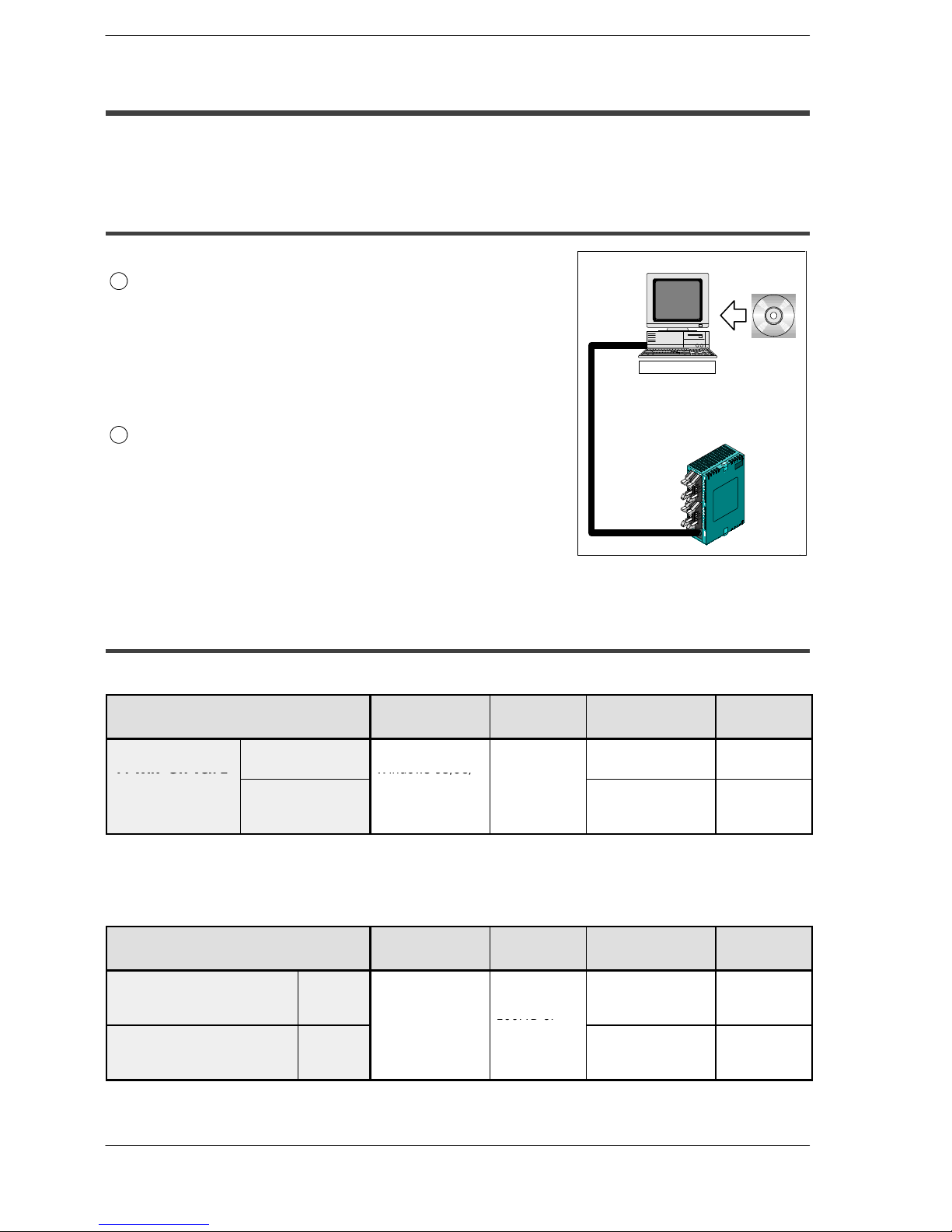
1.4.1 Tools Needed for Programming
FPΣ
Computer
PC connection cable
1
Programming tool software
The tool software can also be used with the FP series.
The “FPWIN Pro Ver. 4” or “FPWIN GR Ver. 2” Windows
software is used with the FPΣ.
The earlier FPWIN GR Ver. 1x, NPST-GR, and FP Programmer cannot be used.
2
PC connection cable
This cable needed for connection between the FPΣ and
the computer.
Programming
tool software
FPΣ
Figure 7: Programming tools
1.4.2 Software Environment and Suitable Cable
Standard ladder diagram tool software “FPWIN-GR Ver.2”
Type of software
OS (Operating
system)
Hard disk
capacity
Part No.
Product
No.
FPWIN-GR Ver. 2
English-language
software
Windows 95/98/
FPWINGRF-EN2 AFPS10520
FPWIN
GRVer.2
English-language
menu
Upgrade (to
upgrade from
Ver.1.1)
Windows
95/98/
Me/2000/NT
(Ver. 4.0 or later)
30MB or more
FPWINGRR-EN2 AFPS10520R
Conforms to IEC61131-3 programming tool software “FPWIN-Pro Ver.4”
Type of software
OS (Operating
system)
Hard disk
capacity
Part No.
Product
No.
FPWIN Pro Ver. 4 Full type
(for all type FP series PLC)
Englishlanguage
menu
Windows 95/98/
100MB or
FPWINPROF-EN4 AFPS50540
FPWIN Pro Ver. 4 Small type
(for FP0, FPΣ, FP1, and
FP-M)
Englishlanguage
menu
Me/
2000
/NT
(Ver. 4.0 or later)
100MB
or
more
FPWINPROS-EN4 AFPS51540
Page 23

FPΣ
Functions and Restrictions of the Unit
1-10
Type of computer and suitable cable
Type of computer Cable Cable specification
IBM PC/AT or
Part No.: AFC8503 D-Sub 9-pin female-Mini DIN 5-pin male
IBM
PC/A
T
or
its compatible machine
Part No.: AFC8513 D-Sub 25-pin male-Mini DIN 5-pin male
Page 24

Chapter 2
Specifications and Functions of Control
Unit
2.1 Parts and Functions 2 - 3.............................
2.2 Input and Output Specifications 2 - 7...................
2.3 Terminal Layout Diagram 2 - 12........................
Page 25

FPΣSpecifications and Functions of Control Unit
2-2
Page 26
FPΣ 2.1 Parts and Functions
2-3
2.1 Parts and Functions
This section explains about the parts and functions of FPΣ control unit.
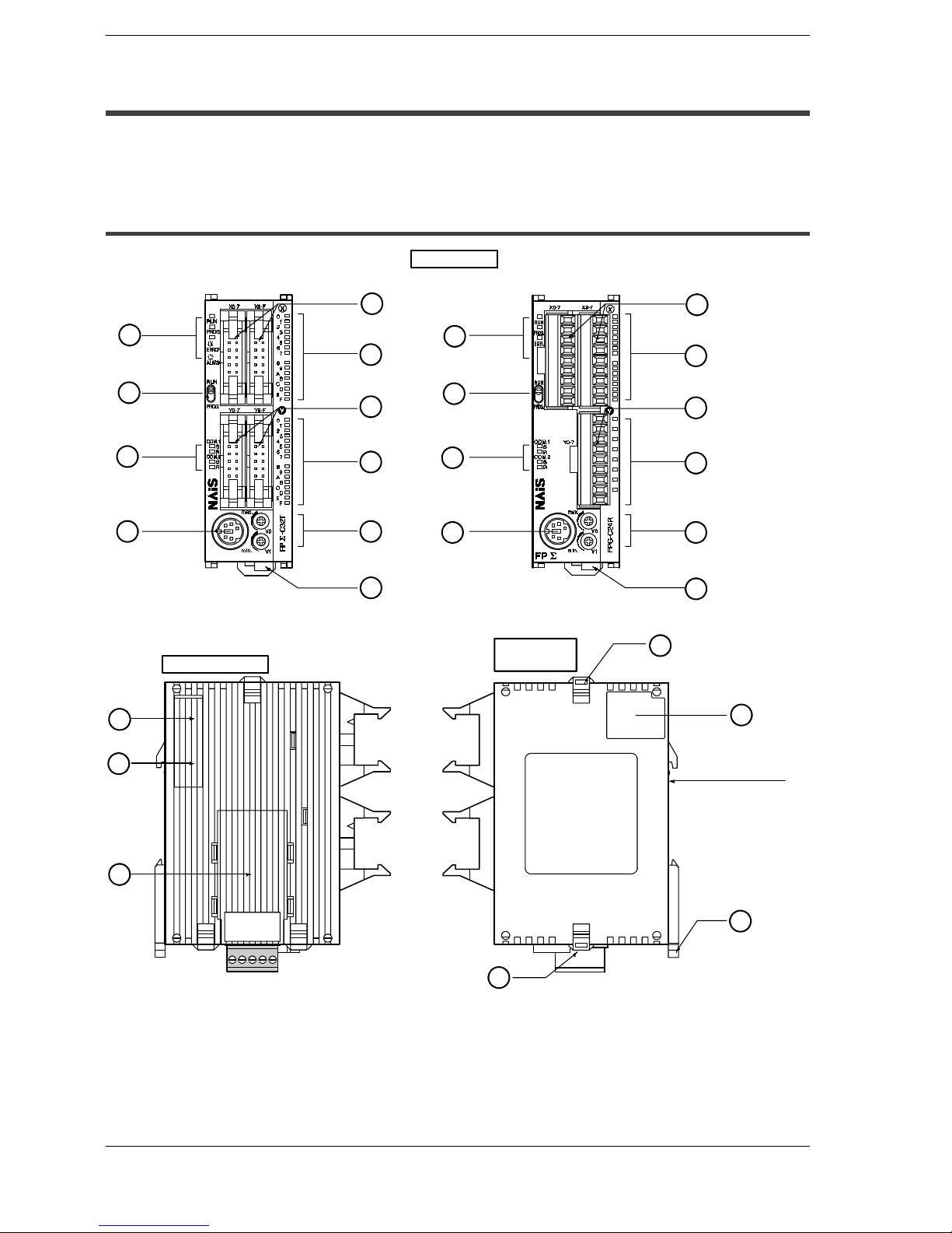
2.1.1 Parts and Functions
EXPANSION
CONNECTOR
FPG-C32T
FPG-C32T2
FPG-C24R2
Front view
Left side view
Right side
view
DIN standard rail
attachment
For all type control unit
1
2
3
4
5
6
7
8
9
10
1
2
3
4
5
6
7
8
9
10
11
13
12
14
14
15
16
Figure 8: FPΣ Parts and Functions
Page 27
FPΣ
Specifications and Functions of Control Unit
2-4
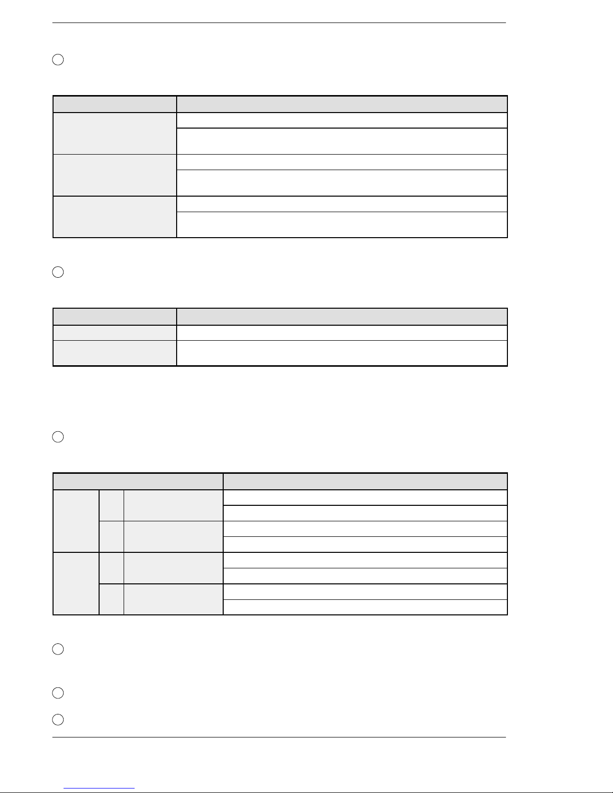
1
Status indicator LEDs
These LEDs display the current mode of operation or the occurrence of an error.
LED LED and operation status
RUN (green) Lights when in the RUN mode and indicates that the program is being executed.
It flashes during forced input/output.
(The RUN and PROG LEDs flash alternately.)
PROG. (green) Lights when in the PROG. mode and indicates that operation has stopped.
It flashes during forced input/output.
(The RUN and PROG LEDs flash alternately.)
ERROR/ALARM (red) Flashes when an error is detected during the self-diagnostic function.
Lights if a hardware error occurs, or if operation slows because of the program, and
the watchdog timer is activated.
2
RUN/PROG. mode switch
This switch is used to change the operation mode of the PLC.
Switch position Operation mode
RUN (upward) This sets the RUN mode. The program is executed and operation begins.
PROG. (downward) This sets the PROG. mode.The operation stops. In this mode, programming canbe
done using tools.
When performing remote switching from the programming tool, the position of the mode
switch and the actual mode of operation may differ. Verify the mode with the status indicator
LED. Otherwise, restart the FPΣ and change the mode of operation with the RUN/PROG.
mode switch.
3
Communication status LEDs
These display the communication status of the COM.1 and COM.2 ports.
LED LED and communication status
COM.1 S Transmitted data
Flashes while data is being transmitted
monitor
Goes out when no data is being transmitted
R Received data
Flashes while data is being received
monitor
Goes out when no data is being received
COM.2 S Transmitted data mo-
Flashes while data is being transmitted
nitor
Goes out when no data is being transmitted
R Received data
Flashes while data is being received
monitor
Goes out when no data is being received
4
Tool port (RS232C)
This port is used to connect a programming tool.
5
Input connector (10 pins × 2)
6
Input indicator LEDs
Page 28
FPΣ
2.1 Parts and Functions
2-5
7
Output connector (10 pins × 2)
8
Output indicator LEDs
9
Analog potentiometer (analog dial)
Turning this dial changes the values of special data registers DT90040 and DT90041 within
the range of K0 to K1000. It can be used for analog timers and other applications.
10
Power supply connector (24 V DC)
Supply 24 V DC. It is connected using the power supply cable (AFP0581) that comes with the
unit.
11
Left-side connector for FPΣexpansion
This is used to connect dedicated FPΣ expansion units on the left side of the control unit with
the internal circuits.
*The FPG-C32T2 and FPG-C24R2 control units are equipped with this connector, but the
FPG-C32T is not.
12
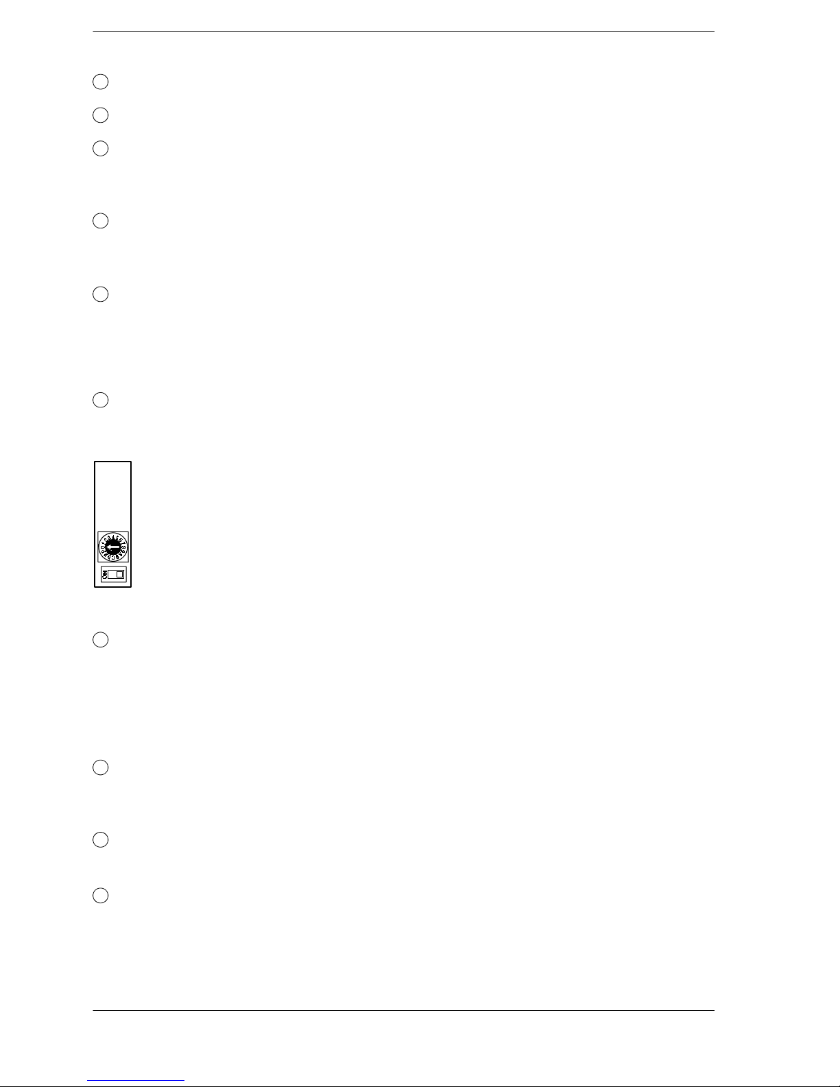
Unit No. (Station No.) setting switch
This unit No. (station No.) is specified when using the communication functions provided on
the optional communication cassettes.
The unit No. (station No.) setting switch is located under the cover on the back of the
unit. Specify the unit (station) number using the selector switch and the dial.
Figure 9: FPΣ Parts and Functions (Unit No. setting switch)
13
Communication cassette (option)
This is the optional cassette type adapter used when communication is carried out.
Any one of the following the cassette types may be installed.
- 1-channel RS232C type
- 2-channel RS232C type
- 1-channel RS485 type
14
Expansion hook
This hook is used to secure expansion units. The hook is also used for installation on flat type
mounting plate (AFP0804).
15
Right-side connector for FP0 expansion
Connects an expansion unit to the internal circuit of the control unit.
16
DIN rail attachment lever
The FPΣ unit enables attachment at a touch to a DIN rail. The lever is also used for
installation on slim 30 type mounting plate (AFP0811).
Page 29
FPΣ
Specifications and Functions of Control Unit
2-6
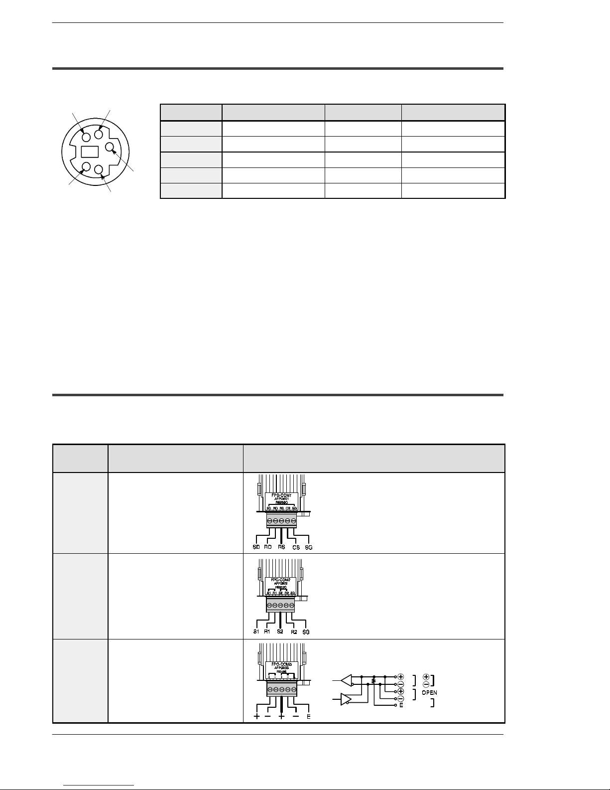
2.1.2 Tool Port Specification
A commercial mini-DIN 5-pin connector is used for the Tool port on the control unit.
Pin no. Signal name Abbreviation Signal direction
1
Signal Ground SG —
2
Transmitted Data SD Unit → External device
3
Received Data RD Unit ← External device
4
(Not used) — —
5
+5V +5V Unit → External device
Figure 10: FPΣ Parts and Functions (Tool port)
The following are the default settings set when the unit is shipped from the factory .The
system registers should be used to change these.
- Baud rate 9600 bps......
- Character bit 8 bit...
- Parity check Odd parity....
- Stop bit length 1 bit..
2.1.3 Communication Cassette
The detachable communication cassette (optional) can be selected from among the
three types shown below.
Type Applicable communication
function
Terminal layout diagram
1-channel
RS232C
type
Computer link
General-purpose serial
communication
SD: Transmitted Data (Output)
RD: Received Data (Input)
RS: Request to Send (Output)
CS: Clear to Send (Input)
SG: Signal Ground
2-channel
RS232C
type
Computer link
General-purpose serial
communication
S1: Transmitted Data (Output) (COM.1)
R1: Received Data (Input) (COM.1)
S2: Transmitted Data (Output) (COM.2)
R2: Received Data (Input) (COM.2)
SG: Signal Ground (COM.1 and 2)
1-channel
RS485 type
Computer link
General-purpose serial
communication
PLC link
General
station
Terminal
station
Short
1
3
5
4
2
Page 30
FPΣ
2.2 Input and Output Specifications
2-7
2.2 Input and Output Specifications
This section contains input and output specifications of FPΣ control unit.
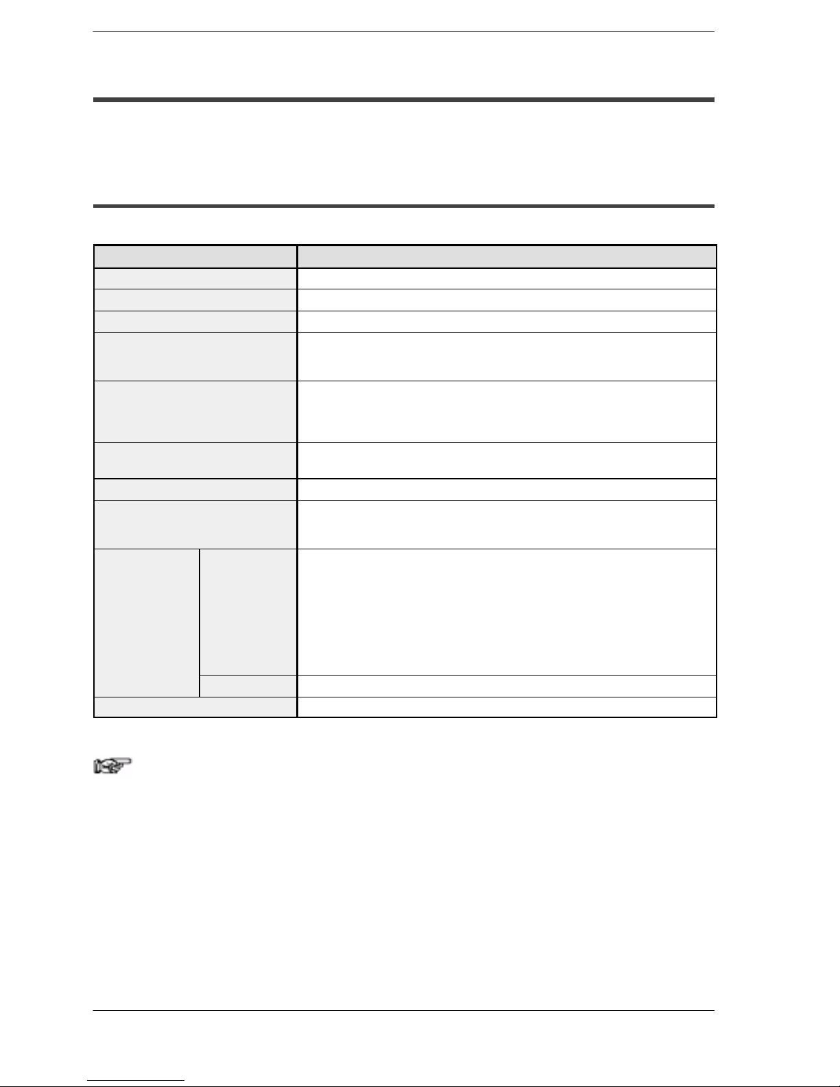
2.2.1 Input Specifications
Input specifications (for all type)
Item Description
Insulation method
Optical coupler
Rated input voltage
24 V DC
Operating voltage range
21.6 to 26.4 V DC
Rated input current
For X0, X1, X3, X4:approx. 8 mA
For X2, X5 to X7: approx. 4.3 mA
For X8 to XF: approx. 3.5 mA
Input points per common
For C32T, C32T2: 16 points/common
For C24R2: 8 points/common
(Either the positive or negative of the input powersupply can be connected to
common terminal.)
Min. on voltage/Min. on current
For X0, X1, X3, X4:19.2 V DC/6 mA
For X2, X5 to XF: 19.2V DC/3 mA
Max. off voltage/Max. off current
2.4 V DC/1.3 mA
Input impedance
For X0, X1, X3, X4:3 kΩ
For X2, X5 to X7: 5.6 kΩ
For X8 to XF: 6.8 kΩ
Response time off → on
For input X0, X1, X3, X4:
1 ms or less: normal input
5 µs or less: high-speed counter, pulse catch, interrupt input settings
For input X2, X5 to X7:
1 ms or less: normal input
100 µs or less: high-speed counter, pulse catch, interrupt input settings
For input X8 to XF:
1 ms or less: normal input only
on → off
Same as above
Operating mode indicator
LED display
Note
X0 through X7 are inputs for the high-speed counter and have a
fast response time. If used as normal inputs, we recommend
inserting a timer in the ladder program as chattering and noise
may be interpreted as an input signal.
Also, the above specifications apply when the rated input voltage
is 24 VDC and the temperature is 25°C/70°F.
Page 31
FPΣ
Specifications and Functions of Control Unit
2-8
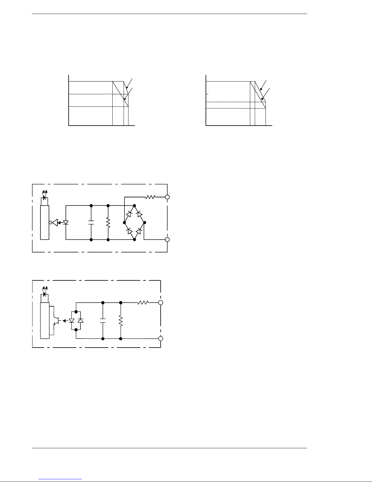
Limitations on number of simultaneous input on points
Keep the number of input points per common which are simultaneously on within the
following range as determined by the temperature.
16
8
[C32T]
at 24 V DC
at 26.4 V DC
12
16
7
[C24R]
12
9
at 24 V DC
at 26.4 V DC
46/
107.8
52/
118.6
55/
124
Ambient temperature (°C/°F)
Number of
points per
common
which are simultaneous
on
46/
107.8
48/
118.4
55/
124
Ambient temperature (°C/°F)
Number of
points per
common
which are simultaneous
on
Figure 11: FPΣ Limitations on number of simultaneous input on points
Internal circuit diagram
[X0, X1, X3, X4]
Internal circuit
510 Ω
3kΩ
Xn
COM
Figure 12: FPΣ Internal circuit diagram (Input-1)
Xn
COM
[X2, X5 to XF]
Internal circuit
R1
R2
For X2 and X5 to X7, R1: 5.6 kΩ,R2:1kΩ
For X8 to XF, R1: 6.8 kΩ, R2: 820 Ω
Figure 13: FPΣ Internal circuit diagram (Input-2)
Page 32
FPΣ
2.2 Input and Output Specifications
2-9
2.2.2 Output Specifications
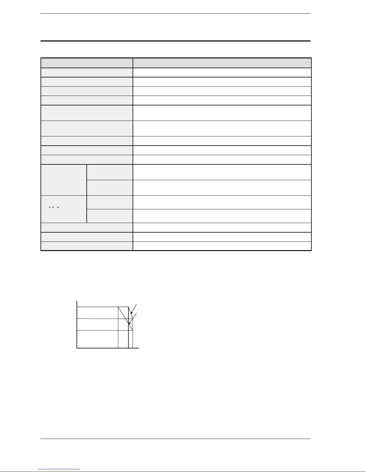
Transistor output specifications (for C32T and C32T2)
Item Description
Insulation method Optical coupler
Output type Open collector (NPN)
Rated load voltage 5to24VDC
Operating load voltage range 4.75 to 26.4 V DC
Max. load current For Y0, Y1, Y3, Y4:0.3 A
For Y2, Y5 to YF: 0.1 A
Max. surge current ForY0, Y1, Y3, Y4:0.9 A
For Y2, Y5 to YF: 0.5 A
Output points per common 16 points/common
Off state leakage current 100 µA or less
On state voltage drop 0.5 V or less
Response time off → on For Y0, Y1, Y3, Y4 (at 15 mA or more): 2 µs or less
For Y2, Y5 to YF: 0.2 ms or less
on → off For Y0, Y1, Y3, Y4 (at 15 mA or more): 8 µs or less
For Y2, Y5 to YF: 0.5 ms or less
External power
supply for
Voltage 21.6 to 26.4 V DC
supply
for
driving internal
circuit
Current 70 mA or less
Surge absorber Zener diode
Operating mode indicator LED display
Phase fault protection Thermal protection for Y2, Y5 to YF
Limitations on number of simultaneous output on points
Keep the number of output points per common which are simultaneously on within the
following range as determined by the ambient temperature.
16
8
46/
107.8
52/
118.6
55/
124
[C32T]
at 24 V DC
at 26.4 V DC
12
Ambient temperature (°C/°F)
Number of
points per
common
which are simultaneous
on
Figure 14: FPΣ Limitations on number of simultaneous output on points
Page 33
FPΣ
Specifications and Functions of Control Unit
2-10
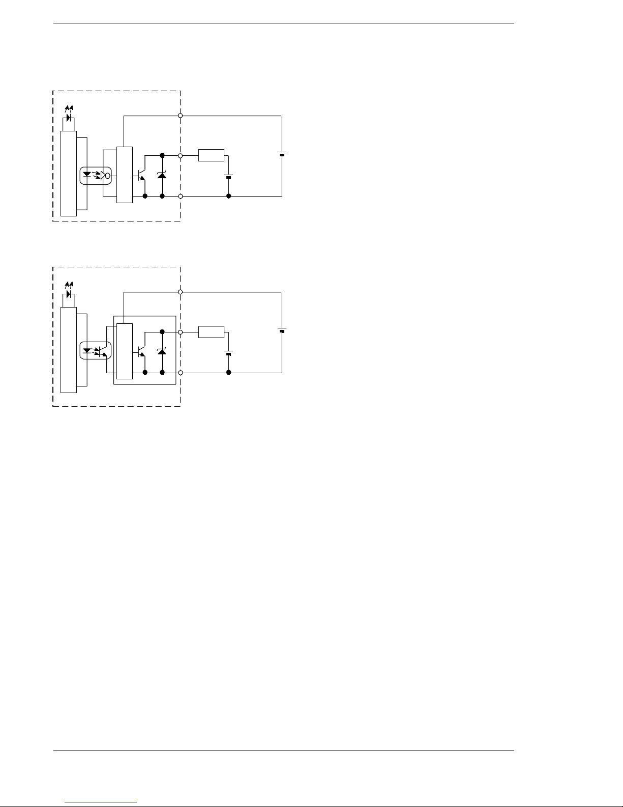
Internal circuit diagram
Internal circuit
Output indicator LED
+
Output
Load
0V
Load
power supply
5to24VDC
Output circuit
External power supply
24 V DC
[Y0, Y1, Y3, Y4]
Figure 15: FPΣ Internal circuit diagram (output-1)
[Y2, Y5 to YF]
Internal circuit
Output indicator LED
Output circuit
+
Output
Load
0V
Load
power supply
5to24VDC
External power supply
24 V DC
Phase fault
protection circuit
Figure 16: FPΣ Internal circuit diagram (output-2)
Page 34
FPΣ
2.2 Input and Output Specifications
2-11
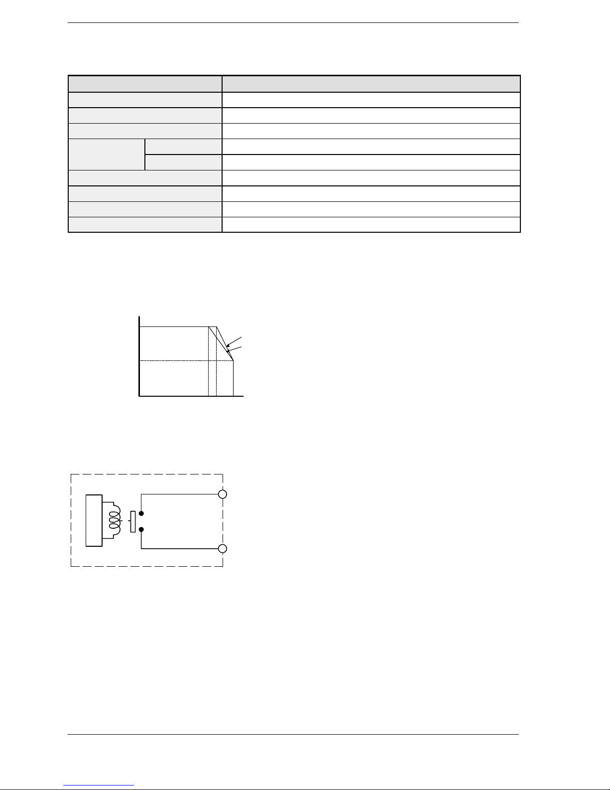
Relay output specifications (for C24R2)
Item Description
Output type 1a (1 Form A, Normally open)
Rated control capacity 2 A 250 V AC, 2 A 20 V DC (4.5 A per common or later)
Output points per common 8 points/common
Response time off → on Approx. 10 ms
on → off Approx. 8 ms
Mechanical lifetime Min. 20,000,000 operations
Electrical lifetime Min. 100,000 operations
Surge absorber Operating mode indicator LED display
Limitations on number of simultaneous output on points
Keep the number of output points which are simultaneously on within the following
range as determined by the ambient temperature.
8
46/
107.8
48/
118.4
55/
124
[C24R]
at 24 V DC
at 26.4 V DC
4
Ambient temperature (°C/°F)
Number of
points per
common
which are
simultaneous
on
Internal circuit diagram
Internal circuit
Yn
COM
[C24R]
Page 35
FPΣ
Specifications and Functions of Control Unit
2-12
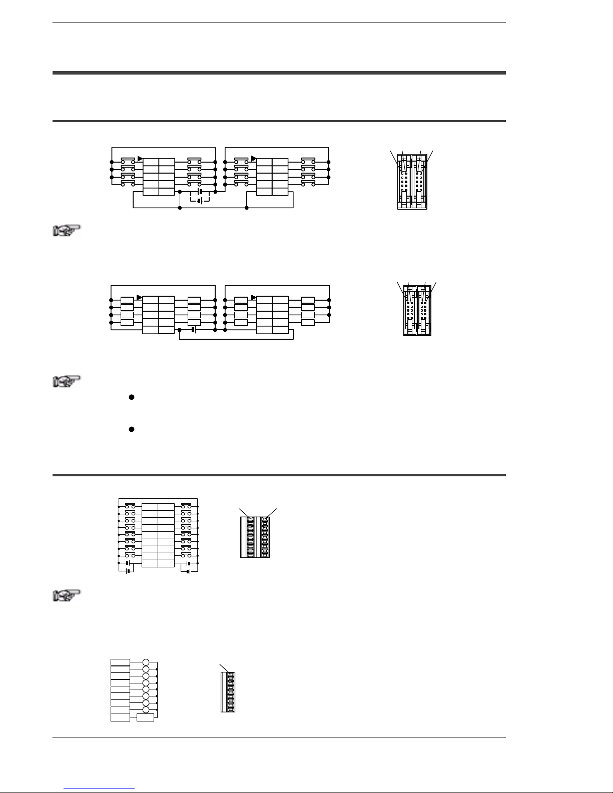
2.3 Terminal Layout Diagram
2.3.1 Control Unit (for C32T and C32T2)
Input
X0- 7
COM
X5
X7
X1
X3
COM
X4
X6
X0
X2
COM
XD
XF
X9
XB
COM
XC
XE
X8
XA
X0 X1
X8- F
X8 X9
Note
The four COM terminals of input circuit are connected internally.
Output
Y5
Y7
Y1
Y3
(+)
Y4
Y6
Y0
Y2
L
L
L
L
L
L
L
L
YD
YF
Y9
YB
(+)
YC
YE
Y8
YA
L
L
L
L
L
L
L
L
Y0
Y1
Y9
Y8
(–)
Y0- 7 Y8- F
(–)
(Connector front view)
Figure 17: FPΣ Terminal layout diagram (I/O connector)
Notes
The two (+) terminals of output circuit are connected
internally.
The two (–) terminals of output circuit are connected internally.
2.3.2 Control Unit (for C24R2)
Input
X0 X8
COM
X5
X7
X1
X3
COM
XD
XF
X9
XB
XC
XE
X8
XA
X4
X6
X0
X2
Note
The two COM terminals of input circuit are not connected
internally.
Output
Y0
Y5
Y7
Y1
Y3
Y4
Y6
Y0
Y2
COM
L
L
L
L
L
L
L
L
Power
(Connector front view)
Page 36

Chapter 3
Expansion
3.1 Type of Expansion Unit 3 - 3..........................
3.2 Expansion Method of Units for FP0 and FPΣ 3 - 4........
3.3 Expansion Method of FPΣ Expansion Unit 3 - 5..........
3.4 Specifications of FPΣ Expansion Unit 3 - 6..............
Page 37

FPΣExpansion
3-2
Page 38
FPΣ 3.1 Type of Expansion Unit
3-3
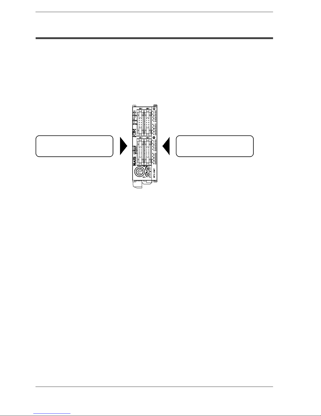
3.1 Type of Expansion Unit
ExpansionI/O units, power supply units,andintelligent units from the earlier FP0 series
can be used with the FPΣ, in addition to the dedicated expansion units designed
expressly for the FPΣ.
Expansion units used for the earlier FP0 series are connected on the right side of the
control unit, just as they were with the FP0. Dedicated expansion units for the FPΣ are
connected to the left side of the control unit.
Expansion on left side of control unit
FPΣ dedicated
expansion unit
Expansion possible up to 4 units
Control unit
Expansion on right side of control unit
FP0 expansion unit
Expansion possible up to 3 units
Page 39
FPΣ
Expansion
3-4
3.2 Expansion Method of Units for FP0 and FPΣ
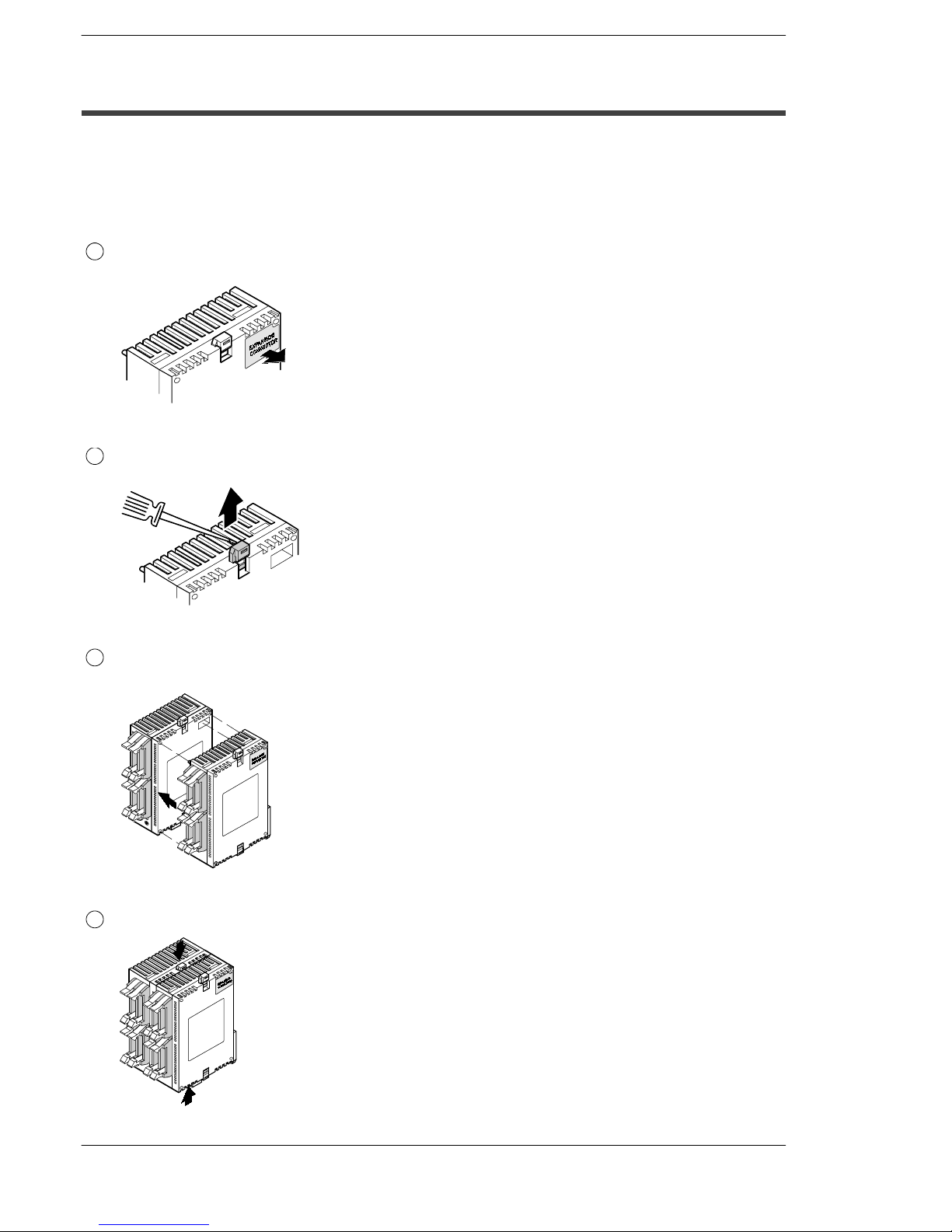
The previously available expansion I/O unit or intelligent unit for FP0 is expanded by
connecting to the right side of control unit.
Because unit expansion is done using the right-side connector for FP0 expansion and
expansion hook on the side of the unit, no expansion cable is needed.
1
Peel the seal on the side of the unit so that the internal right-side connector for FP0
expansion is exposed.
Peel the seal.
Figure 18: Expansion method procedure-1
2
Raise the expansion hooks on the top and bottom sides of the unit with a screwdriver.
Figure 19: Expansion method procedure-2
3
Align the pins and holes in the four corners of the control unit and expansion unit, and
insert the pins into the holes so that there is no gap between the units.
Figure 20: Expansion method procedure-3
4
Press down the expansion hooks raised in step 2 to secure the unit.
Figure 21: Expansion method procedure-4
Page 40
FPΣ
3.3 Expansion Method of FPΣ Expansion Unit
3-5
3.3 Expansion Method of FPΣ Expansion Unit
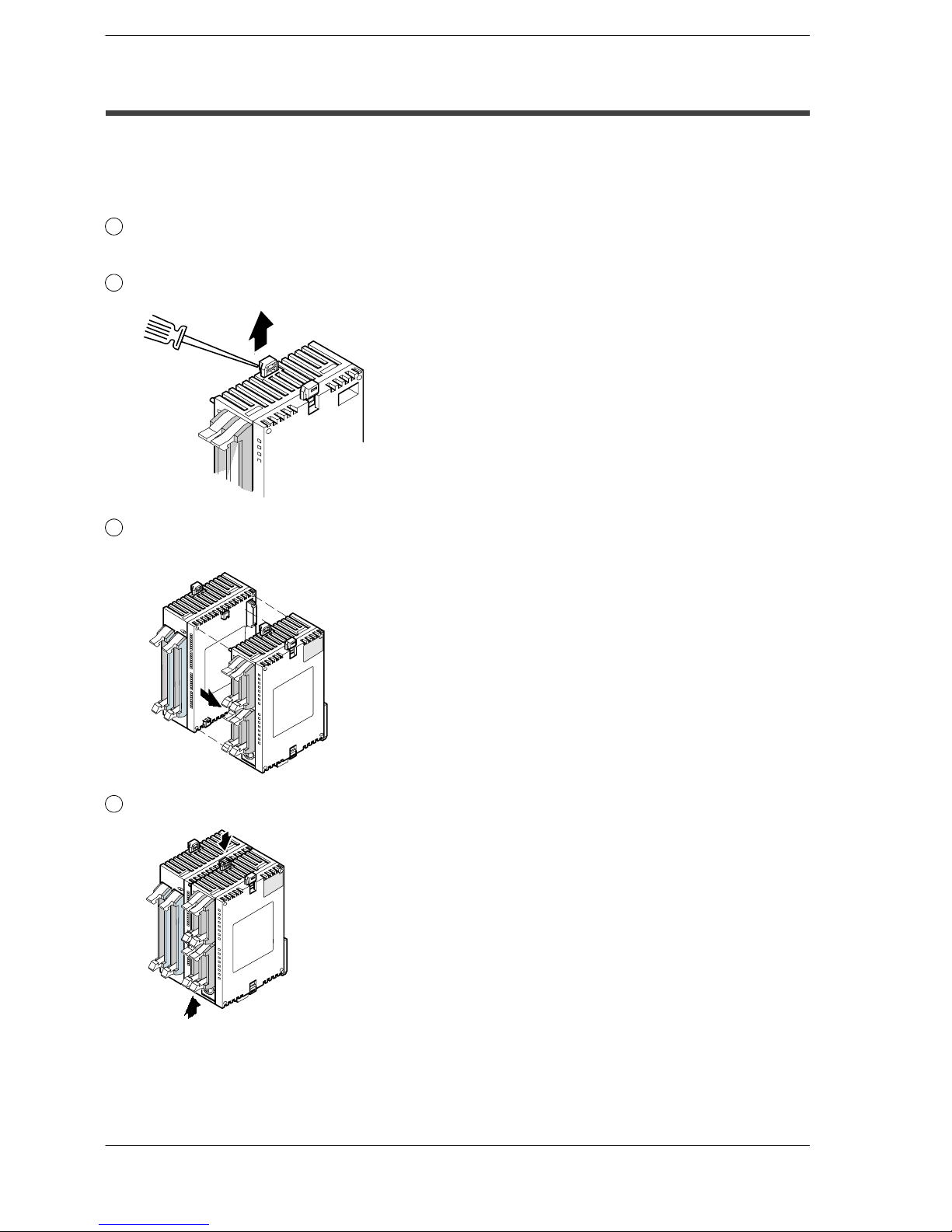
The dedicated expansion unit for FPΣ is expanded by connecting to the left side of the
control unit. Because unit expansion is done using the left-side connector for FPΣ
expansion and expansion hook on the side of the unit, no expansion cable is needed.
1
Remove the cover on the left side of the unit so that the internal left-side connector for
FPΣ expansion is exposed.
2
Raise the expansion hooks on the top and bottom sides of the unit with a screwdriver.
3
Align the pins and holes in the four corners of the control unit and expansion unit, and
insert the pins into the holes so that there is no gap between the units.
4
Press down the expansion hooks raised in step 2 to secure the unit.
Page 41
FPΣ
Expansion
3-6
3.4 Specifications of FPΣ Expansion Unit
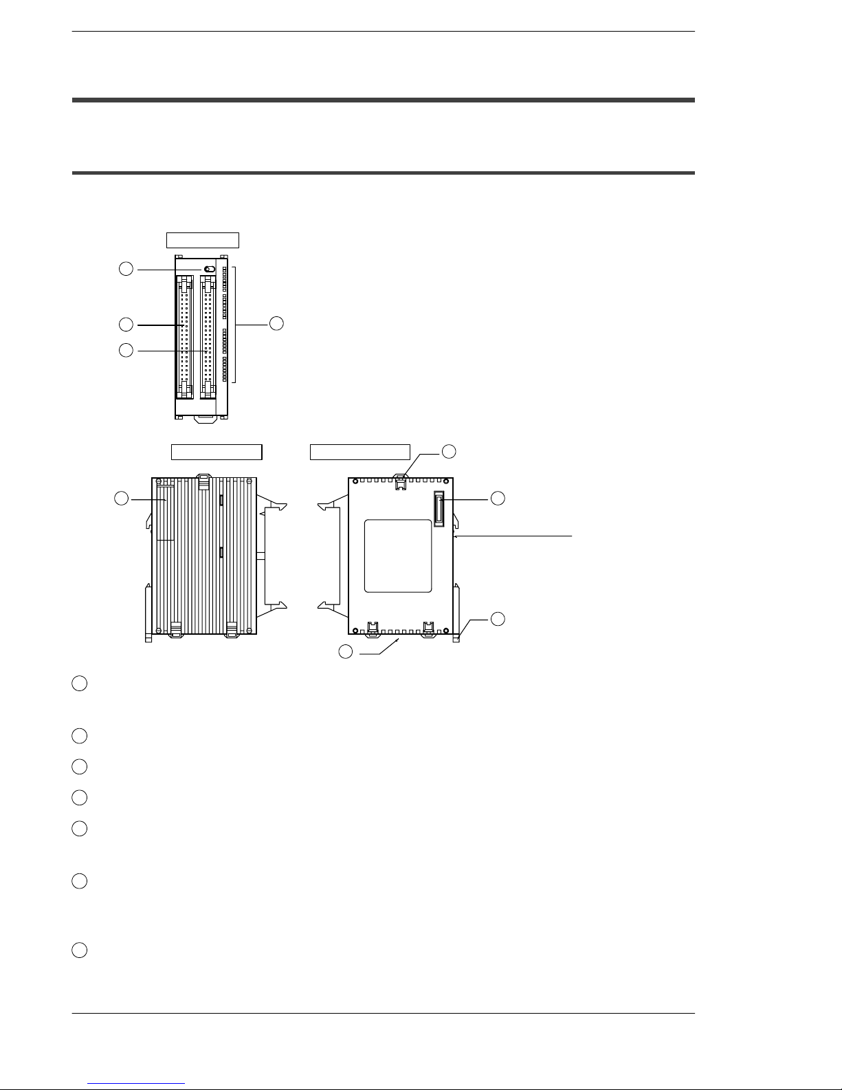
3.4.1 FPΣ Expansion I/O Unit
Parts and Functions
FPG-XY64D2T
(Input: 32 points / Transistor output: 32 points)
DIN standard
rail attachment
Front view
Left side view Right side view
1
2
3
4
5
6
5
7
6
1
LED display selection switch
Switches between the input (32 points) and output (32 points) of the LED display.
2
Input connector (40 pins)
3
Output connector (40 pins)
4
Input and Output indicator LEDs
5
FPΣ expansion connector
This expansion connector is used to connect the dedicated unit for FPΣ.
6
Expansion hook
This hook is used to secure expansion unit. The hook is also used for installation on FP0
mounting plate (flat type)(Part No.: AFP0804).
7
DIN rail attachment lever
The expansion unit enables attachment at a touch to a DIN rail. The lever is also used for
installation on FP0 mounting plate (slim 30 type)(Part No.: AFP0811).
Page 42
FPΣ
3.4 Specifications of FPΣ Expansion Unit
3-7
Input specifications
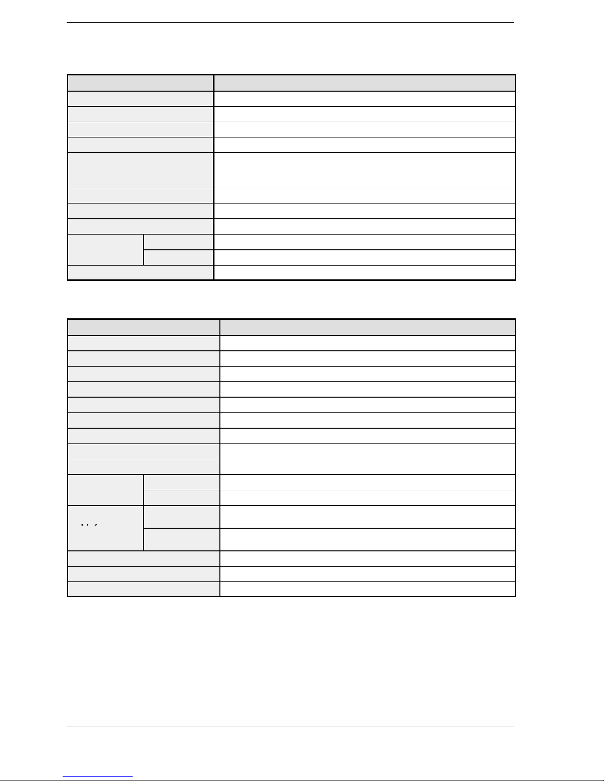
Item Description
Insulation method Optical coupler
Rated input voltage 24 V DC
Operating voltage range 21.6 to 26.4 V DC
Rated input current Approx. 3.5 mA
Input points per common 32 points/common
(Either the positive or negative of input power supply can be connected to
common terminal.)
Min. on voltage/Min. on current 19.2 V DC/3 mA
Max. off voltage/Max. off current 2.4 V DC/1.3 mA
Input impedance Approx. 6.8 kΩ
Response time off → on 0.2 ms or less
on → off 0.3 ms or less
Operating mode indicator LED display
Transistor output specifications
Item Description
Insulation method Optical coupler
Output type Open collector
Rated load voltage 5to24VDC
Operating load voltage range 4.75 to 26.4 V DC
Max. load current 0.1 A
Max. surge current 0.5A
Output points per common 32 points/common
Off state leakage current 100 µA or less
On state voltage drop 0.5 V or less
Response time off → on 0.2 ms or less
on → off 0.5 ms or less
External power
supply for
Voltage 21.6 to 26.4 V DC
supp y
o
driving internal
circuit
Current 15 mA or less
Surge absorber Zener diode
Operating mode indicator LED display
Phase fault protection Thermal protection
Page 43
FPΣ
Expansion
3-8
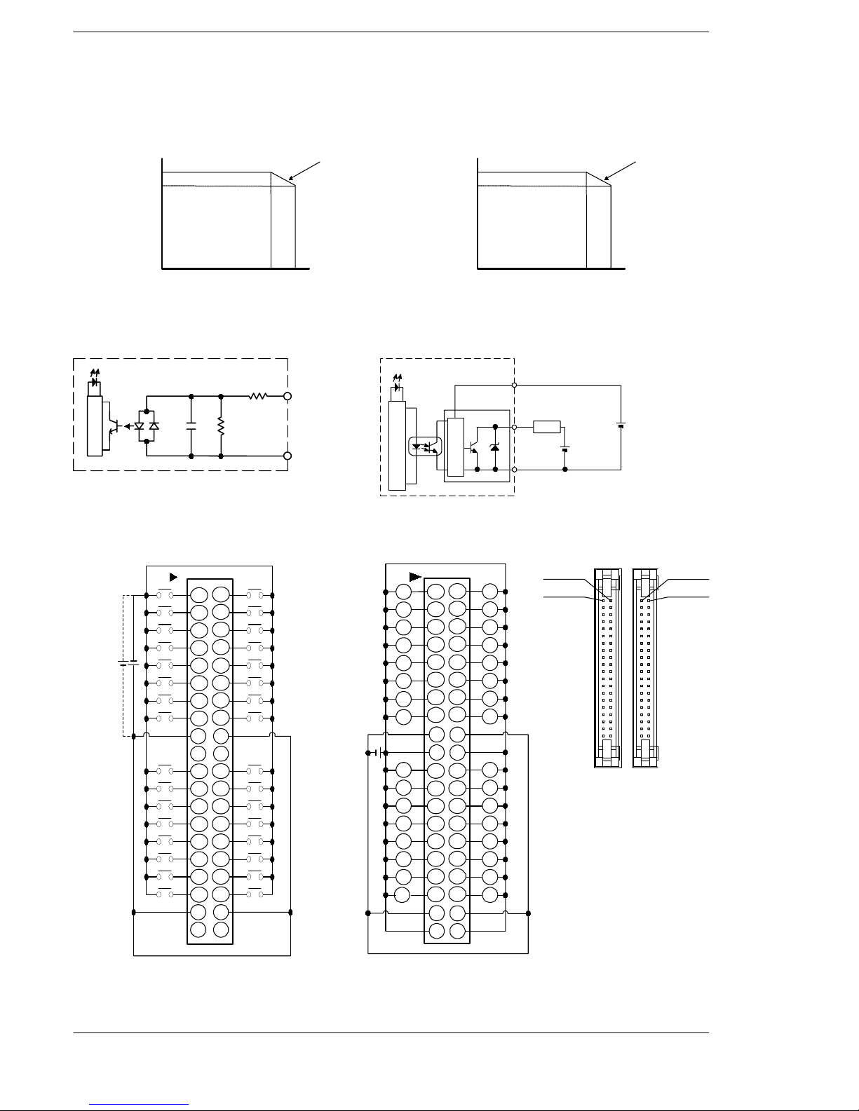
Limitations on number of simultaneous on points
Keep the number of points which are simultaneously on within the following range as
determined by the ambient temperature.
32
52/
118.6
55/
124
29
at 24 VDC
and 26.4
VDC
32
29
Ambienttemperature(°C/°F)
Number of
points per
common
which are simultaneous
on
[Input] [Output]
Ambienttemperature (°C/°F)
Number of
points per
common
which are simultaneous
on
at 24 VDC
and 26.4
VDC
52/
118.6
55/
124
Internal circuit diagram
COM
Xn
Phase fault protection
0V
External power
supply 24 VDC
[Input] [Output]
Internal circuit
Internal circuit
6.8 kΩ
820 Ω
Inside
Output display LED
+
Output terminal
Power
supply for
load 5 to
24 VDC
Load
Output circuit
Terminal layout diagram
5to24VDC
1
AB
1
2 2
3 3
4 4
5 5
6 6
7 7
8 8
9 9
10 10
11 11
12 12
13 13
14 14
15 15
16 16
17 17
18 18
19
—
19
+20+
20
L
L
L
L
L
L
L
L
L
L
L
L
L
L
L
L
L
L
L
L
L
L
L L
L
L
L
L
L
L
L
L
1 1
2 2
3 3
4 4
5 5
6 6
7 7
8 8
COM
99
N.C.
11 11
12 12
13 13
14 14
15
15
16 16
17 17
18 18
COM
19 19
N.C.20N.C.
20
COM
AB
N.C.
COM
24 V DC
10 10
110
111
112
113
114
115
116
117
118
119
11A
11B
11C
11D
11E
11F
100
10D
10C
101
102
103
104
105
106
107
108
109
10A
10B
10F
10E
100
10D
10C
101
102
103
104
105
106
107
108
109
10A
10B
10F
10E
110
111
112
113
114
115
116
117
118
119
11A
11B
11C
11D
11E
11F
X108
X100
Y100
Y108
—
——
++
The COM terminals are connected
internally with thesame connector.
Input connector
(Left side on unit)
Output connector
(Right side on unit)
(Front view of connector)
Although “+” and “-” terminalsare connected
internally with thesame connector, it is recommended that theyalso be connected externally.
Note: The number in the connector are for the first expansion.
Page 44

Chapter 4
I/O
Allocation
4.1 I/O Allocation 4 - 3...................................
Page 45

FPΣI/O Allocation
4-2
Page 46
FPΣ 4.1 I/O Allocation
4-3
4.1 I/O Allocation
This section explains about the I/O allocation of FPΣ.
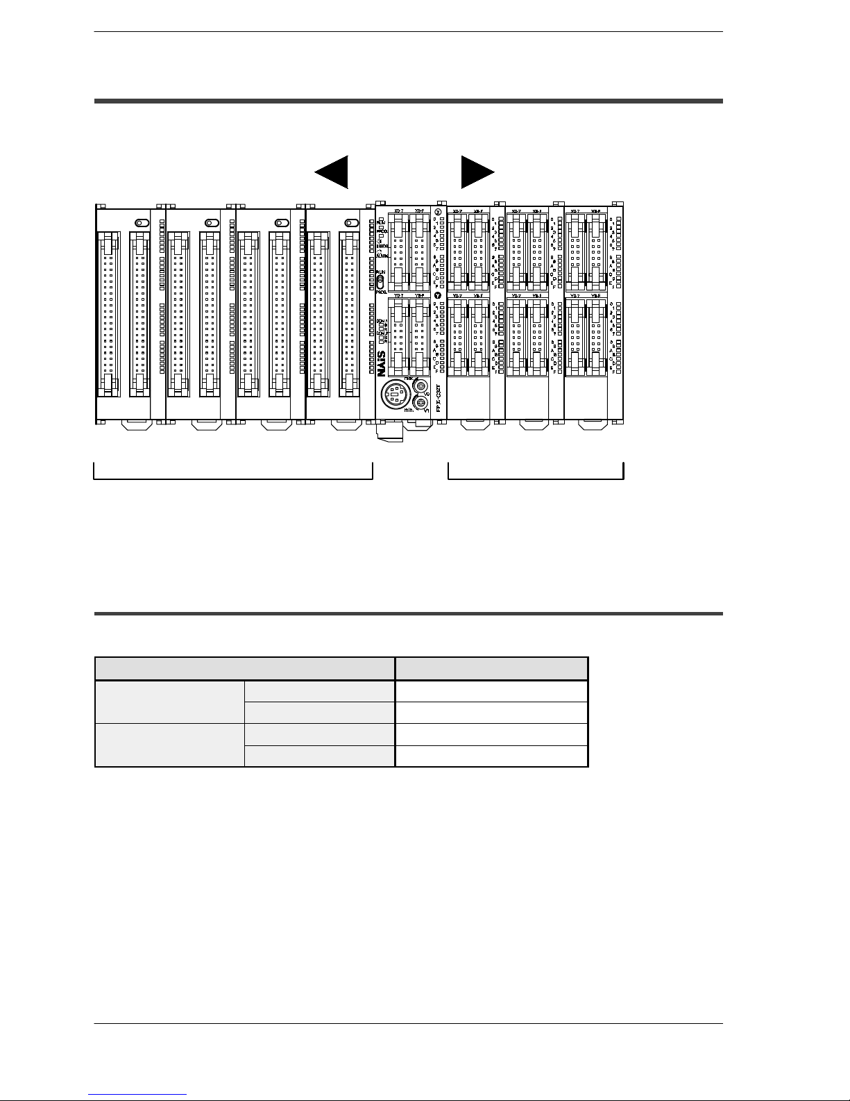
Max. possible expansion is
with a total of three units.
Max. possible expansion is
with a total of four units.
First
expansion
Second
expansion
Third
expansion
First
expansion
Second
expansion
Third
expansion
Fourth
expansion
Control unit FP0 expansion unit sideFPΣ expansion unit side
Figure 22: FPΣ I/O allocation
4.1.1 I/O Number of FPΣ Control Unit
The I/O allocation of FPΣ control unit is fixed.
Type of control unit I/O number
FPG-C32T
Input (16 points) X0 to XF
FPG-C32T2
Output (16 points) Y0 to YF
Input (16 points) X0 to XF
FPG-C24R2
Output (8 points) Y0 to Y7
Page 47
FPΣ
I/O Allocation
4-4
4.1.2 I/O Number of FPΣ Expansion Unit (for left side expansion)
I/O do not need to be set as I/O allocation is performed automatically when an
expansion unit is added.
The I/O allocation of expansion unit is determined by the installation location.
Type of expansion unit
First
expansion
Second
expansion
Third
expansion
Fourth
expansion
Input (32 points) X100 to X11F X180 to X19F X260 to X27F X340 to X35F
XY64D2T
Output (32 points) Y100 to Y11F Y180 to Y19F Y260 to Y27F Y340 to Y35F
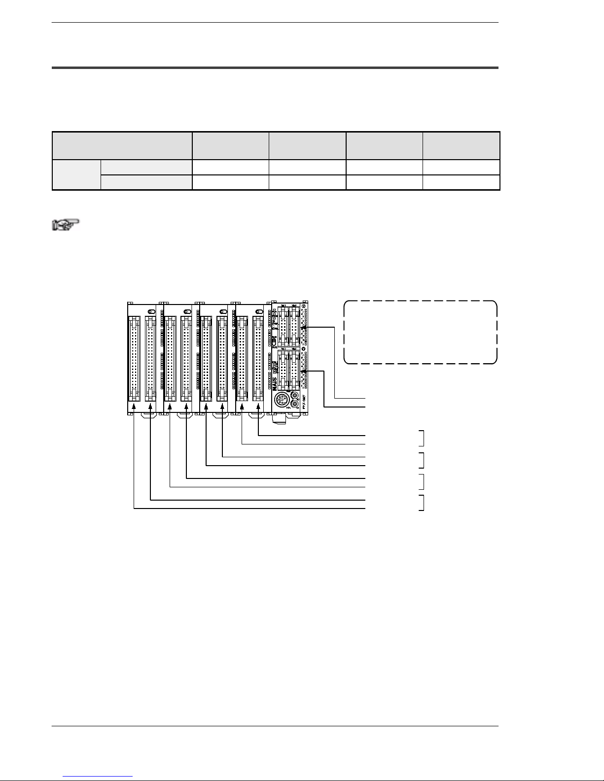
Note
The FPΣexpansion unit nearest the control unit has the lowest
I/O number, so that the unit closest to the control unit is the first
unit, the one next to that the second, and so on. Consequently,
the I/O numbers in the illustration below start with the lowest
number at the right and proceed in sequential order.
FPΣ control unit
Y100 to Y11F
Y180 to Y19F
Y260 to Y27F
Y340 to Y35F
Y0 to YF
X100 to X11F
X180 to X19F
X260 to X27F
X340 to X35F
X0 to XF
FPΣ expansion unit
The I/O numbers indicated below
would be used if the FPG-C32T or
FPG-C32T2 was used as the control
unit, and the XY64D2T was used as
the FPΣ expansion unit.
First expansion
Second expansion
Third expansion
Fourth expansion
Page 48
FPΣ
4.1 I/O Allocation
4-5
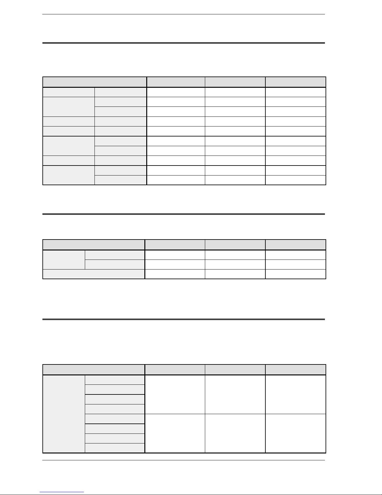
4.1.3 I/O Number of FP0 Expansion Unit (for right side expansion)
I/O do not need to be set as I/O allocation is performed automatically when an
expansion unit is added. The I/O allocation of expansion unit is determined by the
installation location.
Type of expansion unit First expansion Second expansion Third expansion
E8X Input (8 points) X20 to X27 X40 to X47 X60 to X67
Input (4 points) X20 to X23 X40 to X43 X60 to X63
E8R
Output (4 points) Y20 to Y23 Y40 to Y43 Y60 to Y63
E8YR/E8YT/E8YP Output (8 points) Y20 to Y27 Y40 to Y47 Y60 to Y67
E16X Input (16 points) X20 to X2F X40 to X4F X60 to X6F
Input (8 points) X20 to X27 X40 to X47 X60 to X67
E16R/E16T/E16P
Output (8 points) Y20 to Y27 Y40 to Y47 Y60 to Y67
E16YT/E16YP Output(16 points) Y20 to Y2F Y40 to Y4F Y60 to Y6F
Input (16 points) X20 to X2F X40 to X4F X60 to X6F
E32T/E32P
Output (16points) Y20 to Y2F Y40 to Y4F Y60 to Y6F
4.1.4 I/O Number of FP0 Analog I/O Unit (for right side expansion)
The I/O allocation of FP0 analog I/O unit “FP0-A21” is determined by the installation
location.
Unit First expansion Second expansion Third expansion
CH0 (16 points) WX2 (X20 to X2F) WX4 (X40 to X4F) WX6 (X60 to X6F)
I
nput
CH1 (16 points) WX3 (X30 to X3F) WX5 (X50 to X5F) WX7 (X70 to X7F)
Output (16 points) WY2 (Y20 to Y2F) WY4 (Y40 to Y4F) WY6 (Y60 to Y6F)
4.1.5 I/O Number of FP0 A/D Conversion Unit (for right side expansion)
The I/O allocation of FP0 A/D conversion unit “FP0-A80” is determined by the
installation location.
The data for the various channels is converted and loaded with a user program that
includes a switching flag to convert the data.
Unit First expansion Second expansion Third expansion
CH0 (16 points)
CH2 (16 points)
CH4 (16 points)
WX2
(X20toX2F)
WX4(X40toX4F)
WX6
(X60toX6F)
CH6 (16 points)
I
nput
CH1 (16 points)
CH3 (16 points)
CH5 (16 points)
WX3
(X30toX3F)
WX5(X50toX5F)
WX7(X70toX7F)
CH7 (16 points)
Page 49
FPΣ
I/O Allocation
4-6
4.1.6 I/O Number of FP0 I/O Link Unit (for right side expansion)
The I/O allocation of FP0 I/O link unit “FP0-IOL” is determined by the installation
location.
Unit First expansion Second expansion Third expansion
Input (32 points) X20 to X3F X40 to X5F X60 to X7F
Output (32 points) Y20 to Y3F Y40 to Y5F Y60 to Y7F
Specifying X and Y numbers
On the FPΣand the FP0, the same numbers are used for input and output.
Example: The same number “X20 and Y20” can be used for input and output
Tip
Expression of numbers for input/output relays
Since input relay “X” and output relay “Y” are handled in units of 16 points,
they are expressed as a combination of decimal and hexadecimal numbers as
shown below.
I/O number of FPΣand FP0
Decimal
1, 2, 3 ......
Hexadecimal
1, 2, 3 ...... 9, A, B ... F
X
Page 50

Chapter 5
Installation and Wiring
5.1 Installation 5 - 3.....................................
5.2 Wiring of Power Supply 5 - 9..........................
5.3 Wiring of Input and Output 5 - 12.......................
5.4 Wiring of MIL Connector Type 5 - 17...................
5.5 Wiring of Terminal Block Type 5 - 20....................
5.6 Safety Measures 5 - 22...............................
5.7 Backup Battery 5 - 24................................
Page 51

FPΣInstallation and Wiring
5-2
Page 52

FPΣ 5.1 Installation
5-3
5.1 Installation
This section explains installation environment and installation method of FPΣ.
5.1.1 Installation Environment and Space
Avoid installing the unit in the following locations:
- Ambient temperatures outside the range of 0°Cto
55°C/32°F to 131°F
- Ambient humidity outside the range of 30% to 85% RH
- Sudden temperature changes causing condensation
- Inflammable or corrosive gases
- Excessive airborne dust, metal particles or salts
- Benzine, paint thinner, alcohol or other organic solvents or
strong alkaline solutions such as ammonia or caustic soda
- Excessive vibration or shock
- Direct sunlight
- Water or oil in any form including spray or mist
Measures regarding noise:
- Influence from power transmission lines, high voltage
equipment, power cables, power equipment, radio
transmitters, or any other equipment that would generate
high switching surges
- If noise occurs in the power supply line even after the
above countermeasures are taken, it is recommended to
supply power through an insulation transformer, noise
filter, or like.
Page 53
FPΣ
Installation and Wiring
5-4
Measures regarding heat discharge
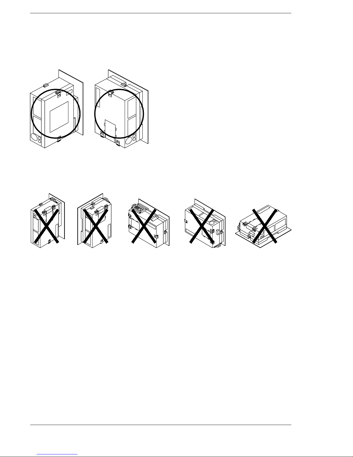
Always install the unit orientated with the tool port facingoutward on the bottom in order
to prevent the generation of heat.
CORRECT
Figure 23: FPΣ Installation-heat discharge
Do not install the FPΣ control unit as shown below.
Upside-down Installation which
blocks the air duct
Installations such that
the input and output
connectors face down
Input and output
connectors on top
Horizontal
installation of the unit
INCORRECT
Figure 24: FPΣ Installation direction
Donotinstalltheunitabovedeviceswhichgenerateheat such as heaters, transformers
or large scale resistors.
Page 54
FPΣ
5.1 Installation
5-5
Installation space
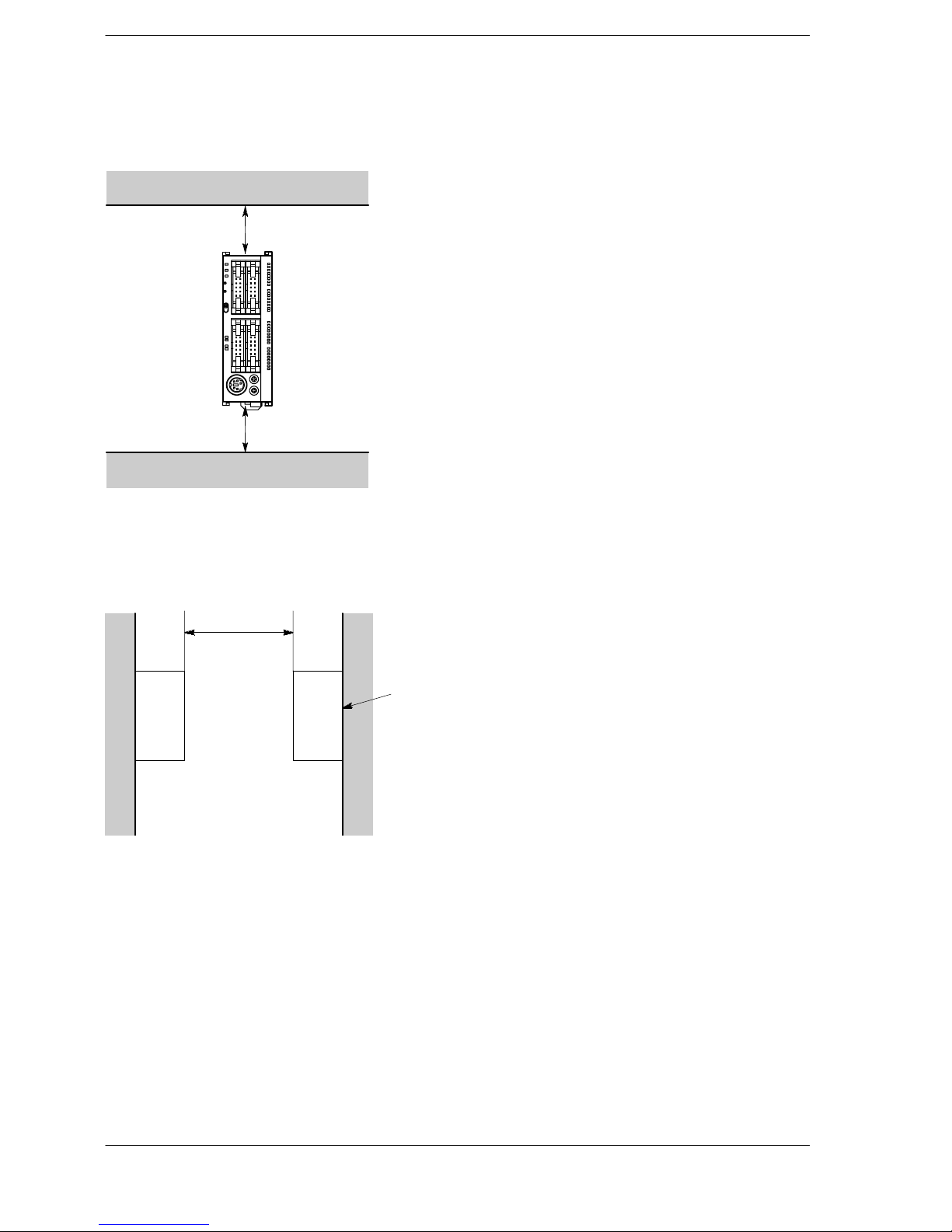
Leave at least 50 mm/1.97 in. of space between the wiring ducts of the unit and other
devices to allow heat radiation and unit replacement.
50 mm/1.97 in.
or more
50 mm/1.97 in.
or more
Figure 25: FPΣ Installation space-1
Maintainaminimumof100mm/3.937in.betweendevicestoavoidadverse affects from
noise and heat when installing a device or panel door to the front of the PLC unit.
100 mm/
3.937 in.
or more
PLC unit
Panel door
Other device
Figure 26: FPΣ Installation space-2
Keep the first 100 mm/3.937 in. from the front surface of the control unit open in order
to allow room for programming tool connections and wiring.
Page 55
FPΣ
Installation and Wiring
5-6
5.1.2 Installation and Removal
Attachment to DIN rail and removal from DIN rail
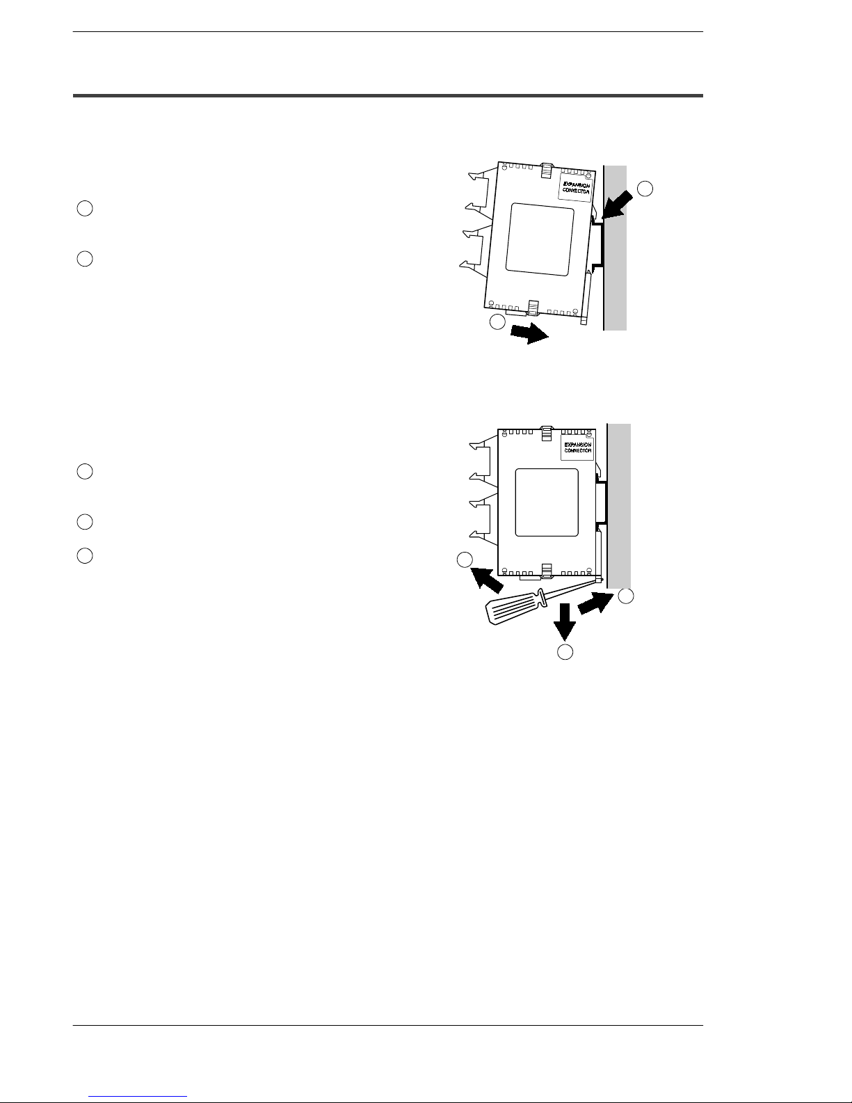
The FPΣ unit enables simple attachment to DIN rails.
Procedure of installation method
1
Fit the upper hook of the unit onto the DIN
rail.
2
Without moving the upper hook, press on the
lower hook to fit the unit into position.
1
2
Figure 27: Installation method
Procedure of removal method
1
Insert a slotted screwdriver into the DIN rail
attachment lever.
2
Pull the attachment lever downwards.
3
Lift up the unit and remove it from the rail.
1
2
3
Figure
28: Removal method
Page 56
FPΣ
5.1 Installation
5-7
Installation using the optional mounting plate
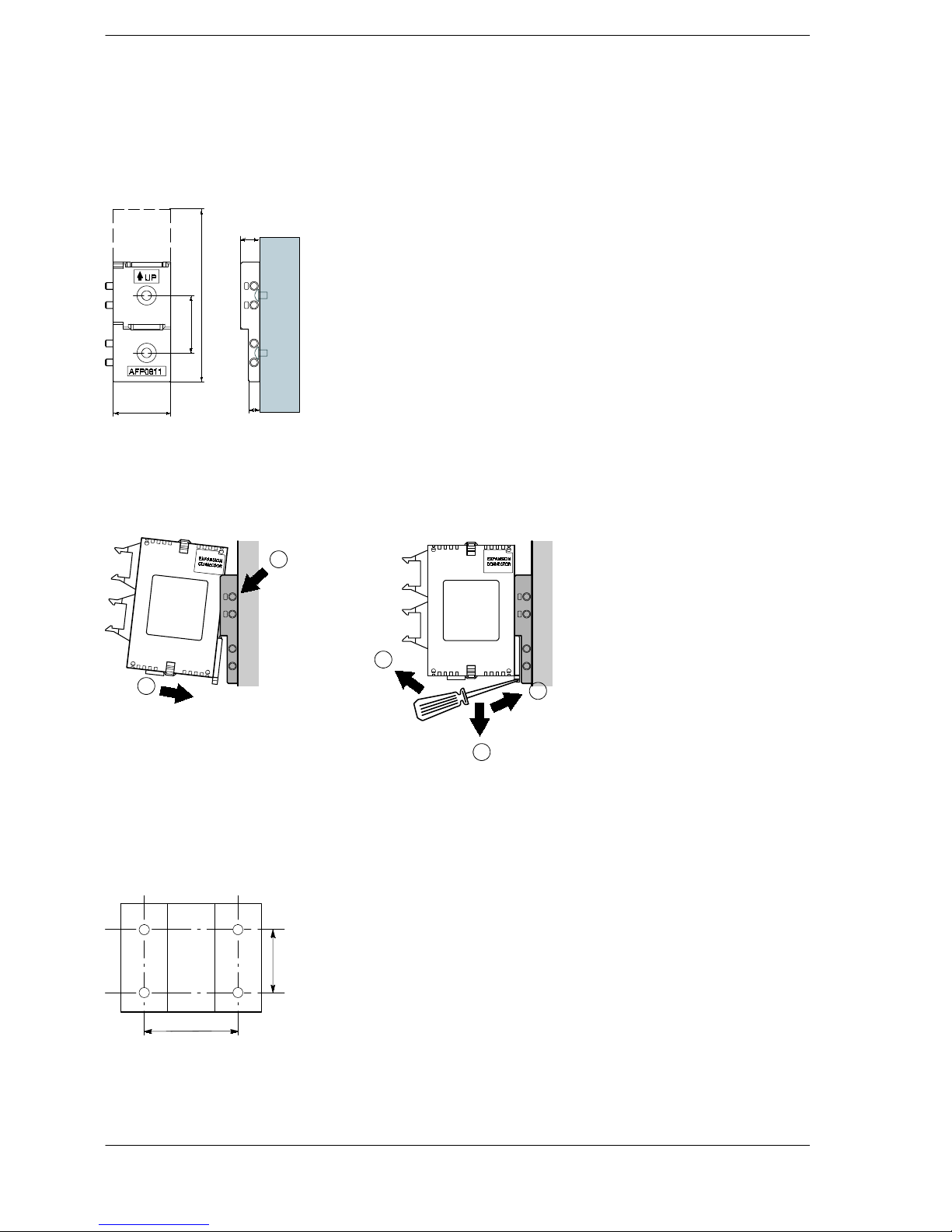
When using the slim 30 type mounting plate (AFP0811)
Use M4 size pan-head screws for attachment of the slim 30 type mounting plate to
mounting panel and install according to the dimensions shown below.
90 mm/3.54 in.
30 mm/
1.18 in.
30 mm/
1.18 in.
6 mm/0.24 in.
10 mm/0.39 in.
Figure 29: FPΣ Installation-optional slim 30 type mounting plate
The rest of the procedure is the same as that for attaching the unit to the DIN rails.
RemovalInstallation
1
4
1
2
3
Figure 30: FPΣ Installation using slim 30 type mounting plate
When using an expansion unit, tighten the screws after joining all of the slim 30 type
mounting plate to be connected. Tighten the screws at each of the four corners.
30.0 mm/1.18 in.
60.0 mm/2.36 in
Example: Two expansion units
Figure 31: FPΣ Installation using two expansion units
Page 57
FPΣ
Installation and Wiring
5-8
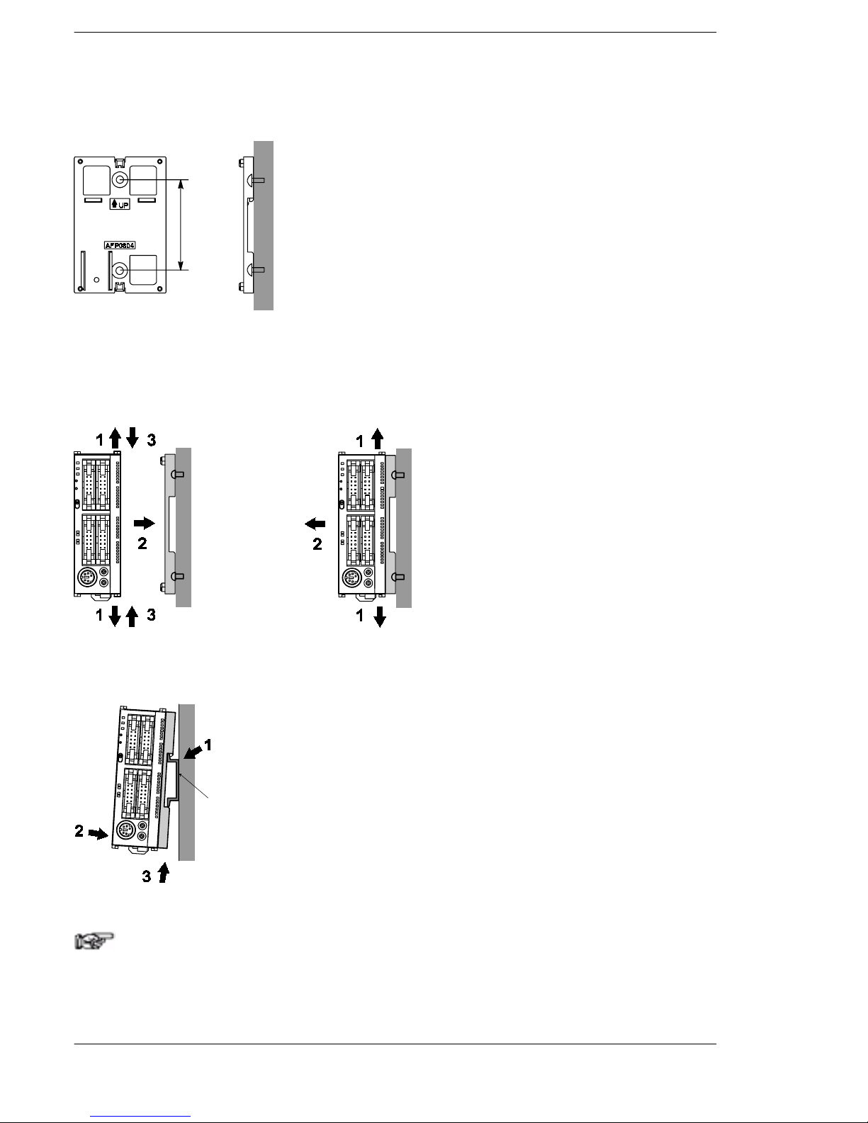
When using the flat type mounting plate (AFP0804)
Use M4 size pan-headscrews for attachment of the flat type mounting plate and install
according to the dimensions shown below.
60.0 mm/
2.36 in.
Figure 32: FPΣ Installation-optional flat type mounting plate
Raise the expansion hooks on the top and bottom of the unit.
Align the expansion hooks with the mounting plate and press the hooks on the top and
bottom.
RemovalInstallation
Figure 33: FPΣ Installation using flat type mounting plate
An unit with an attached flat type mounting plate can also be installed sideways on a
DIN rail.
DIN rail
Figure 34: FPΣ Installation on DIN rail using flat type mounting plate
Note
The flat type mounting plate (AFP0804) should be used only with
the control unit as a stand-alone unit. It should not be used when
the control unit is being used in combination with an FP0
expansion unit or FPΣ expansion unit.
Page 58
FPΣ
5.2 Wiring of Power Supply
5-9
5.2 Wiring of Power Supply
This section explains power supply wiring of FPΣ.
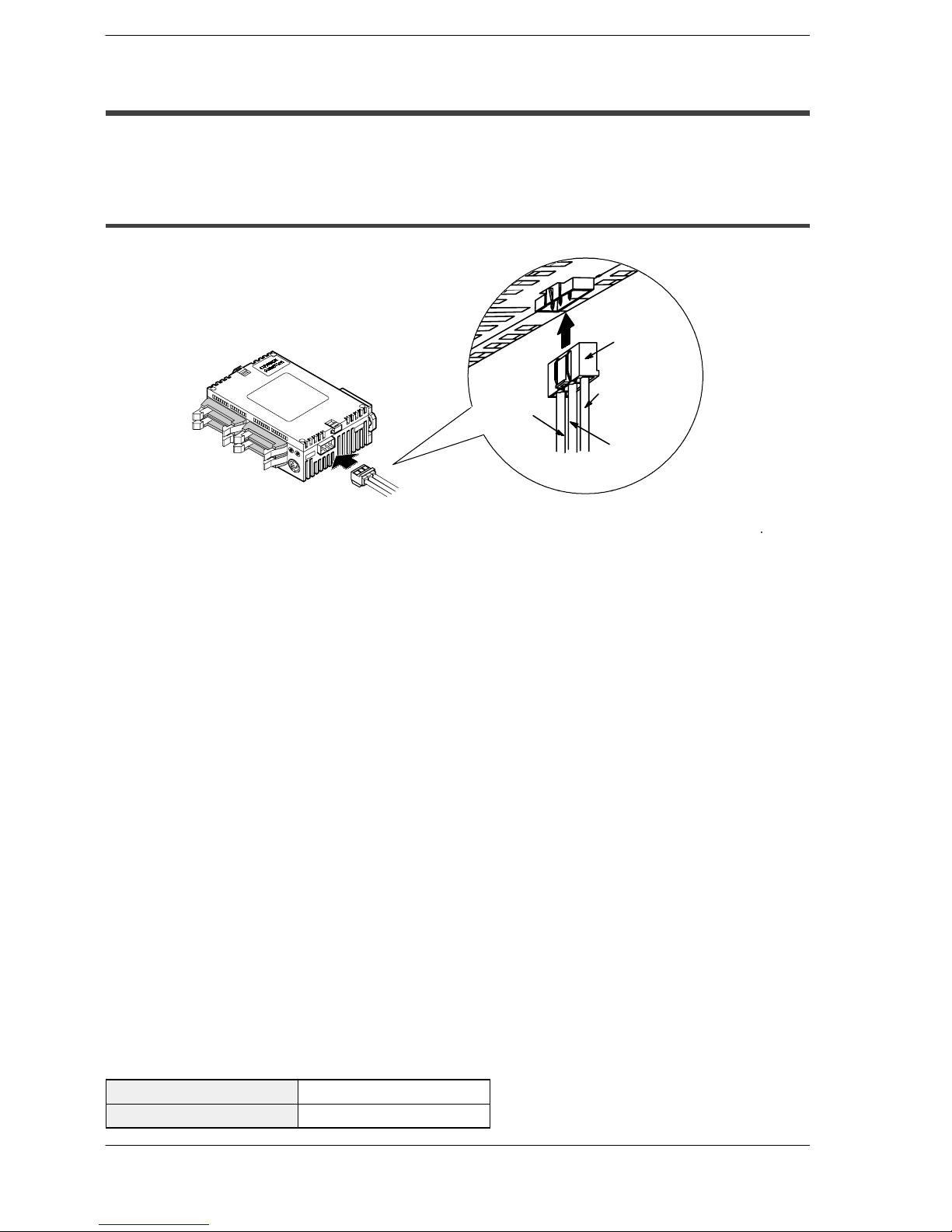
5.2.1 Wiring of Power Supply
Use the power supply cable provided as an accessory
to supply power to the unit.
Power supply
cable
Power
supply cable
(AFP0581)
Green:
Functionearth
Blue: 0 V
Brown:
24 V DC
Figure 35: FPΣ Wiring of power supply
Power supply wiring for the unit
Use the power supply cable (Part No.: AFP0581) that comes with the unit to connect
the power supply.
-Brown: 24 V DC
-Blue: 0 V
-Green: Function earth
Power supply wire
To minimize adverse effects from noise, twist the brown and blue wires of the power
supply cable.
Power supply type
To protect the system against erroneous voltage from the power supply line, use an
insulated power supply with an internal protective circuit.
The regulator on the unit is a non-insulated type.
If using a power supply device without an internal protective circuit, always make sure
power is supplied to the unit through a protective element such as a fuse.
Power supply voltage
Rated voltage
24 V DC
Operating voltage range
21.6 to 26.4 V DC
Page 59
FPΣ
Installation and Wiring
5-10
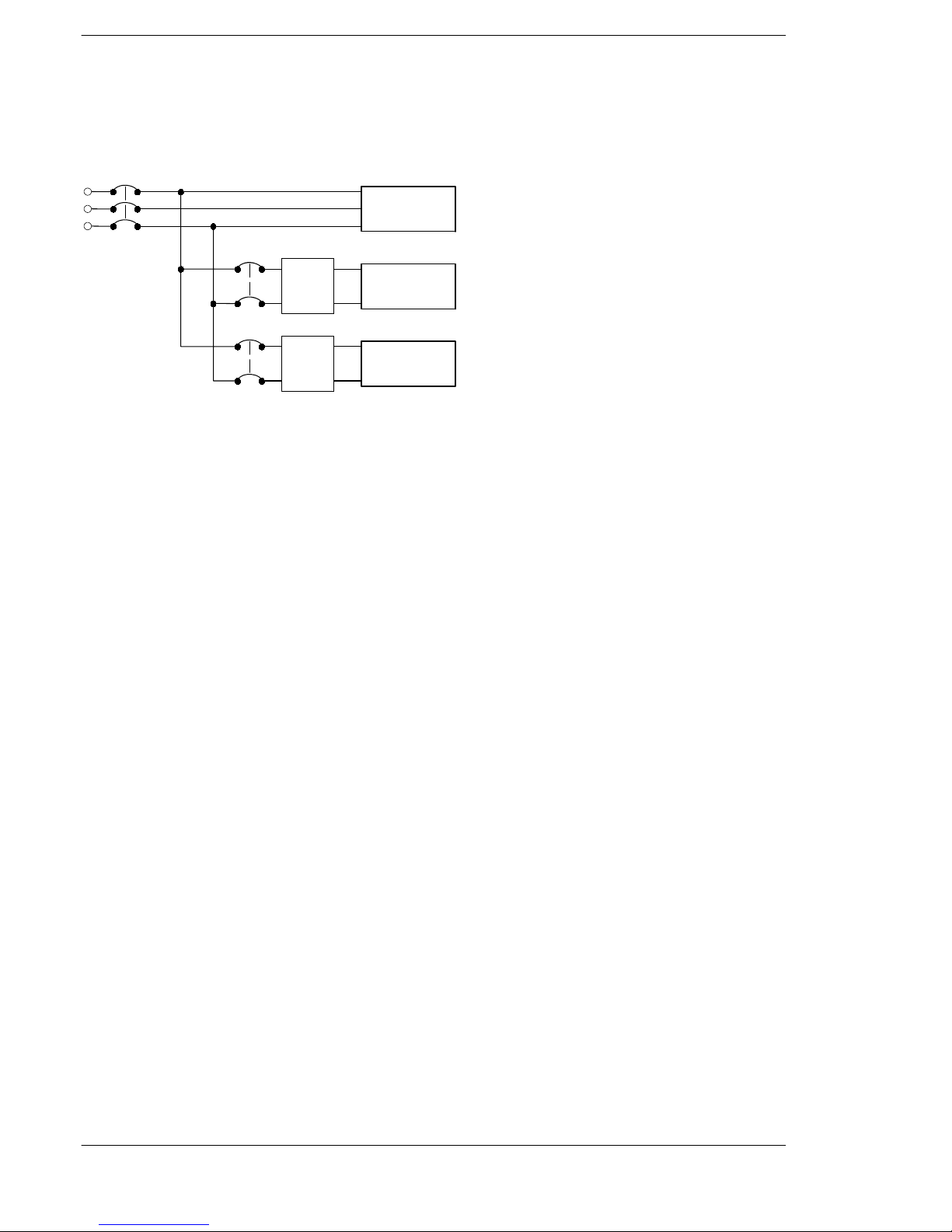
Wiring system
Isolate the wiring systems to the control unit, input/output devices, and mechanical
power apparatus.
Mechanical
power
apparatus
Circuit breaker
Input/Output
devices
Insulated DC
power supply
Control unit
Figure 36: FPΣ Power supply wiring system
Measures regarding power supply sequence (start up sequence)
The power supply sequence should be set up so that power to the control unit is turned
off before the input/output power supplies.
If the input/output power supplies are turned off before the power to the control unit, the
control unit will detect the input fluctuations and may begin an unscheduled operation.
Be sure to supply power to a control unit and an expansion unit from the same power
supply, and turn the power on and off simultaneously for both.
Page 60
FPΣ
5.2 Wiring of Power Supply
5-11
5.2.2 Grounding
Under normal conditions, the inherent noise resistance is sufficient. However, in
situations of excess noise, ground the instrument to increase noise suppression.
For grounding purposes, use wiring with a minimum of 2 mm
2
. The grounding
connection should have a resistance of less than 100 Ω.
The point of grounding should be as close to the PLC unit as possible. The ground wire
should be as short as possible.
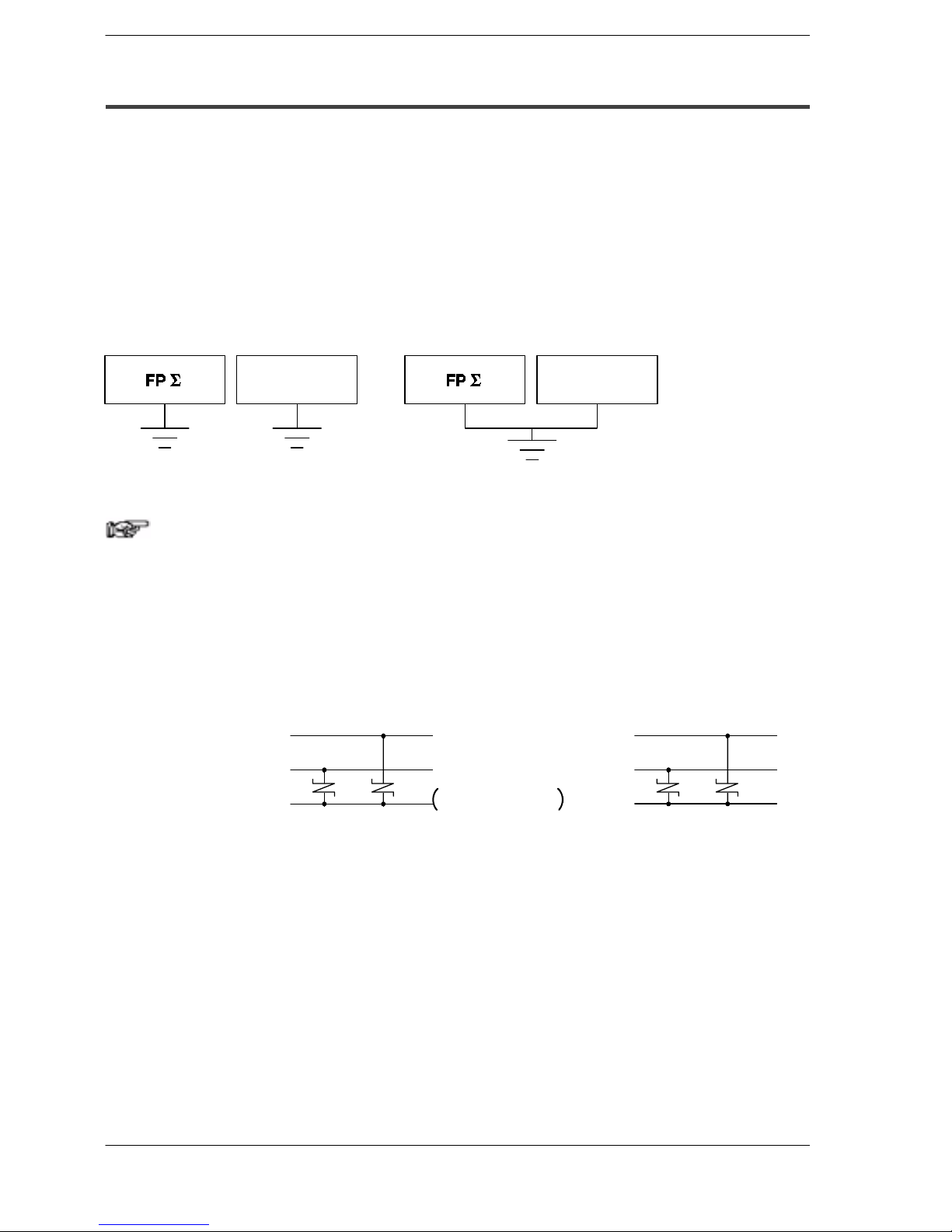
If two devices share a single ground point, it may produce an adverse effect. Always
use an exclusive ground for each device.
Other device
(Inverter etc.)
CORRECT INCORRECT
Other device
(Inverter etc.)
Figure 37: FPΣ Grounding
Note
Depending on the surroundings in which the equipment is used,
grounding may cause problems.
Example:
Since the power supply line of the FPΣ power supply connector
is connected to the function earth through a varistor, if there is
an irregular potential between the power supply line and earth,
the varistor may be shorted.
24 V DC
0V
Function
earth
Varistor
FPΣ power supply line
24 V DC
0V
Function
earth
Varistor
(39 V)
FP0exponsion unit
power supply line
82 V:for C32T, C32T2
56 V:for C24R2
Figure 38: Power supply line of FPΣ and FP0 expansion unit
Page 61
FPΣ
Installation and Wiring
5-12
5.3 Wiring of Input and Output
This section explains input wiring and output wiring of FPΣ.
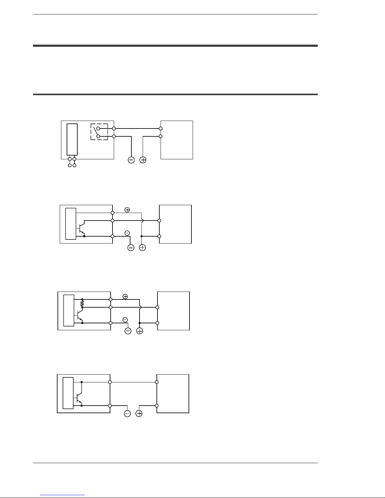
5.3.1 Input Wiring
Connection of photoelectric sensor and proximity sensor
Internal
circuit
Input terminal
COM
Power supply for input
Power supply for sensor
Sensor
Relay
Relay output type
FPΣ
Figure 39: FPΣ Relay output type sensor
COM
Output
Vcc
0V
NPN open collector output type
Internal
circuit
Input terminal
FPΣ
Power supply for input
Sensor
Figure 40: FPΣ NPN open collector output type sensor
Voltage output (Universal output) type
COM
Output
Vcc
0V
Internal
circuit
Input terminal
FPΣ
Power supply for input
Sensor
Figure 41: FPΣ Voltage output (universal output) type sensor
COM
Output
Internal
circuit
Input terminal
Two-wire output type
FPΣ
Power supply for input
Sensor
Figure 42: FPΣ Two-wire output type sensor
Page 62
FPΣ
5.3 Wiring of Input and Output
5-13
Precaution when using LED-equipped lead switch
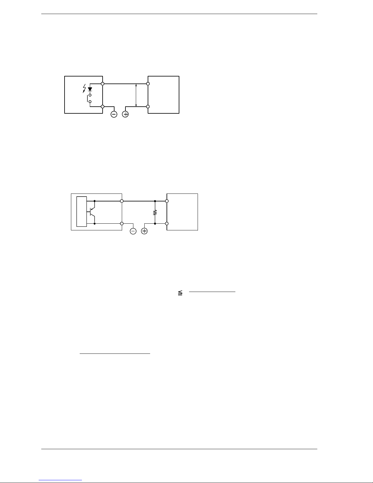
When a LED is connected in series to an input contact such as LED-equipped lead
switch, make sure that the on voltage applied to the PLC input terminal is greater than
19.2 V DC. In particular, take care when connecting a number of switches in series.
LEDequipped
lead
switch COM
24 V
19.2 V
or more
LED
contact
Input terminal
FPΣ
Figure 43: FPΣ Precaution when using LED-equipped lead switch
Precaution when using two-wire type sensor
If the input of PLC does not turn off because of leakage current from the two-wire
type sensor “photoelectric sensor or proximity sensor”, the use of a bleeder resistor
is recommended, as shown below.
Two-wire
type sensor
Bleeder
resistor
COM
Input terminal
Internal
circuit
R
FPΣ
Figure 44: FPΣ Precaution when using two-wire type sensor
The off voltage of the input is 2.4 V, therefore, select the value of bleeder resistor “R” so that
the voltage between the COM terminal and the input terminal will be less than 2.4 V.
The input impedance is 5.6 kΩ.(I: Sensor’s leakage current (mA))
The resistance R of the bleeder resistor is: R
The formula is based on an input impedance of 5.6 kΩ. The input impedance varies depending on the input terminal number .
The wattage W of the resistor is:
In the actual selection, use a value that is 3 to 5 times the value of W.
13.44
(Power supply voltage)
2
R
(kΩ)
5.6 x I –2.4
W=
Page 63
FPΣ
Installation and Wiring
5-14
Precaution when using LED-equipped limit switch
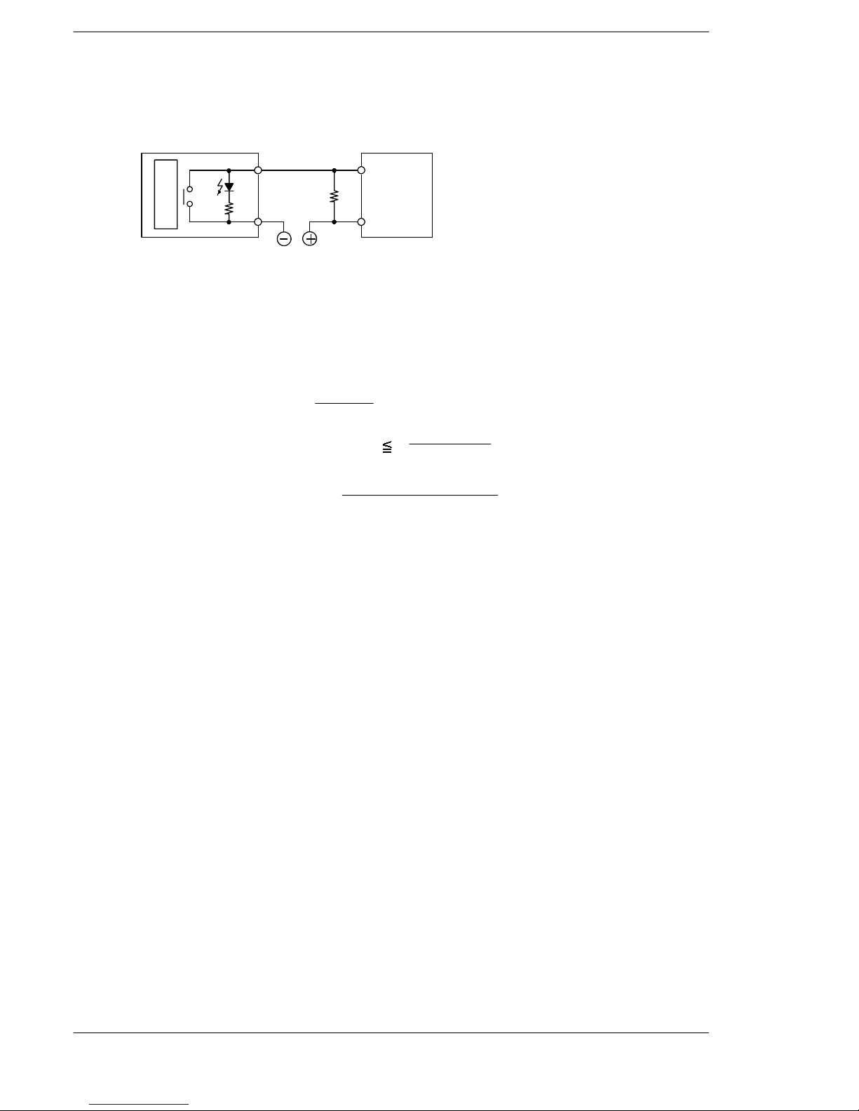
If the input of PLC does not turn off because of the leakage current from the LEDequipped limit switch, the use of a bleeder resistor is recommended, as shown below.
r: Internal resistor of limit switch (kΩ)
LEDequipped
limit switch
Bleeder
resistor
COM
Input terminal
Internal
circuit
R
Power supply for input
r
FPΣ
Figure 45: FPΣ Precaution when using LED-equipped limit switch
The off voltage of input is 2.4 V, therefore when the power supply voltage is 24 V, select the
bleeder resistor “R” so that
the current will be greater than I =
The resistance R of the bleeder resistor is: R
The wattage W of the resistor is: W =
In the actual selection, use a value that is 3 to 5 times the value of W.
13.44
5.6 x I - 2.4
(kΩ)
24 - 2.4
r
(Power supply voltage)
2
R
Page 64
FPΣ
5.3 Wiring of Input and Output
5-15
5.3.2 Output Wiring
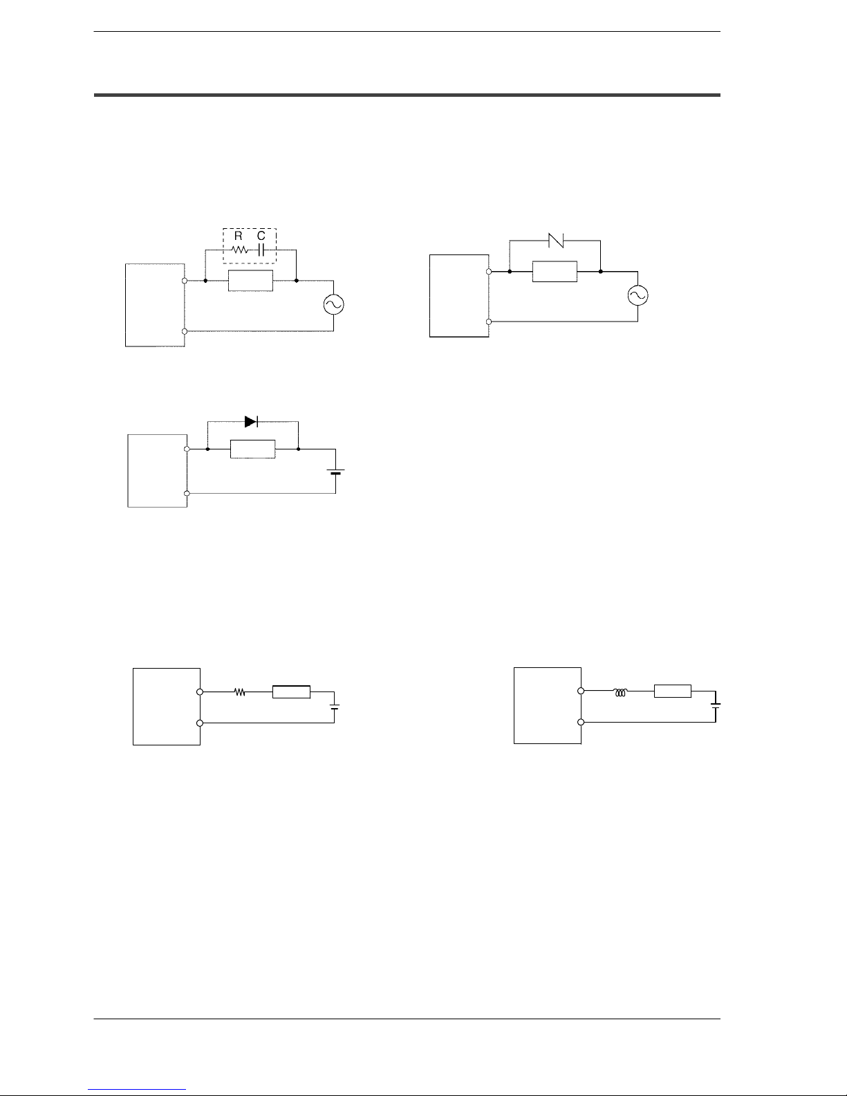
Protective circuit for inductive loads
With an inductive load, a protective circuit should be installed in parallel with the load.
When switching DC inductive loads with relay output type, be sure to connect a diode
across the ends of the load.
When using an AC inductive load
COM
Output
terminal
Varistor
FPΣ
Load
When using a DC inductive load
FPΣ
Reverse voltage (VR): 3 times the load voltage
Average rectified forward current (I
0
): Load current or more
Diode:
COM
Output
terminal
Diode
Load
Precautions when using capacitive loads
When connecting loads with large in-rush currents, to minimize their effect, connect a
protection circuit as shown below.
Load
Resistor
Output
terminal
COM
Load
Inductor
Output
terminal
COM
FP
Σ
FP
Σ
Figure 46: FPΣ Precautions when using capacitive loads
About the short-circuit protective circuit
To prevent the output circuit from being damaged by a short-circuit or other electrical
problems on the output side, a transistor with short-circuit protection is provided.
Example of surge absorber: R: 50 Ω, C: 0.47 μF
FPΣ
COM
Output
terminal
Surge absorver
Load
Page 65

FPΣ
Installation and Wiring
5-16
5.3.3 Precautions Regarding Input and Output Wirings
Be sure to select the thickness (dia.) of the input and output wires while taking into
consideration the required current capacity.
Arrange the wiring so that the input and output wiring are separated, and these wirings
are separated from the power wiring, as much as possible. Do not route them through
the same duct or wrap them up together.
Separate the input/output wires from the power and high voltage wires by at least
100 mm/3.937 in.
Page 66
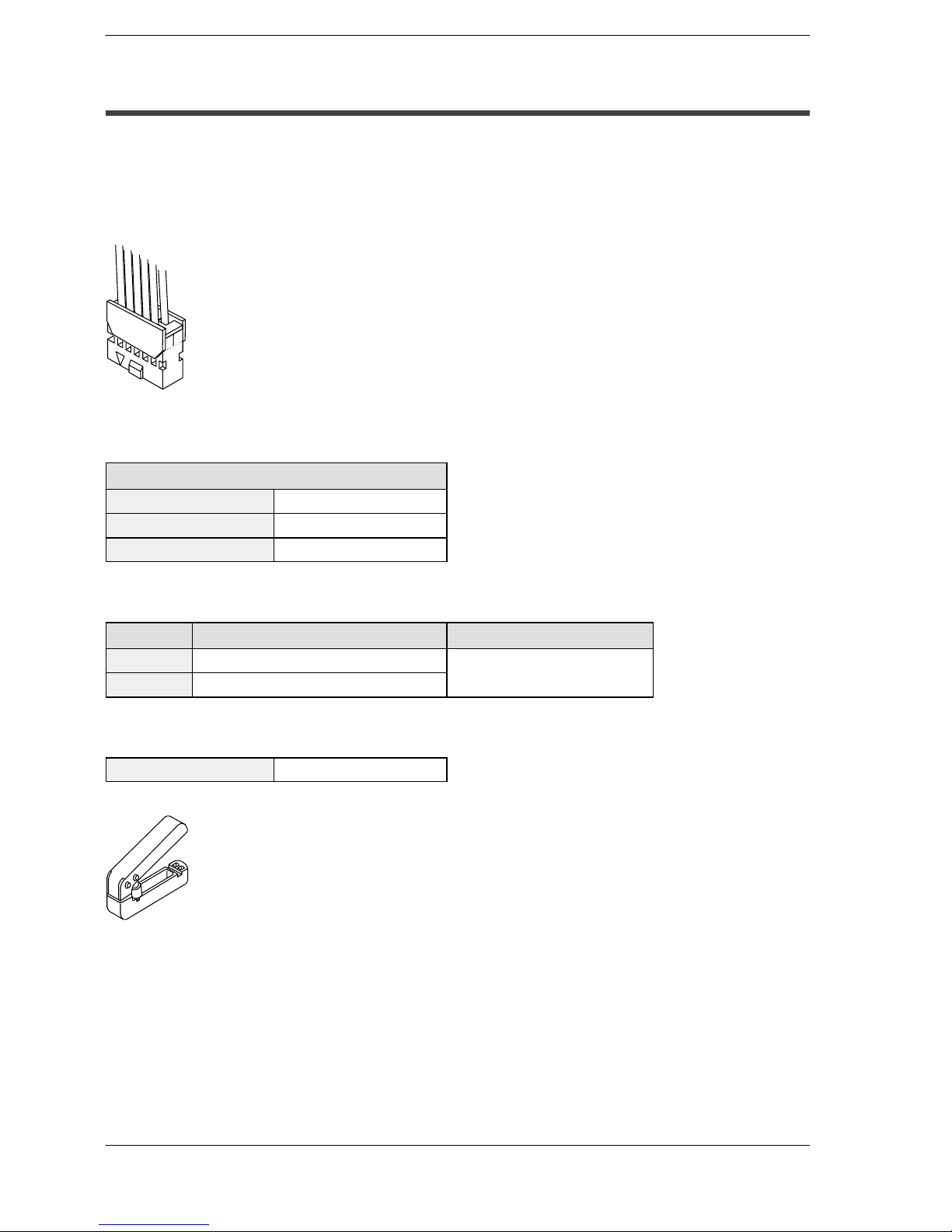
FPΣ
5.4 Wiring of MIL Connector Type
5-17
5.4 Wiring of MIL Connector Type
Supplied connector and Suitable wires
The connector “housings, semi-cover andwelders” listed below come supplied with the
FPΣcontrol unit.
Use the suitable wires given below. Also, use the required pressure
connection tools for connecting the wires.
Figure 47: FPΣ Supplied MIL connector
Supplied connector (AFP0807)
Type and Product No.
Housing 10-pin type only
Semi-cover AXW61001
Welder (contact) AXW7221
Suitable wires
Size Conductor cross-sectional area Insulation thickness
AWG#22 0.3 mm
2
dia. 1.5 to dia. 1.1
AWG#24 0.2 mm
2
Pressure connection tool
Product No. AXY52000
Figure 48: FPΣ Pressure connection tool
Page 67
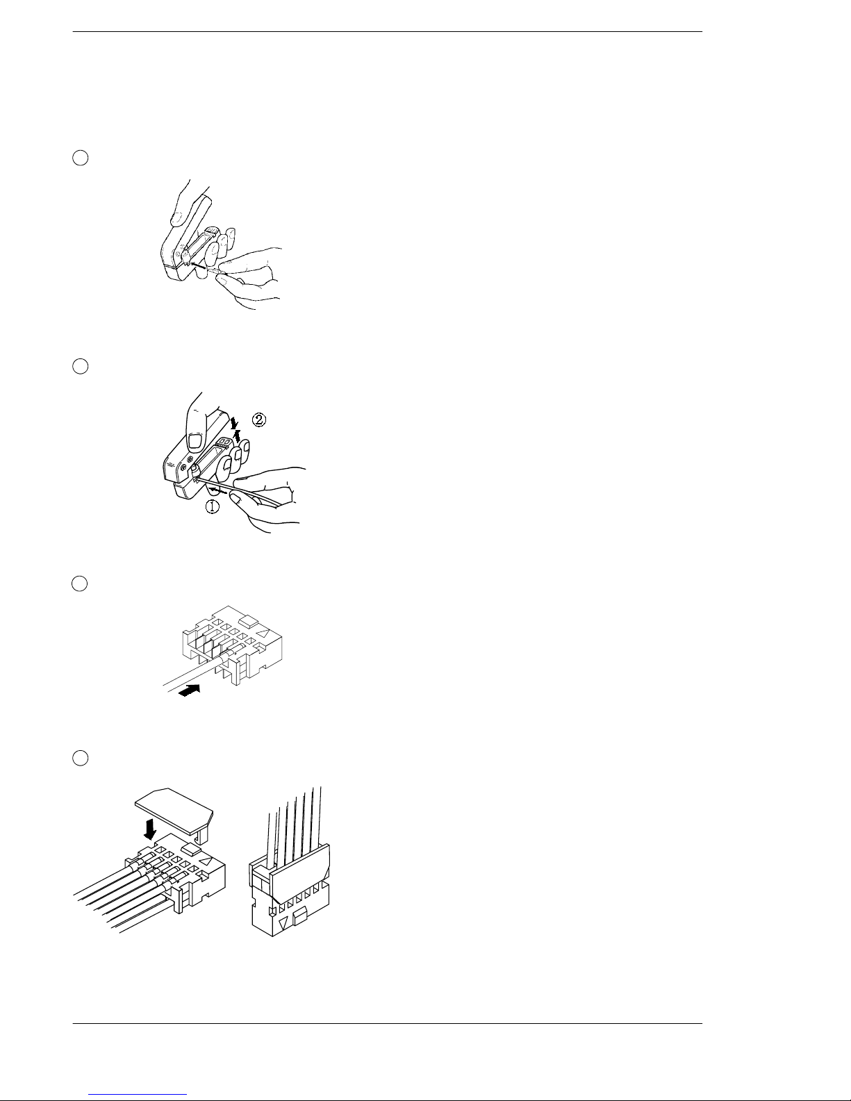
FPΣ
Installation and Wiring
5-18
Procedure of assembly (Wiring method)
The wire end can be directly crimped without removing the wire’s insulation, saving
labor.
1
Bend the welder (contact) back from the carrier, and set it in the pressure connection
tool.
Figure 49: FPΣ MIL connector assembly procedure-1
2
Insert the wire without removing its insulation until it stops, and lightly grip the tool.
Figure 50: FPΣ MIL connector assembly procedure-2
3
After press-fitting the wire, insert it into the housing.
Figure 51: FPΣ MIL connector assembly procedure-3
4
When all wires has been inserted, fit the semi-cover into place.
Figure 52: FPΣ MIL connector assembly procedure-4
Page 68
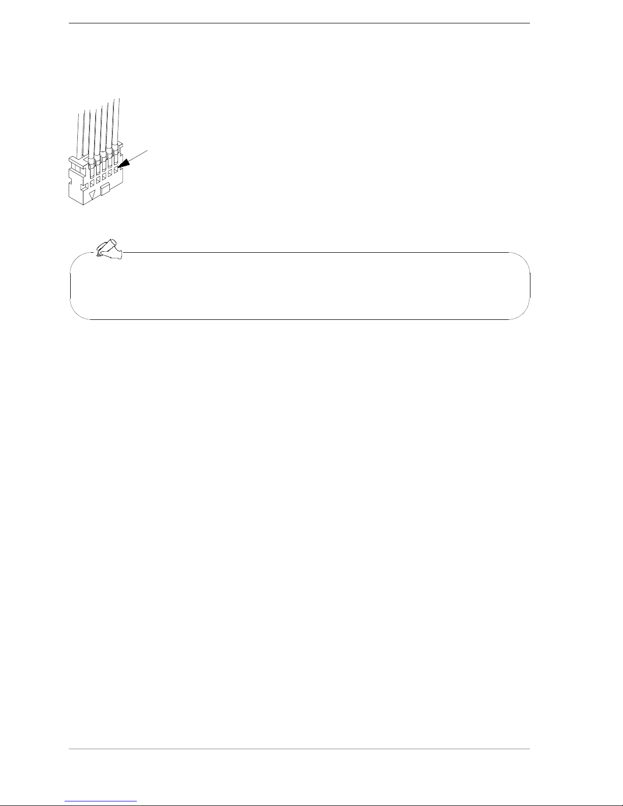
FPΣ
5.4 Wiring of MIL Connector Type
5-19
Press the housing against the pressure connection tool so that
the contact puller pin comes in contact with this section.
If there is a wiring mistake or the cable is incorrectly pressure-connected, the contact
puller pin provided with the fitting can be used to remove the contact.
Figure 53: FPΣ MIL connector-rewiring
If using a MIL connector for flat cables, specify the product no. AXM110915.
Tip
Page 69
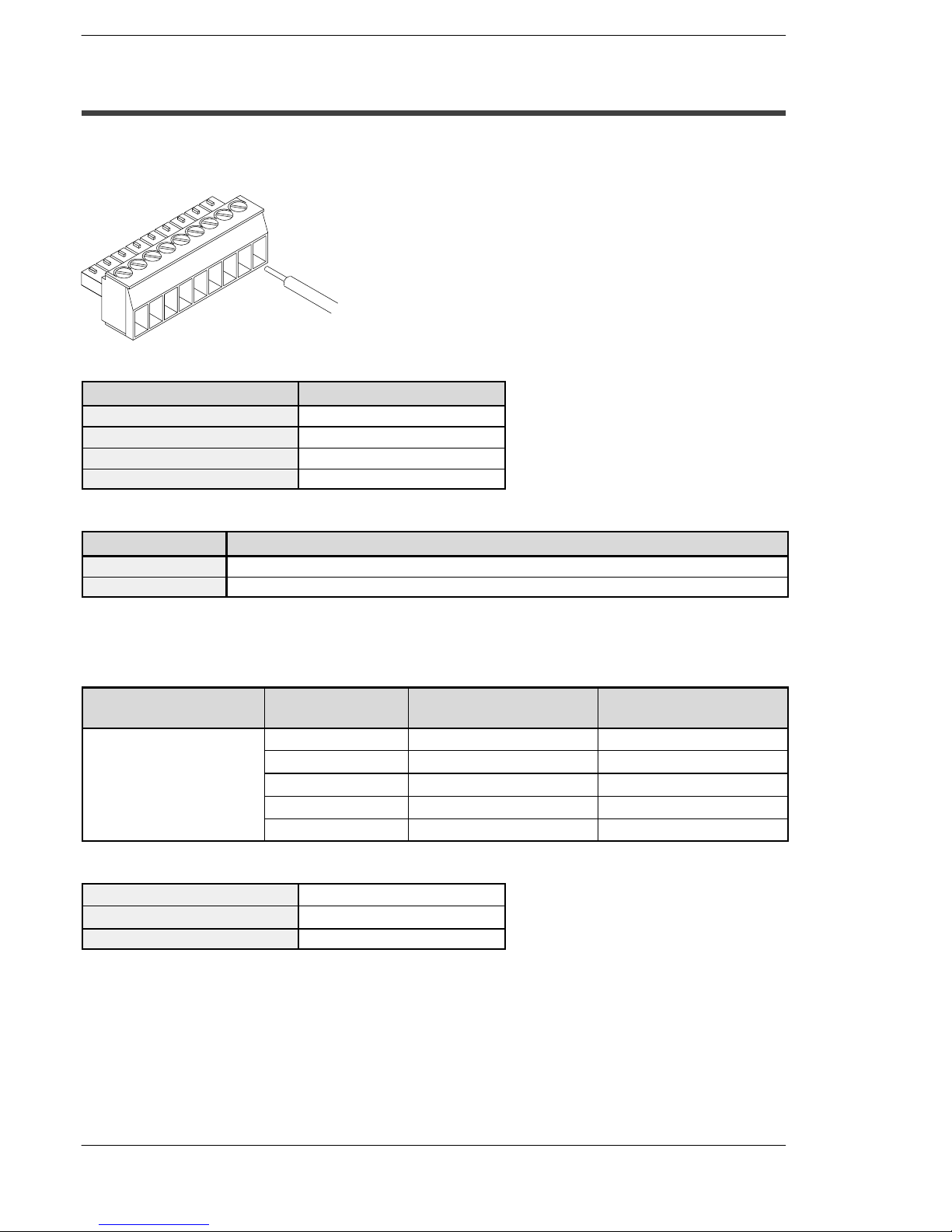
FPΣ
Installation and Wiring
5-20
5.5 Wiring of Terminal Block Type
A screw-down connection type for terminal block is used. The suitable wires are given
below.
Terminal block socket
Item Description
Number of pin 9 pins
Manufacturer Phoenix Contact Co.
Model MC1,5/9-ST-3,5
Product number 1840434
Suitable wires
Size Nominal cross-sectional area
AWG #22 0.3 mm
2
AWG #24 to 16 0.2 to 1.25 mm
2
Pole terminal with a compatible insulation sleeve
If a pole terminal is being used, the following models are marketed by Phoenix Contact
Co.
Manufacturer
Cross-sectional
area (mm
2
)
Size Part No.
Phoenix Contact Co.
0.25
A
WG #24
AI 0,25 - 6YE
0.50
AWG #20
AI 0,5 - 6WH
0.75
AWG #18
AI 0,75 - 6GY
1.00
AWG #18
AI 1 - 6RD
0.5 x 2
AWG #20 (for 2 pcs.)
AI - TWIN 2 x 0.5 - 8WH
Pressure welding tool for pole terminals
Manufacturer
Phoenix Contact Co.
Part No.
CRIMPFOX UD6
Product number
12 04 43 6
Whentighteningtheterminalsoftheterminalblock,useascrewdriver(PhoenixContact
Co., Product No. 1205037) with a blade size of 0.4 × 2.5. Thetightening torque should
be 0.22 to 0.25 N⋅m (2.3 to 2.5 kgf⋅cm) or less.
Page 70
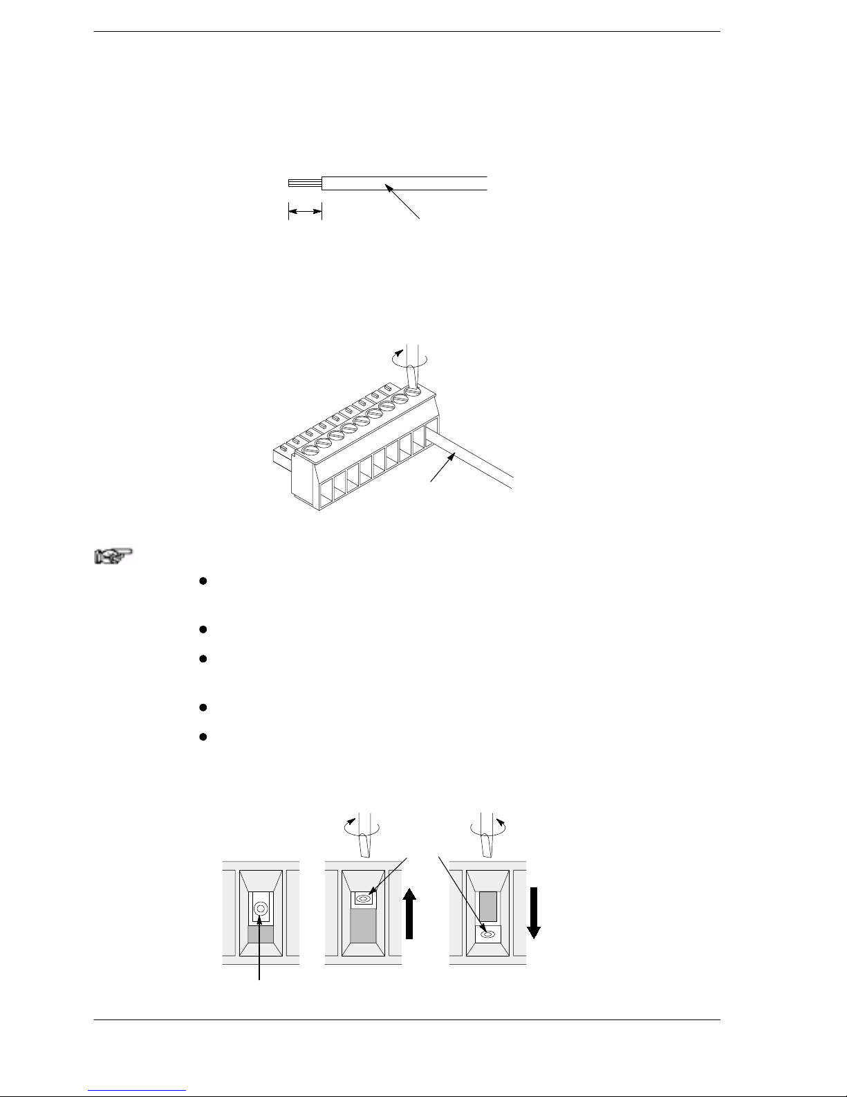
FPΣ
5.5 Wiring of Terminal Block Type
5-21
Wiring method
Procedure:
1. Remove a portion of the wire’s insulation.
7 mm/0.276 in.
Suitable wire
2. Insert the wire into the terminal block until it contacts the
back of the block socket, and then tighten the screw
clockwise to fix the wire in place.
Clockwise
Wire
Notes
When removing the wire’s insulation, be careful not to scratch
the core wire.
Do not twist the wires to connect them.
Do not solder the wires to connect them. The solder may
break due to vibration.
After wiring, make sure stress is not applied to the wire.
In the terminal block socket construction, if the wire closes
upon counter-clockwise rotation, the connection is faulty.
Disconnect the wire, check the terminal hole, and then
re-connect the wire.
Clockwise Counter
clockwise
Wire
Wire
CORRECT INCORRECT
Page 71

FPΣ
Installation and Wiring
5-22
5.6 Safety Measures
This section explains the safety measures, momentary power failures and protection
of power supply and output.
5.6.1 Safety Measures
Precautions regarding system design
In certain applications, malfunction may occur for the following reasons:
Power on timing differences between the PLC system and
input/output or mechanical power apparatus
Responce time lag when a momentary power drop occurs
Abnormality in the PLC unit, external power supply, or other
devices
In order to prevent a malfunction resulting in system shutdown choose the adequates
safety measures listed in the following:
Interlock circuit
When a motor clockwise/counter-clockwise operation iscontrolled, provide an interlock
circuit externally.
Emergency stop circuit
Add an emergency stop circuit externally to controlled devices in order to prevent a
system shutdown or an irreparable accident when malfunction occurs.
Start up sequence
The PLC should be operated after all of the outside devices are energized. To keep this
sequence, the following measures are recommended:
Turn on the PLC with the mode selector set to the PROG. mode,
and then switch to the RUN mode.
Program the PLC so as to disregard the inputs and outputs until
the outside devices are energized
Note
When stopping the operation of the PLC also, have the
input/output devices turned off after the PLC has stopped
operating.
Grounding
When installing the PLC next to devices that generate high voltages from switching,
such as inverters, do not ground them together. Use an exclusive ground for each
device.
Page 72

FPΣ
5.6 Safety Measures
5-23
5.6.2 Momentary Power Failures
Operation of momentary power failures
If the duration of the power failure is less than 4 ms, the FPΣ continues to operate. If
the power is off for 4 ms or longer, operation changes depending on the combination
of units, the power supply voltage, and other factors. (In some cases, operation may
be the same as that for a power supply reset.)
5.6.3 Protection of Power Supply and Output Sections
Power supply
An insulated power supply withan internal protective circuit should be used. The power
supply for the control unit operation is a non-insulated circuit, so if an incorrect voltage
is directly applied, the internal circuit may be damaged or destroyed. If using a power
supply without a protective circuit, power should be supplied through a protective
element such as a fuse.
Protection of output
If current exceeding the rated control capacity is being supplied in the form of a motor
lock current or a coil shorting in an electromagnetic device, a protective element such
as a fuse should be attached externally.
Page 73
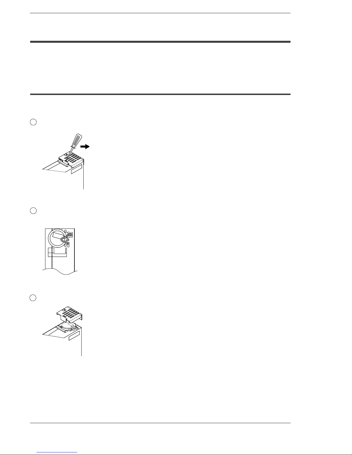
FPΣ
Installation and Wiring
5-24
5.7 Backup Battery
This section explains installation, lifetime of backup battery and battery alarm error
function setting.
5.7.1 Installation of Backup Battery
Installing a backup battery in the FPΣ makes it possible to access clock/calendar
functions for use, in addition to backing up data registers and other data.
1
Using a screwdriver or similar tool, open the battery cover.
Figure 54: FPΣ Backup battery installation procedure-1
2
Connect the connector, and place the battery so that the battery terminal fits between the
two tabs.
Figure 55: FPΣ Backup battery installation procedure-2
3
Insert the battery cover from above.
Figure 56: FPΣ Backup battery installation procedure-3
Page 74
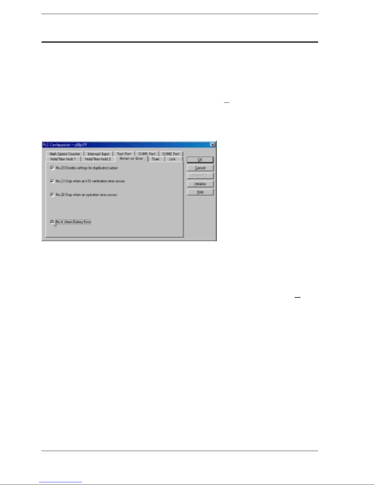
FPΣ
5.7 Backup Battery
5-25
5.7.2 System Register Setting
Setting the battery error alarm
In the system register default settings, “No. 4 Alarm Battery Error” is set to “Off”. When
using the battery, set system register No. 4 of the control unit so that the battery error
alarm is turned on.
Setting procedure using FPWIN GR
1. Select “PLC Configuration” on the “O
ption” menu, and click
on “Action on Error” tab.
2. Turn on “No. 4 Alarm Battery Error” check box.
PLC Configuration setting dialog box
Figure 57: FPWIN GR - PLC Configuration setting dialog box
Specifying the hold area
In order to use backup functions such as data registers, settings must be entered for
system registers Nos. 6 to 12.
For hold area setting using FPWIN GR, select “PLC Configuration” on the “O
ption”
menu, and click on “Hold/Non-hold 1” and “Hold/Non-hold 2”.
Page 75
FPΣ
Installation and Wiring
5-26
5.7.3 Lifetime of Backup Battery
The life of the backup battery will eventually expire and therefore it is important to
replaceit with a new battery periodically. Refer to the table below for a guide as to when
to replace the battery.
Item Description
Battery lifetime 220 days or more (typical lifetime in actual use: approx. 840 days
at 25 °C/70 °F) (Suggested replacement interval: 1 year)
(Valuewhen no power at all is supplied)
Maintenance battery
Name Part No.
Battery for FPΣ AFPG804
Notes
If system register “No. 4 Alarm Battery Error” is set to “ON”,
special internal relays R9005 and R9006 will go on if the
battery voltage drops, and the ERROR/ALARM LED will flash.
The battery remains effective for about a week after the alarm
is issued, but in some cases the problem is not detected
immediately. The battery should be replaced as soon as
possible, without turning off the power supply.
When replacing the battery, connect the new battery within 20
seconds of removing the old one.
Page 76

Chapter 6
High-speed Counter and Pulse Output
Functions
6.1 Overview of Each Functions 6-3......................
6.2 Function Specifications and Restricted Items 6-5.......
6.3 High-speed Counter Function 6-10...................
6.4 Pulse Output Function 6-20..........................
6.5 PWM Output Function 6-56..........................
Page 77

FPΣHigh-speed Counter and Pulse Output Functions
6-2
Page 78
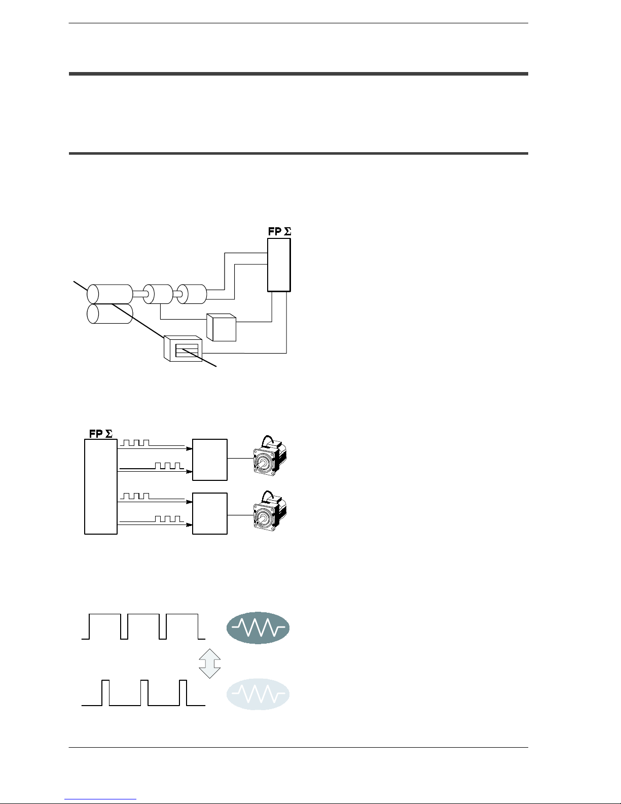
FPΣ 6.1 Overview of Each Functions
6-3
6.1 Overview of Each Functions
This section explains about the functions that use built-in high-speed counter of FPΣ.
6.1.1 Three Functions that Use Built-in High-speed Counter
Functions that use built-in high-speed counter
There are three functions available when using the high-speed counter built into the
FPΣ.
Roller
Cutter
Tape, lead wire
Cutter blade control signal
STARTSTOP
signal
Inverter
Motor Encoder
Encoder output is input to
the high-speed counter
High-speed counter function
The high-speed counter function counts
external inputs such as those from sensors
or encoders. When the count reaches the
target value, this function turns on/off the
desired output.
Figure 58: FPΣ High-speed counter function
Y0
Y1
Y3
Y4
Pulse output function
Combined with a commercially available
motor driver, the function enables positioning control. With the exclusive instruction,
you can perform trapezoidal control, home
return, and JOG operation.
Pulse output CW
Pulse output CW
PulseoutputCCW
PulseoutputCCW
Motor
driver 1
Motor
driver 2
Stepping motor
Servo motor
Stepping motor
Servo motor
Figure 59: FPΣ Pulse output function
PWM output function
By using the exclusive instruction, the
PWM output function enables a pulse
output of the desired duty ratio.
When you increase the pulse width...
When you decrease it...
Heatingincreases.
Heating decreases.
Figure 60: FPΣ PWM output function
Page 79
FPΣ
High-speed Counter and Pulse Output Functions
6-4
6.1.2 Performance of Built-in High-speed Counter
Number of channel
There are four channels for the built-in high-speed counter.
The channel number allocated for the high-speed counter will change depending on
the function being used.
Counting range
K-2,147,483,648 to K2,147,483,647 (Coded 32-bit binary)
The built-in high-speed counter is a ring counter. Consequently, if the counted
value exceeds the maximum value, it returns to the minimum value. Similarly, if the
counted value drops below the minimum value, it goes back to the maximum value
and continues counting from there.
Max. value =
Min. value =
+ 2,147,483,647
+ 2,147,483,646
+ 2,147,483,645
- 2,147,483,646
- 2,147,483,647
- 2,147,483,648
Figure 61: Counting range of high-speed counter
Note
When the linear interpolation instruction F175 or the circular
interpolation instruction F176 is used, the value for the target
value or the amount of travel should be set so that it is within the
range indicated below.
-8,388,608 to +8,388,607 (24-bit binary, with sign)
The F175 and F176 instructions can be used only with the C32T2
control unit.
Page 80
FPΣ
6.2 Function Specifications and Restricted Items
6-5
6.2 Function Specifications and Restricted Items
This section contains specifications and restriction of functions.
6.2.1 Table of Specifications
High-speed counter function specifications
Input/output contact
number being used
Built-in
high-
Memory area being used Performance
specifications
Related
instruc-
On/off
output
Count
input
mode
Input
contact
number
(value
in parenthesis is
reset
input)
*Note 1
speed
counter
channel no.
Control
flag
Elapsed
value
area
Target
value
area
Minimum
input
pulse
width
*Note 2
Maximum
counting
speed
tions
Specify
the
desired
output
Addition
input,
Subtraction
X0
(X2)
CH0 R903A DT90044
to
DT90045
DT90046
to
DT90047
10 µs · Using
one channel:
Max. 50 kHz
(×1-channel)
p
from
Y0 to Y7
using
instruction
input
X1
(X2)
CH1 R903B DT90048
to
DT90049
DT90050
to
DT90051
(
)
· Using
two channels:
Max. 30 kHz
(×2-channel)
tio
n
X3
(X5)
CH2 R903C DT90200
to
DT90201
DT90202
to
DT90203
· Using
threechannels:
Max. 20 kHz
(×3-channel)
F0 (MV),
F1
(DMV),
X4
(X5)
CH3 R903D DT90204
to
DT90205
DT90206
to
DT90207
· Using
four channels:
Max. 20 kHz
(×4-channel)
()
F166
(HC1S),
F167
(HC1R)
Specify
the
desired
output
2-phase
input,
One input,
X0
X1
(X2)
CH0 R903A DT90044
to
DT90045
DT90046
to
DT90047
25 µs · Using
one channel:
Max. 20 kHz
(×1-channel)
f
rom
Y0 to Y7
using
instruction
D
i
rection distinction
X3
X4
(X5)
CH2 R903C DT90200
to
DT90201
DT90202
to
DT90203
· Using
two channels:
Max. 15 kHz
(×2-channel)
Notes
1) Reset input X2 can be set to either CH0 or CH1. Reset input X5
can be set to either CH2 or CH3.
2) For information on min. input pulse width, see page 6 - 12.
Page 81
FPΣ
High-speed Counter and Pulse Output Functions
6-6
Pulse output function specifications
Built-in-Input/output contact number being used Memory area being used Maximum
Related
-
high
speed
counter
channel
no.
CW or
Pulse
output
CCW
or sign
output
Deviation
counter
clear
output
Home
input
Near
home
input
Control
flag
Elapsed
value
area
Target
value
area
outpu
t
frequency
inst
ruc-
tions
CH0
Y0 Y1 Y2 X2 DT90052
<bit4>
R903A DT90044
to
DT90045
DT90046
to
DT90047
·Using
one channel:
Max. 100 kHz
(×1-channel)
· Using
two channels:
Max. 60 kHz
F0 (MV),
F1
(DMV),
F171
(SPDH),
F172
(PLSH)
CH2
Y3 Y4 Y5 X5 DT90052
<bit4>
R903C DT90200
to
DT90201
DT90202
to
DT90203
Max.60kHz
(×2-channel)
· Using linear
interpolation:
Max. 100 kHz
· Using circular
interpolation:
Max. 20 kHz
F174
(SP0H)
F175
(SPSH)
F176
(SPCH)
Note
The linear and circular interpolation control functions can be
used with the C32T2 control unit only.
PWM output function specifications
Built-in
high-speed
Output contact
number being used
Memory area
being used
Output frequency
(duty)
Related
instructions
counter
channel no.
Control flag
CH0 Y0
R903A · When the resolution
is 1000,
1.5 Hz to 12.5 kHz
(0.0 to 99.9 %)
F0 (MV),
CH2 Y3
R903C
(
)
· When the resolution
is 100,
15.6 kHz to 41.7 kHz
(0 to 99 %)
F1(DMV)
,
F173 (PWMH)
Page 82
FPΣ
6.2 Function Specifications and Restricted Items
6-7
6.2.2 Function being Used and Restrictions
Channel
The same channel cannot be used by more than one function.
Function
being used
Channel High-speed counter function
(Addition input and Subtraction input)
High-speed counter
function
(Two-phase input,
One input, and Direction distinction)
CH0 CH1 CH2 CH3 CH0 CH2
Pulse output
CH0 N/A A A A N/A A
function
CH2 A A N/A A A N/A
A: Available N/A: Not Available
Restrictions on I/O allocations
The inputs and outputs allocated to the various functions listed in the table in the
previous section “6.2.1” cannot be allocated to more than one function.
Except for the examples noted below, inputs and outputs that have been allocated to
the various functions cannot be allocated as normal inputs and outputs.
Cases in which inputs and outputs can be used as exceptions
Example 1:
If no reset input is used in the high-speed counter function,
X2 and X5 are allocated as normal inputs.
Example 2:
If no output is used to clear the differential counter in the
pulse output function, Y2 and Y5 are allocated as normal
outputs.
Restrictions on the execution of related instructions (F166 to F176)
When any of the instructions related to the high-speed counter “
F166toF176”
are
executed,thecontrolflag(specialinternalrelay: R903A to R903D) corresponding tothe
used channel turns on.
Please be aware that the control flag is in progress may change while a scan is being
carried out. To prevent this, an internal relay should be substituted at the beginning of
the program.
When the flag for a channel turns on, another instruction cannot be executed using that
same channel.
Page 83

FPΣ
High-speed Counter and Pulse Output Functions
6-8
Restrictions for maximum counting speed and pulse output frequency
The counting speed when using the high-speed counter function will differ depending
on the counting mode as shown in the table on page 6 - 5.
Example 1:
While in the decremental input mode and using the two
channels CH0 and CH1, CH0 and CH1 can be used up to 30 kHz.
Example 2:
While in the two-phase input mode and using the two channels
CH0 and CH2, CH0 and CH2 can be used up to 15 kHz.
The maximum output frequency when using the pulse output function will differ
depending on the number of channel being used as shown in the table on page 6 - 6.
Example 1:
When using only one channel, CH0, up to 100 kHz can be used.
Example 2:
When using two channels, CH0 and CH2, up to 60 kHz may be
used for each channel.
Example 3:
When linear interpolation control is being carried out on CH0
and CH2, a composite speed of up to 100 kHz may be used for
the pulse output function. When circular interpolation control is
being carried out, the maximum composite speed that may be
used is 20 kHz.
If using both the pulse output function and the high-speed counter function, the
following combinations result.
Example 1:
When using one pulse output channel with a maximum output of
60 kHz, the maximum counting speed of the high-speed counter
is 20 kHz in the single-phase and three channels mode.
Example 2:
When using one pulse output channel with a maximum output of
60 kHz, the maximum counting speed of the high-speed counter
is 15 kHz in the two-phase and one channel mode.
Note
The linear and circular interpolation control functions can be
used with the C32T2 control unit only.
Page 84
FPΣ
6.2 Function Specifications and Restricted Items
6-9
6.2.3 Booting Time
The booting time is the time from when the instruction is executed, to the time that the
pulse is actually output.
Type of instruction Booting time
Pulse output instruction F171 (SPDH)
trapezoidal control/home return
If CW/CCW is set : approx.200µs (with 30 steps setting)
: approx.400µs (with 60 steps setting)
If Pulse/Sign is set : approx.500µs (with 30 steps setting) (*)
: approx.700µs (with 60 steps setting) (*)
Pulse output instruction F172 (PLSH)
JOG operation
If CW/CCW is set: approx. 20 µs
If Pulse/Sign is set: approx. 320 µs(*)
Pulse output instruction F174 (SP0H) Data
table control
If CW/CCW is set: approx. 30 µs
If Pulse/Sign is set: approx. 330 µs(*)
PWM output instruction F173 (PWMH)
Approx. 30 µs
(*) If Pulse/Sign is set, a waitingtime (approx. 300µs) is included from the time that the
Sign output goes on until the pulse output instruction can be executed.
Page 85
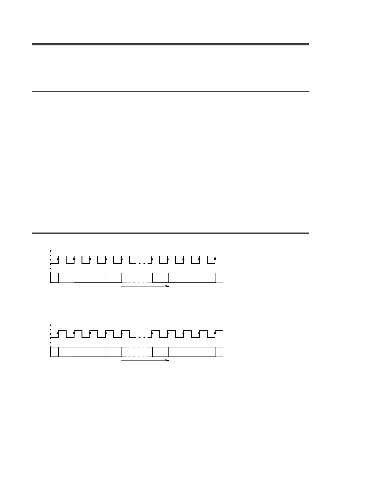
FPΣ
High-speed Counter and Pulse Output Functions
6-10
6.3 High-speed Counter Function
This section explains about the high-speed counter function of FPΣ.
6.3.1 Overview of High-speed Counter Function
High-speed counter function
The high-speedcounter function counts the input signals, and when the count reaches
the target value, turns on and off the desired output.
To turn on an output when the target value is matched, use the target value match on
instructionF166 (HC1S). To turn off an output, use the target valuematch off instruction
F167 (HC1R).
Preset the output to be turned on and off with the SET/RET instruction.
Setting the system register
In order to use the high-speed counter function, it is necessary to set system register
Nos. 400 and 401.
6.3.2 Types of Input Modes
X0
on
off
1 2 3 4 n-3 n-2 n-1 n0
Count
Addition input mode
Figure 62: FPΣ High-speed counter function - addition input mode
X0
on
off
n-1 n-2 n-3 n-4 3 2 1 0n
Count
Subtraction input mode
Figure 63: FPΣ High-speed counter function - subtraction input mode
Page 86
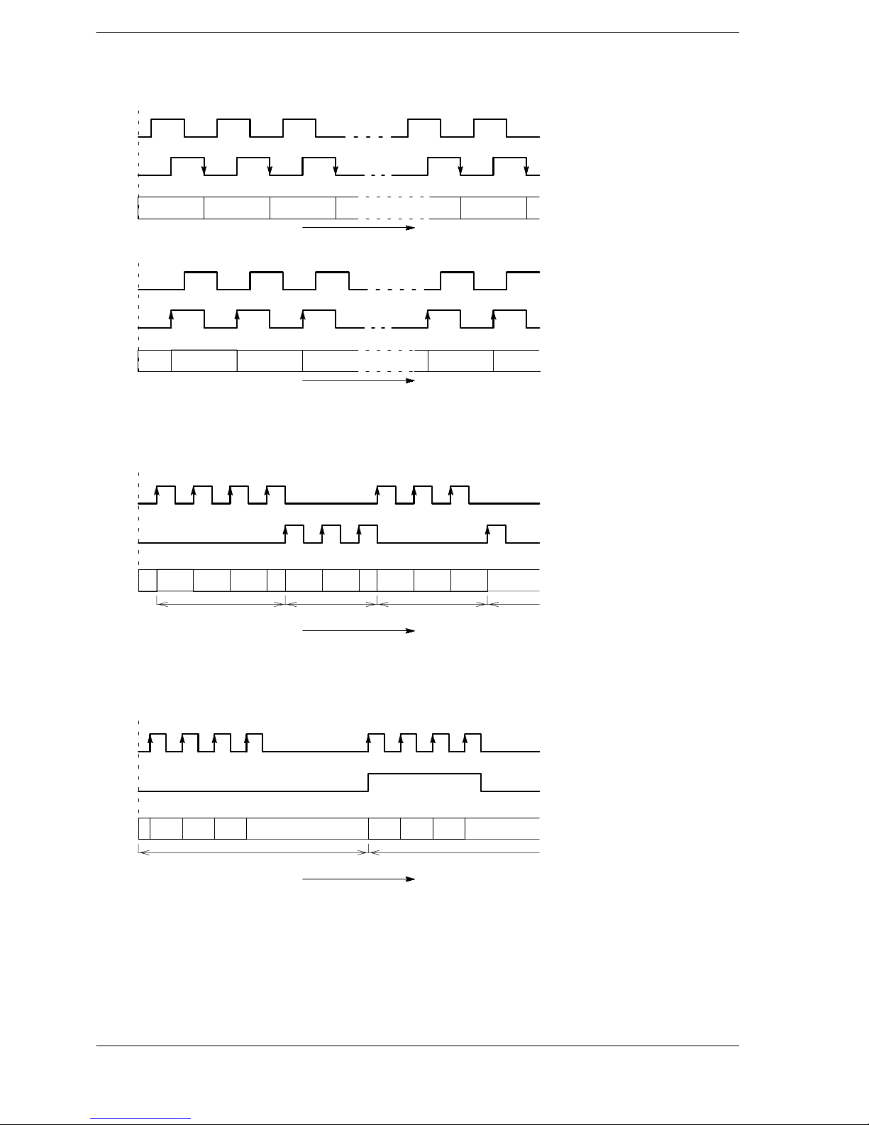
FPΣ
6.3 High-speed Counter Function
6-11
X0
X1
on
off
on
off
n-1
(Incremental input: CW)
0 1 2 nCount
Two-phase input mode (Phase difference input mode)
X0
X1
on
off
on
off
n-3
(Decremental input: CCW)
n-1n n-2 21Count
Figure 64: FPΣ High-speed counter function - two-phase input mode
X0
on
off
1 2 3 2 3 430 3 24 1
on
off
X1
Increasing
Decreasing Increasing Decreasing
Count
One input mode (Addition and subtraction input mode)
Figure 65: FPΣ High-speed counter function - One input mode
3210
X0
on
off
2 04 3
on
off
X1
Increasing
Decreasing
1
Count
Direction distinction mode
Figure 66: FPΣ High-speed counter function - direction distinction mode
Page 87
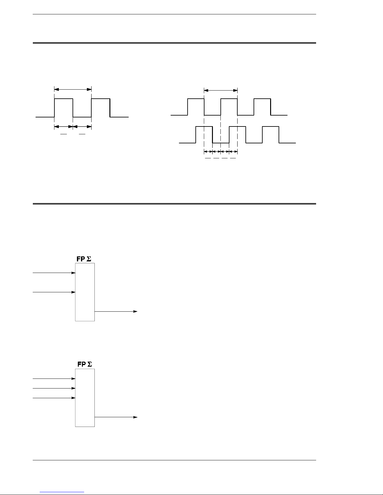
FPΣ
High-speed Counter and Pulse Output Functions
6-12
6.3.3 Min. Input Pulse Width
The minimum input pulse width indicated below is necessary for the period
T (1/frequency).
T
T
2
T
2
Single phase
T
4
T
T4T4T
4
Two-phase
Figure 67: FPΣ High-speed counter function
- min. input pulse width (single phase)
Figure 68: FPΣ High-speed counter function
- min. input pulse width (two-phase)
6.3.4 I/O Allocation
The inputting and outputting, as shown in the table on page 6 - 5, will differ depending
on the channel number being used.
Theoutput turned on and off canbe specified from Y0 to Y7as desired with instructions
F166 (HC1S)
and
F167 (HC1R)
.
X0
X2
Yn
*
Count input
Reset input
On and off output
When using CH0 with incremental input and reset input
* The output turned on and off when the target values match can be specified from Y0
to Y7 as desired.
Figure 69: FPΣ High-speed counter function - I/O allocation-1
X0
X2
A phase input
Reset input
Yn
*
On and off output
X1
B phase input
When using CH0 with two-phase input and reset input
* The output turned on and off when the target values match can be specified from Y0 to Y7
as desired.
Figure 70: FPΣ High-speed counter function - I/O allocation-2
Page 88
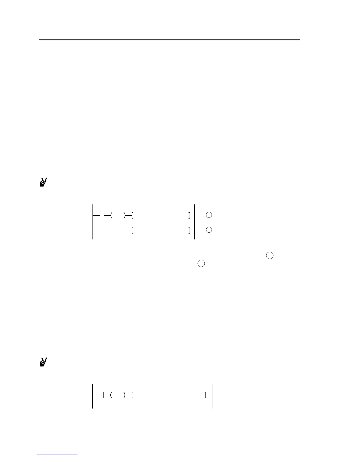
FPΣ
6.3 High-speed Counter Function
6-13
6.3.5 Instructions Used with High-speed Counter Function
High-speed counter control instruction (F0)
Thisinstructionisusedforcounteroperationssuchassoftwareresetandcountdisable.
Specify this instruction together with the special data register DT90052.
Once this instruction is executed, the settings will remain until this instruction is
executed again.
Operations that can be performed with this instruction
- Counter software reset
- Counting operation enable/disable
- Hardware reset enable/disable
- Clear controls from high-speed counter instructions
F166
to
F176
- Clear target value match interrupt
Example:
Performing a software reset
X7
F0 MV, H 1 , DT90052
⋅⋅⋅⋅⋅⋅⋅
1
⋅⋅⋅⋅⋅⋅⋅
2
F0 MV, H 0 , DT90052
DF
Figure 71: FPΣ Program of high-speed counter control instruction “F0”
In the above program, the reset is performed in step1and 0
is entered just after that in step
2
. The count is now ready for
operation. If it is only reset, counting will not be performed.
Elapsed value change and read instruction (F1)
This instruction changes or reads the elapsed value of the high-speed counter.
Specify this instruction together with the special data register DT90044.
The elapsed value is stored as 32-bit data in the combined area of special data
registers DT90044 and DT90045.
Use this
F1 (DMV)
instruction to set the elapsed value.
Example 1:
Changing the elapsed value.
X7
DF F1 DMV, K3000, DT90044
Set the initial value of K3000
in the high-speed counter
Figure 72: FPΣ Program (1) of elapsed value change and read instruction “F1”
Page 89
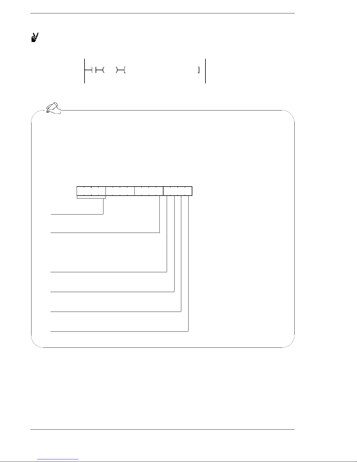
FPΣ
High-speed Counter and Pulse Output Functions
6-14
Example 2:
Reading the elapsed value
X7
DF F1 DMV, DT90044, DT100
Readtheelapsed valueof the
high-speed counter and copies it to DT100 and DT101
Figure 73: FPΣ Program (2) of elapsed value change and read instruction “F1”
The area DT90052 for writing channels and control codes is allocated as shown
below.
Control codes written with an F0(MV) instruction are stored by channel in special
data registers DT90190 to DT90193.
High-speed counter control flag area of FPΣ
Tip
15 12 11 8
Near home input
0: off
1: on
Clear high-speed counter instruction
0: Continue
1: Clear
Pulse output
0: Continue
1: Stop
Hardware reset
0: Permit
1: Prohibit
Count
0: Permit
1: Prohibit
Software reset
0: No
1: Yes
DT90052:
Channel specification
H0 to H3: CH0 to CH3
7430
Page 90
FPΣ
6.3 High-speed Counter Function
6-15
Target value match on instruction (F166)
Example 1:
XA
DF F166 HC1S, K0, K10000, Y7
If the elapsed value
(DT90044 and DT90045) for
channel 0 matches K10000,
output Y7 turns on.
Figure 74: FPΣ Program (1) of target value match on instruction “F166”
Example 2:
XB
DF F166 HC1S, K2, K20000, Y6
If the elapsed value
(DT90200 and DT90201) for
channel 2 matches K20000,
output Y6 turns on.
Figure 75: FPΣ Program (2) of target value match on instruction “F166”
Target value match off instruction (F167)
Example 1:
XC
DF F167 HC1R, K1, K30000, Y4
If the elapsed value
(DT90048 and DT90049) for
channel 1 matches K30000,
output Y4 turns off.
Figure 76: FPΣ Program (1) of target value match off instruction “F167”
Example 2:
XD
DF F167 HC1R, K3, K40000, Y5
If the elapsed value
(DT90204 and DT90205) for
channel 3 matches K40000,
output Y5 turns off.
Figure 77: FPΣ Program (2) of target value match off instruction “F167”
Page 91
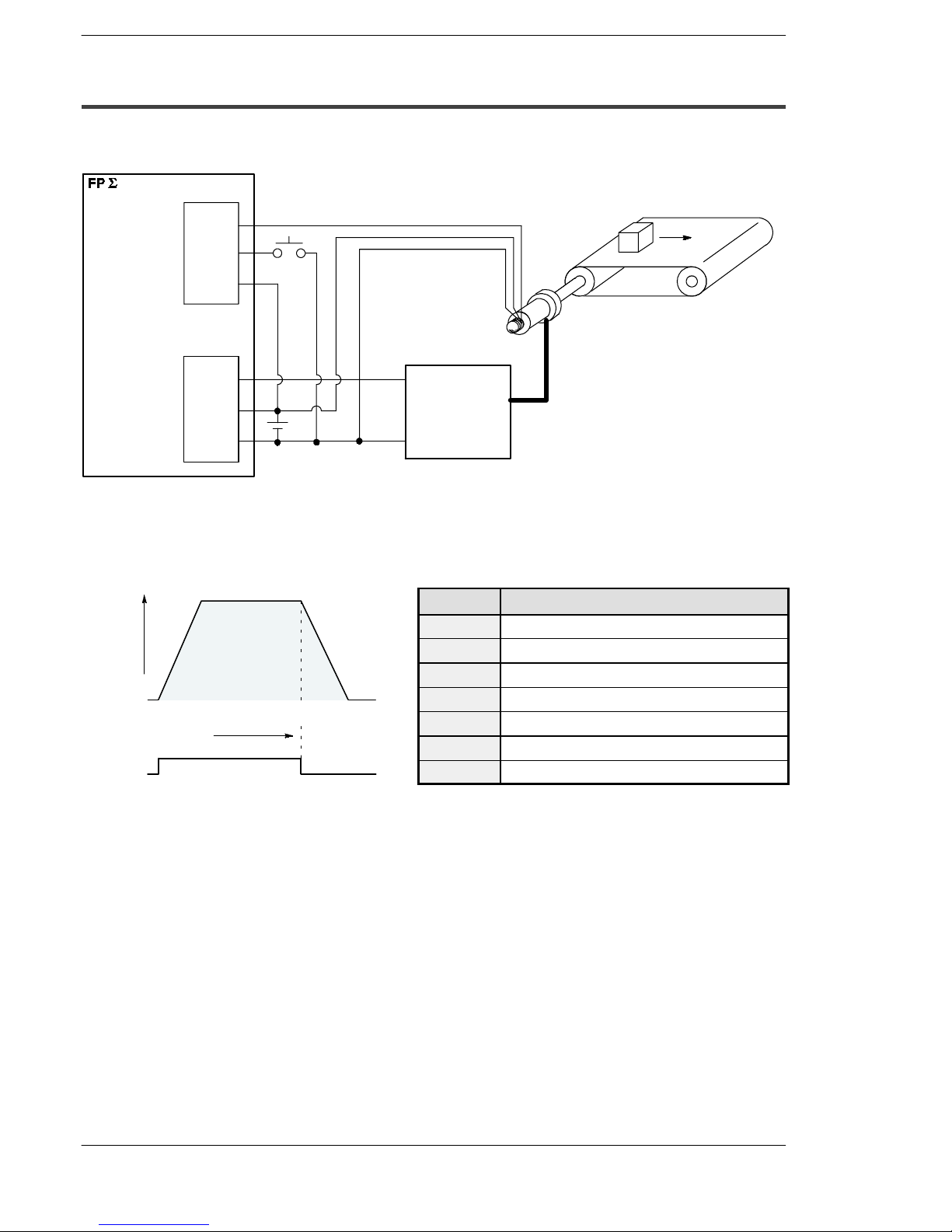
FPΣ
High-speed Counter and Pulse Output Functions
6-16
6.3.6 Sample Program
Positioning operations with a single speed inverter
Y0
+
–
X0
X5
COM
Encoder input
Operation start
Input terminal
Output terminal
Inverter operation
Encoder
Motor
Operation/Stop
Inverter
COM
Conveyor
Wiring example
Figure 78: FPΣ High-speed counter function - sample program 1 (wiring)
I/O No. Description
X0
Encoder input
X5
Operation start signal
Y0
Inverter operation signal
R100
Positioning operation running
R101
Positioning operation start
R102
Positioning done pulse
R903A
High-speed counter CH0 control flag
Figure 79: FPΣ High-speed counter function - sample program 1 (operation chart)
Y0
Speed
Number of pulse
50000
Operation chart I/O allocation
Page 92
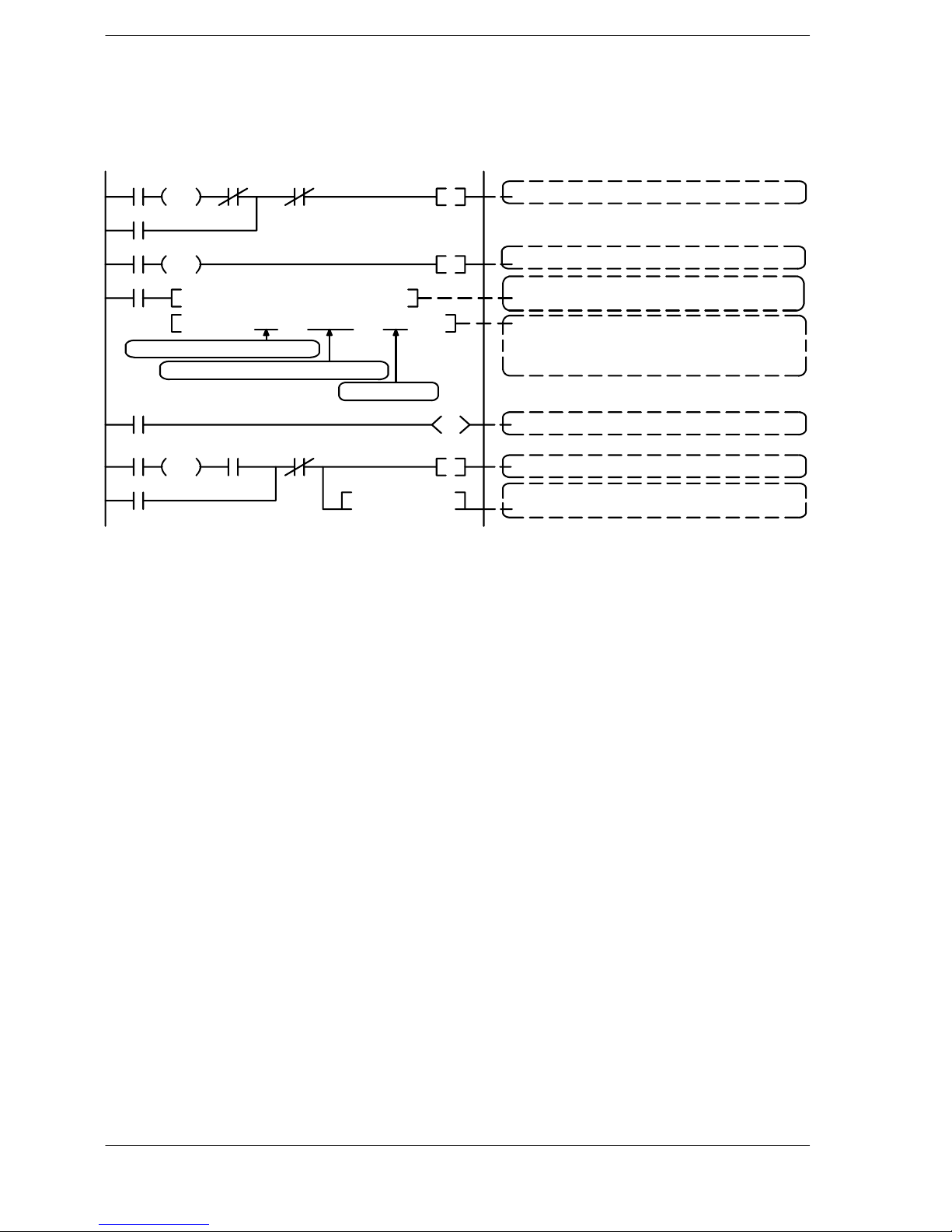
FPΣ
6.3 High-speed Counter Function
6-17
DF
X5 R100R903A R102
Positioning operations running
R100
DF
R100
R101
Positioning operations start
R101
F1 DMV K 0 ,DT 90044
F167 HC1R K 0 ,K 5000 ,Y 0
Sets high-speed counter CH0
DF/
R903A R102
R102
R100 T0
TMX 0, K 5
R101
Y0
S
Resets elapsed value of high-speed counter
CH0
Target value match off instruction
Y0 goes off when elapsed value of high-speed
counter CH0 reaches 5,000 pulses
Set the inverter operation signal “Y0”
Posotioning done pulse (0.5 s)
0.1 s type timer
Setting K5 and using it as a 0.5 s timer
Program
When X5 is turned on, Y0 turns on and the conveyor begins moving. When the elapsed
value (DT90044 and DT90045) reaches K5000, Y0 turns off and the conveyor stops.
Y0 goes off
When elapsed value reaches 5,000
Figure 80: FPΣ High-speed counter function - sample program 1 (program)
Page 93
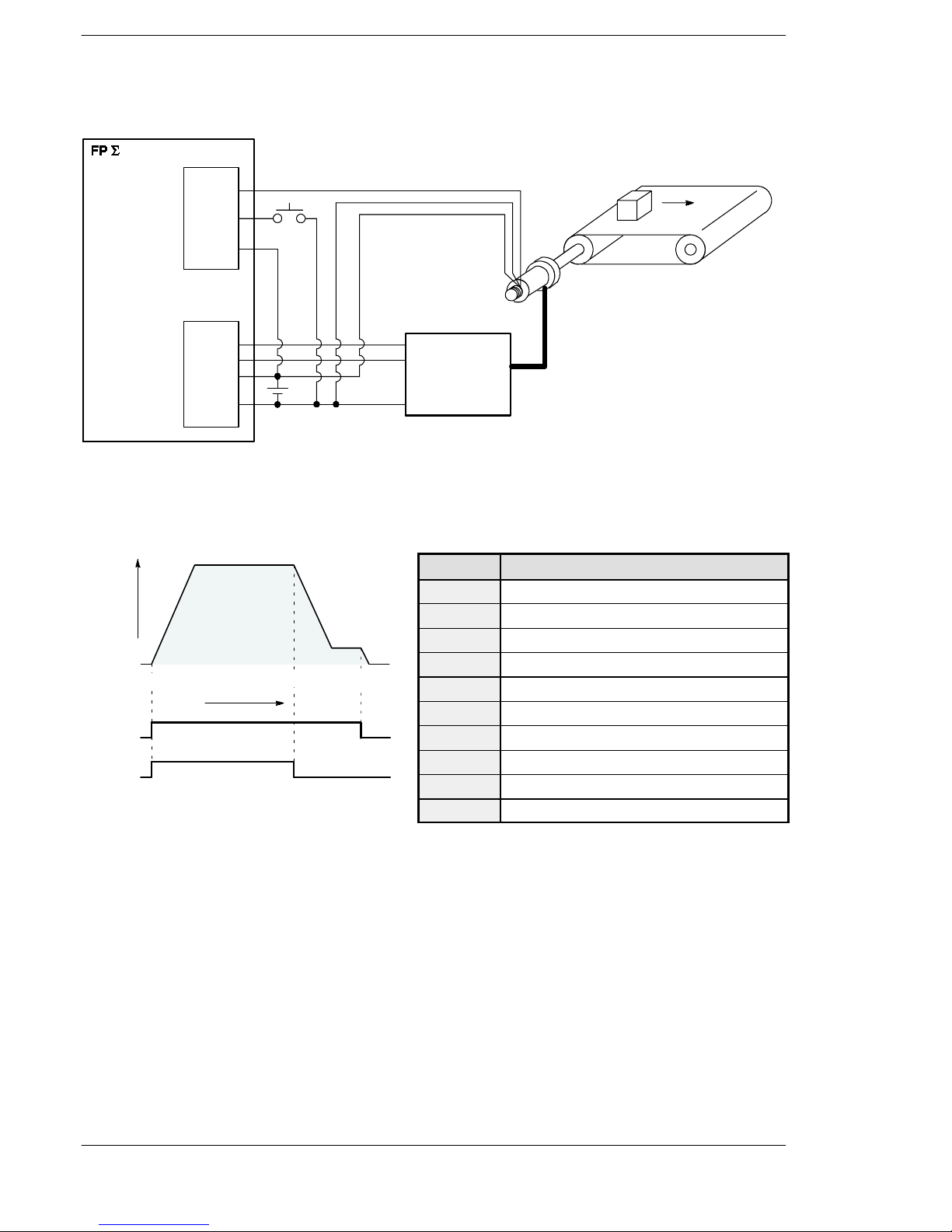
FPΣ
High-speed Counter and Pulse Output Functions
6-18
Positioning operations with a double speed inverter
Y0
Y1
+
-
X0
X5
COM
COM
Input terminal
Output terminal
Encoder
Motor
Operation/Stop
Inverter
Conveyor
Wiring example
Fast/Slow
Encoder input
Operation start
Inverter operation
Inverter
high-speed
Figure 81: FPΣ High-speed counter function - sample program 2 (wiring)
I/O No. Description
X0
Encoder input
X5
Operation start signal
Y0
Inverter operation signal
Y1
Inverter high-speed signal
R100
Positioning operation running
R101
Positioning operation start
R102
Arrival at deceleration point
R103
Positioning done pulse
R900C
Comparison instruction “<” flag
R903A
High-speed counter CH0 control flag
Figure 82: FPΣ High-speed counter function - sample program 2 (operation chart)
Y0
50004500
Y1
0
Speed
Number of pulse
Operation chart I/O allocation
Page 94
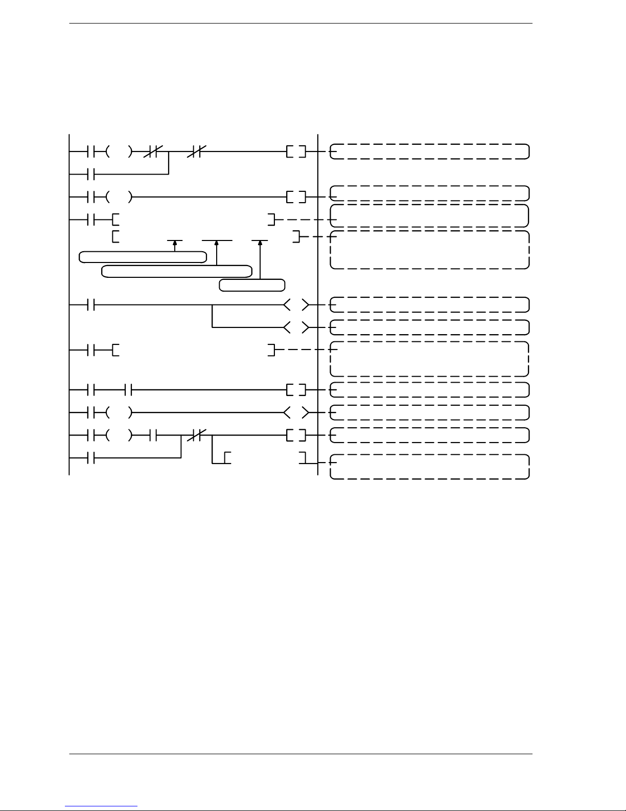
FPΣ
6.3 High-speed Counter Function
6-19
Program
When X5 is turned on, Y0 and Y1 turn on and the conveyor begins moving. When the
elapsed value (DT90044 and DT90045) reaches K4500, Y1 turns off and the conveyor begins decelerating. When the elapsed value reaches K5000, Y0 turns off and the conveyor
stops.
R101
DF
X5
R100
R100
R903A R103
DF
R100
R101
DF/
R903A R103
R103
R100 T0
TMX 0, K 5
R101 Y0
S
Y1
S
R100
DF
R102
Y1
R
R100 R102R900C
F1 DMV K 0 ,DT 90044
F167 HC1R K 0 ,K 5000 ,Y 0
F61 DCMP K 4500 DT 90044
Positioning operations running
Positioning operations start
Resets elapsed value of high-speed counter
CH0
Target value match off instruction
Y0 goes off when elapsed value of high-speed
counter CH0 reaches 5,000 pulses
Set the inverter operation signal “Y0”.
Set theinverter high-speed signal“Y1”.
32-bit data comparison instruction
R900C turns on when the CH0 high-speed counter
elapsed value becomes greater than 4500 pulses.
Speed reduction point reached
Reset the inverter high-speed signal “Y1”.
Positioning done pulse (0.5 s)
Sets high-speed counter CH0
Y0 goes off
When elapsed value reaches 5,000
0.1 s type timer
Setting K5 and using it as a 0.5 s timer
Figure 83: FPΣ High-speed counter function - sample program 2 (program)
Page 95

FPΣ
High-speed Counter and Pulse Output Functions
6-20
6.4 Pulse Output Function
This section explains about the pulse output function of FPΣ.
6.4.1 Overview of Pulse Output Function
Instructions used and controls
The pulse output function enables positioning control by use in combination with a
commercially available pulse-string input type motor driver.
Providestrapezoidal(table-shaped) control with the exclusiveinstructionF171 (SPDH)
for automatically obtaining pulse outputs by specifying the initial speed, maximum
speed, acceleration/deceleration time, and target value.
The exclusive instruction F171 (SPDH) also enables automatic home return operation.
A dedicated instruction, F172 (PLSH), is available for jogging operation, which causes
pulses to be output as long as the execution condition is on. A target value can also be
set, so that pulse output stops at the point when the target value is matched.
A dedicated instruction, F174 (PL0H), is available that outputs pulses in conformance
with the data table, so that positioning control can be carried out in accordance with the
data table.
A dedicated instruction, F175 (SPSH), is available for linear interpolation control. This
enables pulses to be output using linear interpolation control, by specifying the
composite speed, the acceleration/deceleration time, and the target value.
A dedicated instruction, F176 (SPCH), is available for circular interpolation control. The
user can select one of two circular forming methods, one by specifying the pass
positions and the other by specifying a center position. Pulses are output using circular
interpolation control, by specifying the various parameters.
Note
The linear interpolation control instruction F175(SPSH) and
circular interpolation control instruction F176(SPCH) can be used
with the C32T2 control unit only.
Setting the system register
When using the pulse output function, set the channels corresponding to system
registers 400 and 401 to “Do not use high-speed counter.”
Page 96
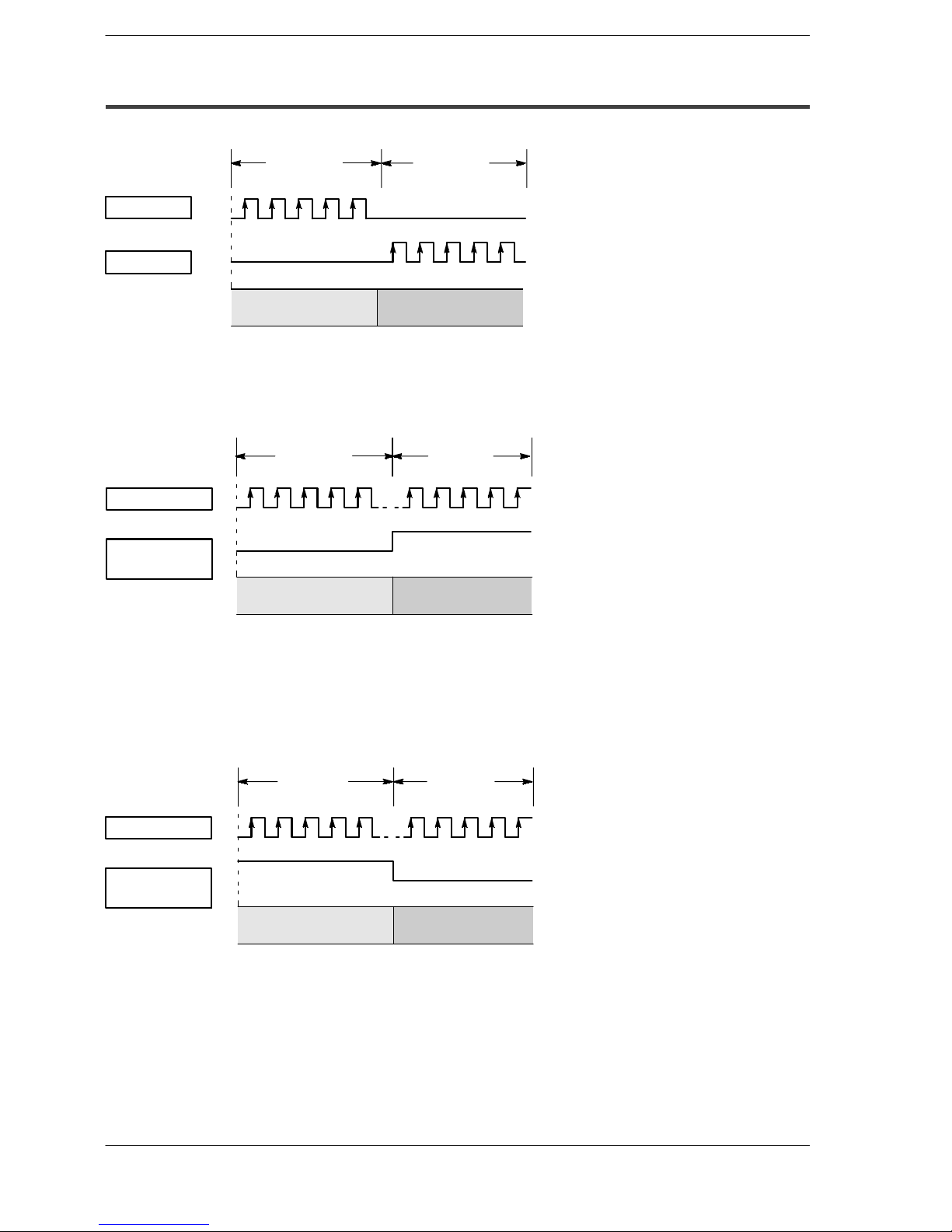
FPΣ
6.4 Pulse Output Function
6-21
6.4.2 Types of Pulse Output Method
Y0
Y1
CCW pulse
CW pulse
Forward Reverse
Direction of increasing elapsed value
Direction of decreasing elapsed value
CW/CCW output method
This is a method in which control is carried out using two pulses,
a forward rotation pulse and a reverse rotation pulse.
Figure 84: FPΣ Pulse output function - CW/CCW output method
Y0
Y1
ONOFF
Rotation
direction [Sign]
Pulse [Pulse]
Forward Reverse
Direction of increasing elapsed value
Direction of decreasing elapsed value
This is a method in which control is carried out using one pulse output to
specify the speed, and on/off signals to specify the direction of rotatin.
In this mode, forward rotation is carried out when the rotation direction
(Sign) signal is off.
Pulse/Sign output method (Forward: off/Reverse: on)
Figure 85: FPΣ Pulse output function - Pulse/sign output method 1
Y0
Y1
OFFON
Forward Reverse
Rotation
direction [Sign]
Pulse [Pulse]
Direction of increasing elapsed value
Direction of decreasing elapsed value
This is a method in which control is carried out using one pulse output to
specify the speed, and on/off signals to specify the direction of rotatin.
In this mode, forward rotation is carried out when the rotation direction
(Sign) signal is on.
Pulse/Sign output method (Forward: on/Reverse: off)
Figure 86: FPΣ Pulse output function - Pulse/sign output method 2
Page 97
FPΣ
High-speed Counter and Pulse Output Functions
6-22
6.4.3 I/O Allocation
Double pulse input driver (CW pulse input and CCW pulse input method)
Two output contact are used as a pulse output for “CW, CCW”.
TheI/O allocation of pulseoutput terminal and homeinput is determined bythe channel
used. (See the table of specifications on page 6 - 6.)
Set the control code for F171 (SPDH) instruction to “CW/CCW”.
X2
X3
Y0
Home input
Near home
input
CW output
*
Y1
CCW output
Driver
When using CH0
* X3 or other desired input can
be specified for the near home input.
Figure 87: FPΣ Pulse output function -
I/O allocation when using CH0
(double pulse input)
X5
X6
Y3
Home input
Near home
input
CW output
*
Y4
CCW output
Driver
When using CH2
* X6 or other desired input can
be specified for the near home input.
Figure 88: FPΣ Pulse output function - I/O allocation
when using CH2 (double pulse input)
Single pulse input driver (pulse input and directional switching input method)
One output point is used as a pulse output and the other output is used as a direction
output.
The I/O allocation of pulse output terminal, direction output terminal, and home input
is determined by the channel used. (See the table of specifications on page 6 - 6.)
Near home input is substituted by allocating the desired contact and turning on and off
the specified bit of special data register DT90052.
Up to two driver systems can be connected.
X2
X3
Y0
Home input
Near home
input
Pulse output
*
Y1
Directional
switching
output
Driver
When using CH0
* X3 or other desired input can
be specified for the near home input.
Figure 89: FPΣ Pulse output function -
I/O allocation when using CH0
(single pulse input)
X5
X6
Y3
Home input
Near home
input
Pulse output
*
Y4
Directional
switching
output
Driver
When using CH2
* X6 or other desired input can
be specified for the near home input.
Figure 90: FPΣ Pulse output function -
I/O allocation when using CH2
(single pulse input)
Page 98
FPΣ
6.4 Pulse Output Function
6-23
6.4.4 Control Mode
Incremental <relative value control>
Outputs the pulses set with the target value.
Target
value
Sel
ecte
d
mode
CW/CCW
PLS and SIGN
Forward off/Reverse on
PLS and SIGN
Forward on/Reverse off
Elapsed value
of high-speed
counter
Positive
Pulse output
from CW
Pulse output when direction
output is off
Pulse output when direction
output is on
Addition
Negative
Pulse output
from CCW
Pulse output when direction
output is on
Pulse output when direction
output is off
Subtraction
Absolute <absolute value control>
Outputs a number of pulses equal to the difference between the set target value and
the current value.
Target
value
Selected
mode
CW/CCW
PLS and SIGN
Forward off/Reverse on
PLS and SIGN
Forward on/Reverse off
Elapsed value
of high-speed
counter
Targetvalue
greater than
current value
Pulse output
from CW
Pulse output when direction
output is off
Pulse output when direction
output is on
Addition
Targetvalue
less than
current value
Pulse output
from CCW
Pulse output when direction
output is on
Pulse output when direction
output is off
Subtraction
Home return
Until the home position input (X2 or X5) is entered by executing F171 (SPDH)
instruction, the pulse is continuously output.
To decelerate the movement when near the home, set the bit corresponding to the
special data register DT90052 to off → on → off with the home position proximity input.
Thedifferentialcounter clear output can be output when the return to the home position
has been completed.
JOG operation
Pulses are output from the specified channel while the trigger for F172 (PLSH)
instruction is in the on state. Also, the pulse output can be stopped when the specified
target value is matched.
The direction output and output frequency are specified by F172 (PLSH) instruction.
Page 99
FPΣ
High-speed Counter and Pulse Output Functions
6-24
6.4.5 Instructions Used with Pulse Output Function
Positioning control instruction (F171) (trapezoidal control)
Automatically performs trapezoidal control according to the specified data table.
Generates a pulse from output Y0 at an initial speed of 500Hz, a maximum speed of
5,000Hz, an acceleration/deceleration time of 300ms, and a movement amount of
10,000 pulses.
X8
DF
F1 DMV, H1100, DT100
F1 DMV, K500, DT102
F1 DMV, K5000, DT104
F1 DMV, K300, DT106
F1 DMV, K10000, DT108
F1 DMV, K0, DT110
F171 SPDH, DT100, K0
Figure 91: FPΣ Program of positioning control instruction “F171”
When the program is run, the positioning data table and the pulse output diagram will
be as shown below.
Positioning data table
DT100
DT101
Control code *1 :H 1100
DT102
DT103
Initial speed *2 :500 Hz
DT104
DT105
Maximum speed *2 :5,000 Hz
DT106
DT107
Acceleration/deceleration time *3 :300 ms
DT108
DT109
Target value *4 :10,000pulses
DT110
DT111
Pulse stop :K0
Page 100
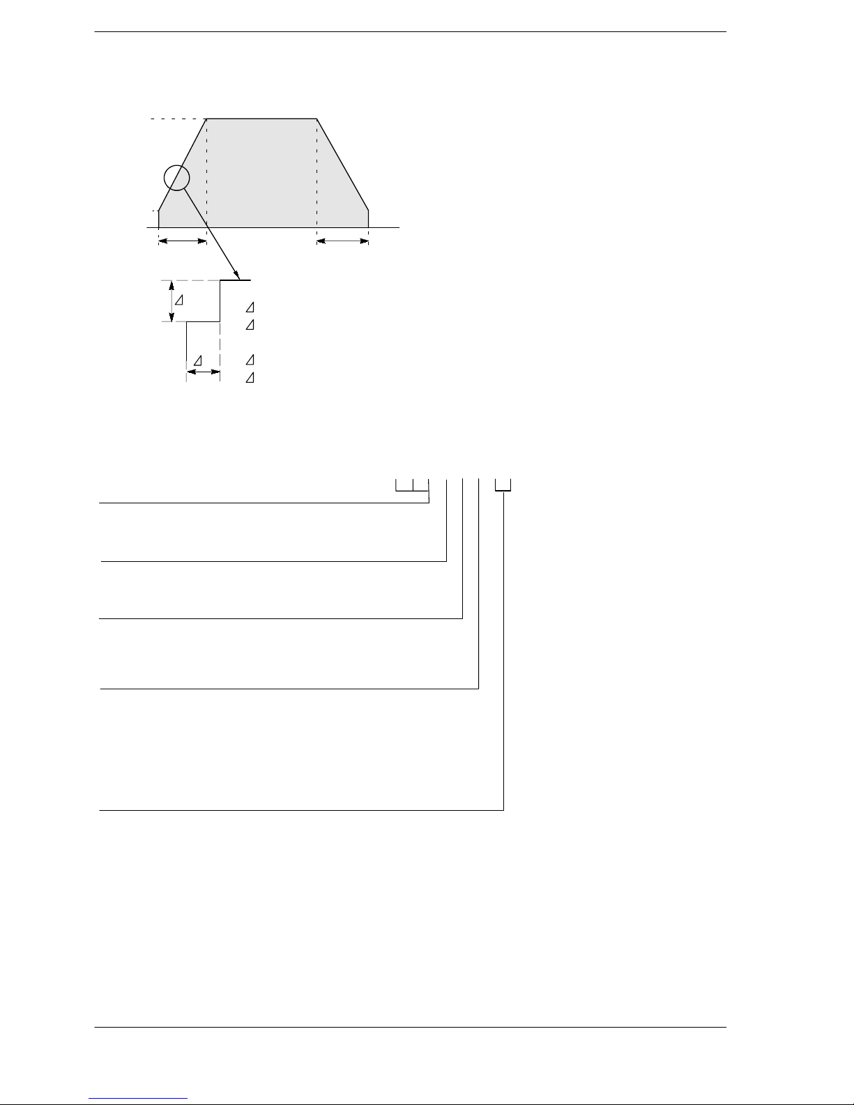
FPΣ
6.4 Pulse Output Function
6-25
Pulse output diagram
300 ms 300 ms
5000 Hz
500 Hz
0Hz
10000 pulses
f
t
f = (5000 - 500) ÷ 30 steps = 150 Hz
With 30 steps:
t = 300 ms ÷ 30 steps = 10 ms
f = (5000 - 500) ÷ 60 steps = 75 Hz
With 60 steps
t = 300 ms ÷ 60 steps = 5 ms
Figure 92: FPΣ Pulse output diagram of “F171” instruction
Operation mode and output method
00: Incremental CW/CCW
02: Incremental PLS and SIGN (forward off / reverse on)
03: Incremental PLS and SIGN (forward on / reverse off)
10: Absolute CW/CCW
12: Absolute PLS and SIGN (forward off / reverse on)
13: Absolute PLS and SIGN (forward on / reverse off)
H jjjjjjjj
0: Fixed
Duty (on width)
0: Duty 1/2 (50%)
1: Duty 1/4 (25%)
Frequency range
0: 1.5 Hz to 9.8 kHz
1: 48 Hz to 100 kHz
2: 191 Hz to 100 kHz
(*1): Control code <H constant>
(*2): Frequency (Hz) “K constant”
1.5 Hz to 9.8 KHz [K1 to K9800 (units: Hz)] (Max. error near 9.8 kHz approximately -0.9 kHz)
* Set “K1” to specify 1.5 Hz.
48 Hz to 100 KHz [K48 to K100000 (units: Hz)] (Max. error near 100 kHz approximately -3 kHz)
191 Hz to 100 KHz [K191 to K100000 (units: Hz)] (Max. error near 100 kHz approximately -0.8 kHz
)
(*3): Acceleration/deceleration time (ms) “K constant”
With 30 steps: K30 to K32767
With 60 steps: K36 to K32767
(*4): Target value “K constant”
K-2147483648 to K2147483647
Number of acceleration/deceleration steps
0: 30 steps
1: 60 steps (Can be specified for only Ver. 2.0 or later.)
Figure 93: FPΣ Control code of “F171” instruction
 Loading...