

NAiS FP, FPS, FPG-C32T, FPG-C32T2, FPG-C24R2 User Manual

PROGRAMMABLE CONTROLLER
User’s Manual
[Applicable PLC]
FPΣControl units
FPG-C32T
•
FPG-C32T2
•
FPG-C24R2
•
FP
Σ
This manual was created using Adobe Acrobat.
Adobe, the Adobe logo, and Acrobat are trademarks
of Adobe Systems Incorporated.
http://www.naisplc.com

Table of Contents
FPΣ
i
Table of Contents
Before You Start viii....................................................
Programming Tool Restrictions xi........................................
Compatibility with the FP0 xii............................................
Chapter 1 Functions and Restrictions of the Unit
1.1 Features and Functions of the Unit 1 - 3...............................
1.2 Unit Types 1 - 6....................................................
1.2.1 FPΣ Control Unit 1 - 6.......................................
1.2.2 FPΣ Expansion Unit 1 - 6.....................................
1.2.3 Units for FP0 and FPΣ 1 - 6..................................
1.2.4 Communication Cassette 1 - 6................................
1.3 Restrictions on Unit Combinations 1 - 7................................
1.3.1 Restrictions on the Number of Expansion Units
(for FP0 expansion unit) 1
-
7.................................
1.3.2 Restrictions on the Number of Units for Expansion
(for FPΣ expansion unit) 1-8.................................
1.4 Programming Tools 1 - 9.............................................
1.4.1 Tools Needed for Programming 1 - 9..........................
1.4.2 Software Environment and Suitable Cable 1 - 9.................
Chapter 2 Specifications and Functions of Control Unit
2.1 Parts and Functions 2 - 3............................................
2.1.1 Parts and Functions 2 - 3....................................
2.1.2 Tool Port Specification 2 - 6..................................
2.1.3 Communication Cassette 2 - 6................................
2.2 Input and Output Specifications 2 - 7..................................
2.2.1 Input Specifications 2 - 7.....................................
2.2.2 Output Specifications 2 - 9...................................
2.3 Terminal Layout Diagram 2 - 12........................................
2.3.1 Control Unit (for C32T and C32T2) 2 - 12.......................
2.3.2 Control Unit (for C24R2) 2 - 12.................................
Chapter 3 Expansion
3.1 Type of Expansion Unit 3 - 3.........................................

Table of Contents FPΣ
ii
3.2 Expansion Method of Units for FP0 and FPΣ 3 - 4.......................
3.3 Expansion Method of FPΣ Expansion Unit 3 - 5.........................
3.4 Specifications of FPΣ Expansion Unit 3 - 6.............................
3.4.1 FPΣ Expansion I/O Unit 3 - 6.................................
Chapter 4 I/O Allocation
4.1 I/O Allocation 4 - 3..................................................
4.1.1 I/O Number of FPΣ Control Unit 4 - 3..........................
4.1.2 I/O Number of FPΣ Expansion Unit (for left side expansion) 4 - 4..
4.1.3 I/O Number of FP0 Expansion Unit (for right side expansion) 4 - 5.
4.1.4 I/O Number of FP0 Analog I/O Unit (for right side expansion) 4 - 5.
4.1.5 I/O Number of FP0 A/D Conversion Unit
(for right side expansion) 4 - 5................................
4.1.6 I/O Number of FP0 I/O Link Unit (for right side expansion) 4 - 6...
Chapter 5 Installation and Wiring
5.1 Installation 5 - 3....................................................
5.1.1 Installation Environment and Space 5 - 3.......................
5.1.2 Installation and Removal 5 - 6................................
5.2 Wiring of Power Supply 5 - 9.........................................
5.2.1 Wiring of Power Supply 5 - 9.................................
5.2.2 Grounding 5 - 11.............................................
5.3 Wiring of Input and Output 5 - 12......................................
5.3.1 Input Wiring 5 - 12...........................................
5.3.2 Output Wiring 5 - 15..........................................
5.3.3 Precautions Regarding Input and Output Wirings 5 - 16...........
5.4 Wiring of MIL Connector Type 5 - 17...................................
5.5 Wiring of Terminal Block Type 5 - 20....................................
5.6 Safety Measures 5 - 22...............................................
5.6.1 Safety Measures 5 - 22.......................................
5.6.2 Momentary Power Failures 5 - 23..............................
5.6.3 Protection of Power Supply and Output Sections 5 - 23...........
5.7 Backup Battery 5 - 24................................................
5.7.1 Installation of Backup Battery 5 - 24............................
5.7.2 System Register Setting 5 - 25.................................
5.7.3 Lifetime of Backup Battery 5 - 26...............................

Table of Contents
FPΣ
iii
Chapter 6 High-speed Counter and Pulse Output Functions
6.1 Overview of Each Functions 6 - 3.....................................
6.1.1 Three Functions that Use Built-in High-speed Counter 6 - 3......
6.1.2 Performance of Built-in High-speed Counter 6 - 4...............
6.2 Function Specifications and Restricted Items 6 - 5......................
6.2.1 Table of Specifications 6 - 5..................................
6.2.2 Function being Used and Restrictions 6 - 7.....................
6.2.3 Booting Time 6 - 9..........................................
6.3 High-speed Counter Function 6 - 10...................................
6.3.1 Overview of High-speed Counter Function 6 - 10.................
6.3.2 Types of Input Modes 6 - 10...................................
6.3.3 Min. Input Pulse Width 6 - 12..................................
6.3.4 I/O Allocation 6 - 12..........................................
6.3.5 Instructions Used with High-speed Counter Function 6 - 13........
6.3.6 Sample Program 6 - 16.......................................
6.4 Pulse Output Function 6 - 20..........................................
6.4.1 Overview of Pulse Output Function 6 - 20.......................
6.4.2 T ypes of Pulse Output Method 6 - 21...........................
6.4.3 I/O Allocation 6 - 22..........................................
6.4.4 Control Mode 6 - 23..........................................
6.4.5 Instructions Used with Pulse Output Function 6 - 24..............
6.4.6 Sample Program for Positioning Control 6 - 43...................
6.5 PWM Output Function 6 - 56..........................................
6.5.1 Overview of PWM Output Function 6 - 56.......................
6.5.2 Instruction Used with PWM Output Function 6 - 56...............
Chapter 7 Communication Cassette
7.1 Communication Functions of FPΣ 7 - 3................................
7.1.1 Functions of Communication Cassette 7 - 3....................
7.2 Communication Cassette 7 - 6........................................
7.2.1 T ype of Communication Cassette 7 - 6.........................
7.2.2 Names and Principle Applications of the Ports 7 - 7..............
7.2.3 Communication Specifications of Communication Cassette 7 - 8..
7.3 Attachment of Communication Cassette 7 - 10...........................
7.3.1 Attachment Procedure 7 - 10..................................

Table of Contents
FPΣ
iv
7.4 Wiring of Communication Cassette 7 - 11...............................
7.4.1 Wiring the Connector with the Communication Cassette 7 - 11.....
7.4.2 Tool for Tightening Communication Connector Terminal Block 7 - 12
7.4.3 Wiring Method 7 - 12.........................................
7.4.4 Cautions Regarding Wiring 7 - 12..............................
Chapter 8 Communication Function 1 Computer Link
8.1 Computer Link 8 - 3.................................................
8.1.1 Overview of Function 8 - 3...................................
8.1.2 Explanation of Operation when Using a Computer Link 8 - 4......
8.1.3 Format of Command and Response 8 - 5......................
8.1.4 Types of Commands that Can Be Used 8 - 8...................
8.1.5 Setting the Communication Parameters when
Using a Computer Link 8 - 10..........................................
8.1.6 Restriction 8 - 10.............................................
8.2 Connection Example with External Device 8 - 11.........................
8.2.1 Connection Example with External Device
(1:1 communication with computer) 8 - 11......................
8.2.2 Connection Example with External Device
(1:1 communication with programmable display “GT10/GT30”) 8 - 14
8.3 Computer Link (1:N communication) 8 - 18..............................
8.3.1 Overview of 1:N Communication 8 - 18.........................
8.3.2 Communication Cassette Used for 1:N Communication 8 - 18......
8.3.3 Settings of System Register and Unit No. 8 - 19..................
8.3.4 Connection with External Device 8 - 22.........................
Chapter 9 Communication Function 2 General-purpose
Serial Communication
9.1 General-purpose Serial Communication 9 - 3..........................
9.1.1 Overview of Function 9 - 3...................................
9.1.2 Program of General-purpose Serial Communication 9 - 5........
9.1.3 Communication Parameter Settings when Using
General-purpose Serial Communications 9
-
6..................
9.2 Overview of Communication with External Devices 9 - 8.................
9.2.1 Data Transmission to External Device 9 - 8.....................
9.2.2 Receiving Data from External Device 9 - 12......................

Table of Contents
FPΣ
v
9.3 Connection Example with External Devices 9 - 16........................
9.3.1 Connection Example with External Device
(1:1 communication with Micro-Imagechecker) 9 - 16.............
9.3.2 Connection Example with External Device
(1:1 communication with FP series PLC) 9 - 22..................
9.4 Data Transmitted and Received with the FPΣ 9 - 29......................
9.5 1:N Communication 9 - 31............................................
9.5.1 Overview of 1:N Communication 9 - 31.........................
9.5.2 Communication Cassette Used with 1 : N Communication 9 - 31...
9.5.3 Setting of System Register 9 - 32..............................
9.6 Flag Operations When Using Serial Communication 9 - 33................
9.6.1 When “STX not exist” is Set for Start Code and “CR” is
Set for End Code 9 - 33.......................................
9.6.2 When “STX” is Set for Start Code and “ETX” is Set for
End Code 9 - 35.............................................
9.7 Changing the Communication Mode of COM. Port 9 - 37..................
Chapter 10 Communication Function 3 PLC Link Function
10.1 PLC Link 10 - 3......................................................
10.1.1 Overview of Function 10 - 3...................................
10.2 Communication Parameter Settings 10 - 5..............................
10.2.1 Setting of Communication Mode 10 - 5..........................
10.2.2 Setting of Unit No. 10 - 6......................................
10.2.3 Allocation of Link Relay and Link Register 10 - 10.................
10.2.4 Setting the Largest Station Number for a PLC Link 10 - 16..........
10.3 Monitoring When a PLC Link is Being Used 10 - 17........................
10.3.1 Monitoring Using Relays 10 - 17.................................
10.4 Connection Example of PLC Link 10 - 18.................................
10.4.1 Using a PLC Link with Three FPΣ Units 10 - 18....................
10.4.2 Sample Programs 10 - 21......................................
10.5 PLC Link Response Time 10 - 22.......................................
10.5.1 PLC Link Response Time 10 - 22................................
10.5.2 Shortening the Transmission Cycle Time When There are
Stations That Have not been Added to the Link 10
-
25.............
10.5.3 Error Detection Time for Transmission Assurance Relays 10 - 26....

Table of Contents
FPΣ
vi
Chapter 11 Other Functions
11.1 Analog Potentiometer 11 - 3...........................................
11.1.1 Overview of Analog Potentiometer 11 - 3........................
11.1.2 Example Showing How the Analog Potentiometers are Used 11 - 3.
11.2 Clock/Calendar Function 11 - 4........................................
11.2.1 Area for Clock/Calendar Function 11 - 4.........................
11.2.2 Setting of Clock/Calendar Function 11 - 4.......................
11.2.3 Precautions Concerning Backup of Clock/Calendar Data 11 - 5....
11.2.4 Example Showing the Clock/Calendar being Used 11 - 6..........
Chapter 12 Self-Diagnostic and Troubleshooting
12.1 Self-Diagnostic Function 12 - 3........................................
12.1.1 LED Display for Status Condition 12 - 3.........................
12.1.2 Operation on Error 12 - 4......................................
12.2 Troubleshooting 12 - 5................................................
12.2.1 If the ERROR/ALARM LED Flashes 12 - 5.......................
12.2.2 If the ERROR/ALARM LED Lights 12 - 7........................
12.2.3 If None of the LEDs Light 12 - 7................................
12.2.4 If Outputting does not Occur as Desired 12 - 8...................
12.2.5 If a Protect Error Message Appears 12 - 10.......................
12.2.6 If the Program Mode does not Change to RUN 12 - 10.............
12.2.7 If a Transmission Error has Occurred 12 - 11.....................
Chapter 13 Specifications
13.1 Table of Specifications 13 - 3..........................................
13.1.1 General Specifications 13 - 3..................................
13.1.2 Performance Specifications 13 - 5..............................
13.2 I/O No. Allocation 13 - 10..............................................
13.3 Relays, Memory Areas and Constants 13 - 12............................
13.4 Table of System Registers 13 - 14.......................................
13.4.1 System Registers 13 - 14......................................
13.4.2 Table of System Registers 13 - 16...............................
13.5 Table of Special Internal Relays 13 - 21..................................
13.6 Table of Special Data Registers 13 - 28..................................

Table of Contents
FPΣ
vii
13.7 Table of Error Cords 13 - 42............................................
13.7.1 Table of Syntax Check Error 13 - 42.............................
13.7.2 Table of Self-Diagnostic Error 13 - 43............................
13.8 Table of Instructions 13 - 44............................................
13.9 MEWTOCOL-COM Communication Commands 13 - 66...................
13.10 Hexadecimal/Binary/BCD 13 - 67.......................................
13.11 ASCII Codes 13 - 68..................................................
13.12Dimensions 13 - 69...................................................
13.12.1 Control Unit 13 - 69............................................
13.12.2 Expansion Unit 13 - 70.........................................
Index
I-1..............................................................
Record of changes
R-1..............................................

Before You Start FPΣ
viii
Before You Start
Installation environment
Do not use the FPΣ unit where it will be exposed to the following:
Direct sunlight and ambient temperatures outside the
range of 0_Cto55_C/32_F to 131_F.
Ambient humidity outside the range of 30% to 85% RH
and sudden temperature changes causing condensation.
Inflammable or corresive gas.
Excessive vibration or shock.
Excessive airborne dust, metal particles or salts.
Water or oil in any from including spray or mist.
Benzine, paint thinner, alcohol or other organic solvents
or strong alkaline solutions such as ammonia or caustic
soda.
Influence from power transmission lines, high voltage
equipment, power cables, power equipment, radio
transmitters, or any other equipment that would generate
high switching surges.
Static electricity
Before touching the unit, always touch a grounded piece
of metal in order to discharge static electricity.
In dry locations, excessive static electricity can cause
problems.
Cleaning
Do not use thinner based cleaners because they deform
the unit case and fade the colors.
Power supplies
An insulated power supply with an internal protective
circuit should be used. The power supply for the control
unit operation is a non-insulated circuit, so if an
incorrect voltage is directly applied, the internal circuit
may be damaged or destroyed.
If using a power supply without a protective circuit,
power should be supplied through a protective element
such as a fuse.

Before You Start
FPΣ
ix
Power supply sequence
Have the power supply sequence such that the power
supply of the control unit turns off before the power
supply for input and output.
If the power supply for input and output is turned off
before the power supply of the control unit, the control
unit will detect the input fluctuations and may begin an
unscheduled operation.
Before turning on the power
Whenturningonthepowerfor the first time, be sure to taketheprecautionsgivenbelow.
When performing installation, check to make sure that
there are no scraps of wiring, particularly conductive
fragments, adhering to the unit.
Verify that the power supply wiring, I/O wiring, and power
supply voltage are all correct.
Sufficiently tighten the installation screws and terminal
screws.
Set the mode selector to PROG. mode.
Before entering a program
Be sure to perform a program clear operation before entering a program.
Operation procedure when using FPWIN GR Ver.2
Procedure:
1. Select “On
line Edit Mode” on the FPWIN GR
“On l
ine” menu.
2. Select “Cl
ear Program” on the “Edit” menu.
3. When the confirmation dialog box is displayed, click
on “Y
es” to clear the program.

Before You Start
FPΣ
x
Request concerning program storage
To prevent the accidental loss of programs, the user should consider the following
measures.
Drafting of documents
To avoid accidentally losing programs, destroying files, or
overwriting the contents of a file, documents should be
printed out and then saved.
Specifying the password carefully
The password setting is designed to avoid programs being
accidentally overwritten. If the password is forgotten,
however, it will be impossible to overwrite the program even if
you want to. Also, if a password is forcibly bypassed, the
program is deleted. When specifying the password, note it in
the specifications manual or in another safe location in case
it is forgotten at some point.
Programming Tool Restrictions
FPΣ
xi
Programming Tool Restrictions
Type of programming tool Instruction used/function restrictions
Windows software
Conforms to IEC61131-3
FPWIN Pro Ver.4
All instructions and functions can be used.
FPWIN GR Ver.2
All instructions and functions can be used.
W
ind
ows software
FPWIN GR Ver.1
Not used
NPST-GR Ver.4
MS-DOSsof
tware
NPST-GR Ver.3
N
ot use
d
AFP1114V2
Handy programming unit
AFP1114
y
pg g
(FP programmer)
AFP1112A
AFP1112
Not
used
Notes
Precautions concerning programming tools
Programming tools used with the FPΣ require FPWIN Pro Ver. 4 or
later or Ver . 2 or a subsequent version of the FPWIN GR. Please be
aware that other tools cannot be used.
Either “FPWIN Pro Ver.4.1 or later” or “FPWIN GR Ver. 2.1 or later”
are necessary for use the C32T2 and C24R2 types control unit.

Compatibility with the FP0
FPΣ
xii
Compatibility with the FP0
Program compatibility
The following points require attention if using FP0 programs on the FPΣ.
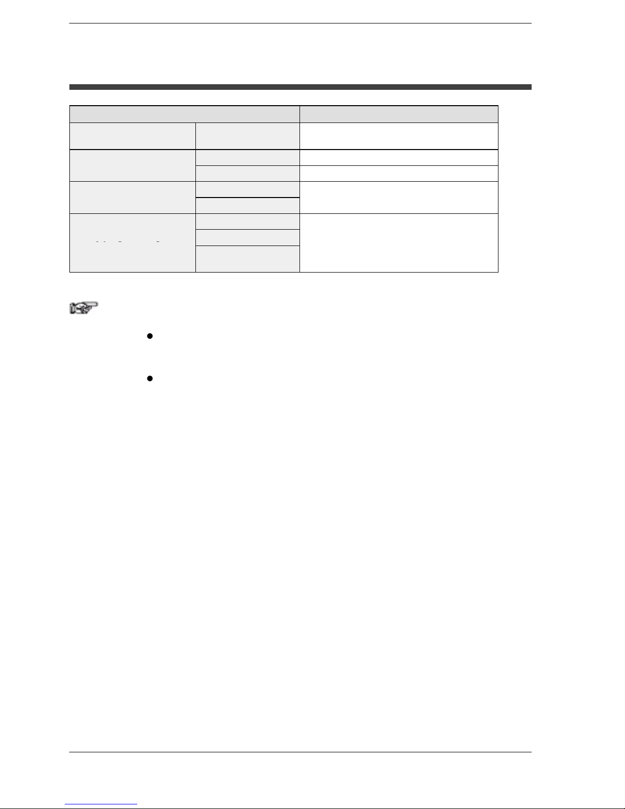
Pulse output function
With the FPΣ, please be aware that the following changes
have been made to instructions concerning pulse output.
Instruction For the FP0 For the FPΣ
Trapezoidal control
F168 (SPD1) F171 (SPDH)
Jog feed
F169 (PLS) F172 (PLSH)
Data table control
None F174 (SP0H)
Linear interpolation control
None F175 (SPSH)
Circular interpolation control
None F176 (SPCH)
PWM output
F170 (PWM) F173 (PWMH)
* Linear and circular interpolation control can be used only with the
FPΣ Control Unit C32T2.
Serial data communication function
With the FPΣ, please be aware that the following changes
have been made to instructions concerning serial data
communication.
Instruction For the FP0 For the FPΣ
Serial data communication
F144 (TRNS) F159 (MTRN)
* The F159 (MTRN) instruction is used only with an FPΣ in which
the conventional F144 (TRNS) instruction has been set up to
correspond to multiple communication ports. Please be aware
that the conventional F144 (TRNS) instruction cannot be used
with the FPΣ.

Chapter 1
Functions and Restrictions of the Unit
1.1 Features and Functions of the Unit 1 - 3................
1.2 Unit Types 1 - 6......................................
1.3 Restrictions on Unit Combinations 1 - 7.................
1.4 Programming Tools 1 - 9..............................

FPΣFunctions and Restrictions of the Unit
1-2
FPΣ 1.1 Features and Functions of the Unit
1-3
1.1 Features and Functions of the Unit
Powerful control capabilities
All of the functions of a mid-scale PLC are packed into the compact body size of the
32-point type FP0. A program capacity of 12 k steps is provided as a standard feature,
so you never have to worry about how much memory is left as you’re programming. In
addition, 32 k words are reserved for data registers, so large volumes of data can be
compiled and multiple operations can be processed without running out of memory.
A full range of communication functions
Using the Tool port (RS232C) provided as a standard feature on the main unit,
communication can be carried out with a display panel or computer. Additionally,
communication cassettes with RS232C and RS485 interfaces are available as an
option. Installing a 2-channel RS232C type communication cassette in the FPΣ makes
it possible to connect two devices with RS232C port. A full lineup of communication
functions means you can also work with 1:N communication and PLC link function (up
to 16 units).
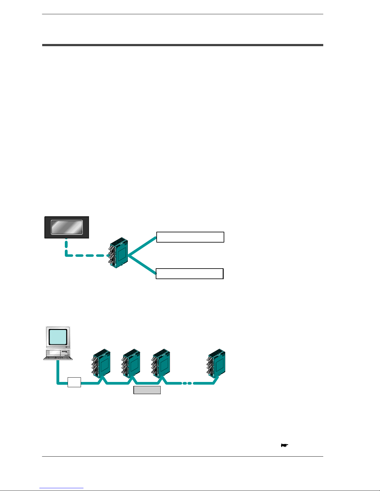
Controlling two devices with RS232C port with one FP
Σ
Display panel
The Toolport can beused
toconnecta displaypanel
or other device.
Device with RS232C port
When using the 2-channel RS232C type communication cassette
Two devices with RS232C port can be connected.
Device with RS232C port
FPΣ
Figure 1: Features-communication (RS232C)
1:N communication possible with up to 99 stations (units)
Communication is possible with up to 99 units.
Commercial adapter
Computer
When using the 1-channel RS485 type communication cassette
FPΣ
No.1
FPΣ
No.2
FPΣ
No.3
FPΣ
No.99
RS485
Figure 2: Features-communication (C-NET)
next page
FPΣ
Functions and Restrictions of the Unit
1-4
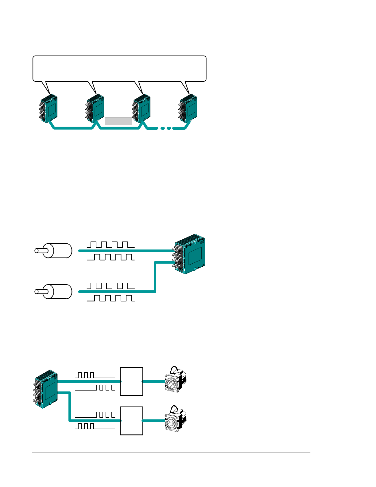
Data can be shared among up to 16 FPΣ units using
the PLC link function.
Data can be shared among the various PLCs using the PLC link function.
When using the 1-channel RS485 type communication cassette
FPΣ
No.1
FPΣ
No.2
FPΣ
No.3
FPΣ
No.16
RS485
Figure 3: Features-communication (PLC link)
Positioning control supported through high-speed counter and pulse output
A high-speed counter and pulse output functions are provided as standard features.
The pulse output function supports frequencies of up to 100 kHz, enabling positioning
control using a stepping motor or servo motor.
Measurement using high-speed counter supported
Encoder
Single phase: Max. 50 kHz, Two-phase: Max. 20 kHz
Encoder
FPΣ
Increment input mode, decrement input mode, 2-phase input mode, individual input mode, and
direction discrimination mode are supported.
Pulse input
Pulse input
Figure 4: Features-High-speed counter
FPΣ
Positioning control based on pulse output supported
Pulse output
1-channel: Max. 100 kHz, 2-channel: Max. 60 kHz
Mortor
driver
CW/CCW and Pulse/sign outputs are supported.
Pulse output
Mortor
driver
Mortor
Mortor
Figure 5: Features-Pulse output

FPΣ
1.1 Features and Functions of the Unit
1-5
Analog control supported
An analog potentiometer (volume dial) is provided as a standard feature. This can be
used in applications such as analog timers, without using the programming tools. An
analog unit is also available as the intelligent unit.

FPΣ
Functions and Restrictions of the Unit
1-6
1.2 Unit Types
This section explains the type of unit used with the FPΣ and about the optional
communication cassette.
1.2.1 FPΣ Control Unit
Name Number of I/O points Part No. Product No.
Input: 16 points/Transistor output: 16 points FPG-C32T AFPG2543
FPΣ Control unit
Input: 16 points/Transistor output: 16 points FPG-C32T2 AFPG2643
Input: 16 points/Relay output: 8 points FPG-C24R2 AFPG2423
1.2.2 FPΣ Expansion Unit
Name Number of I/O points Part No. Product No.
FPΣ expansion I/O unit Input: 32 points/Transistor output: 32 points FPG-XY64D2T AFPG3467
* The FPΣ expansion I/O unit can be used for “FPG-C32T2 and FPG-C24R2” FPΣ
control units.
1.2.3 Units for FP0 and FPΣ
The FPΣ can be used the FP0 series expansion I/O unit, power supply unit, and
intelligent unit.
1.2.4 Communication Cassette
A detachable communication cassette (optional) should be used when using the
various functions such as the computer link, serial data communication, and PLC link
functions.
Name Description Part No. Product No.
FPΣ Communication
cassette 1-channel
RS232C type
This communication cassette is a 1-channel unit with
a five-wire RS232C port. It supports 1 : 1 computer
links and general-purpose serial communication. RS/
CS control is possible.
FPG-COM1 AFPG801
FPΣ Communication
cassette 2-channel
RS232C type
This communication cassette is a 2-channel unit with
a three-wire RS232C port. It supports 1 : 1 computer
links and general-purpose serial communication.
Communication with two external devices is possible.
FPG-COM2 AFPG802
FPΣ Communication
cassette 1-channel
RS485 type
This communication cassette is a 1-channel unit with
a two-wire RS485 port. It supports 1 : N computer
links(C-NET),general-purposeserialcommunication,
and a PLC link.
FPG-COM3 AFPG803
FPΣ
1.3 Restrictions on Unit Combinations
1-7
1.3 Restrictions on Unit Combinations
This section contains restrictions on unit combinations.
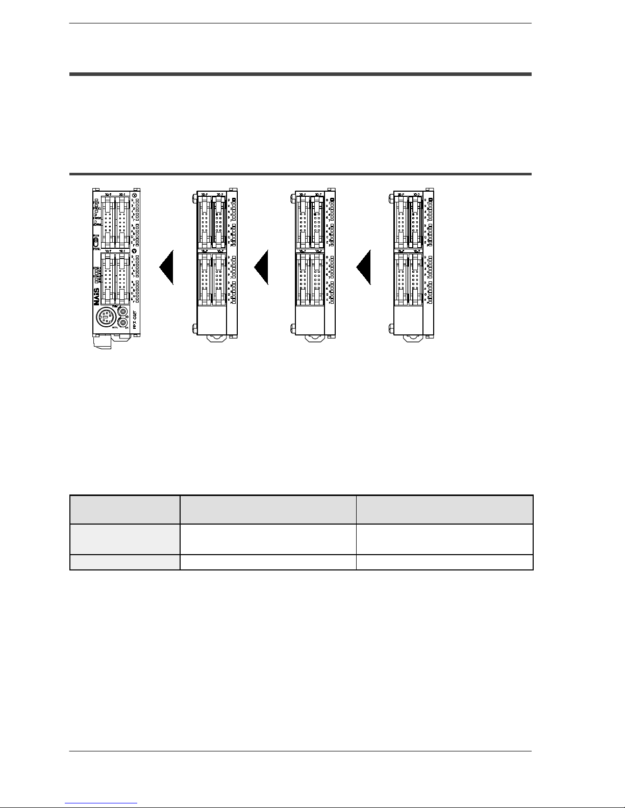
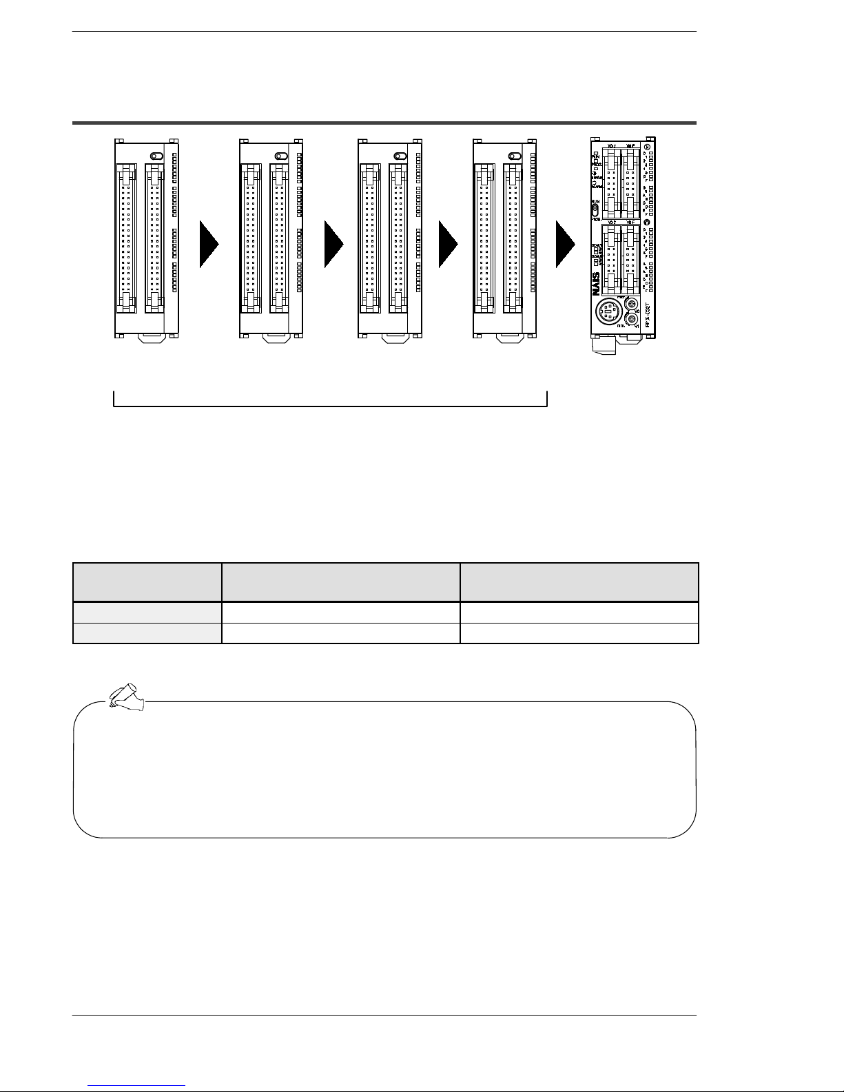
1.3.1 Restrictions on the Number of Expansion Units
(for FP0 expansion unit)
Control unit Unit 1 for expansion
(Maximum possible
expansion is with a
total of three units)
Unit 2 for expansion Unit 3 for expansion
Figure 6: Restriction on unit combinations
Up to three expansion units can be added at the right of the FPΣ, these expansion units being
either expansion units or intelligent units from the earlier FP0 series, or a combination of the
two.
There are no restrictions on the type and the order in which expansion units are installed.
A combination of relay output types and transistor output types is also possible.
Controllable I/O Points
Type of control unit
Number of I/O points when using
control unit
Number of I/O points when using
FP0 expansion unit
FPG-C32T
FPG-C32T2
32 points Max. 128 points
FPG-C24R2 24 points Max. 120 points
FPΣ
Functions and Restrictions of the Unit
1-8
1.3.2 Restrictions on the Number of Units for Expansion (for FPΣ
expansion unit)
Control unitExpansion unit 1Expansion unit 2Expansion unit 3Expansion unit 4
Max. possible expansion is with a total of four units.
Up to four dedicated FPΣ expansion units can be added at the left of the FPΣ.
The 64 points type expansion unit consist of 32 input points and 32 transistor output
points.
Controllable I/O Points
Type of control unit
Number of I/O points when using
control unit
Number of I/O points when using
FPΣ expansion unit
FPG-C32T2 32 points Max. 288 points
FPG-C24R2 24 points Max. 280 points
The FPΣ expansion unit cannot be used for FPG-C32T.
Tip
If using FP0 expansion units and FPΣ expansion units in combination, the number
of input and output points can be expanded to a maximum of 384 points for the
FPG-C32T2 and 376 points for the FPG-C24R2.
FPΣ
1.4 Programming Tools
1-9
1.4 Programming Tools
This section explains about the programming tools for FPΣ.
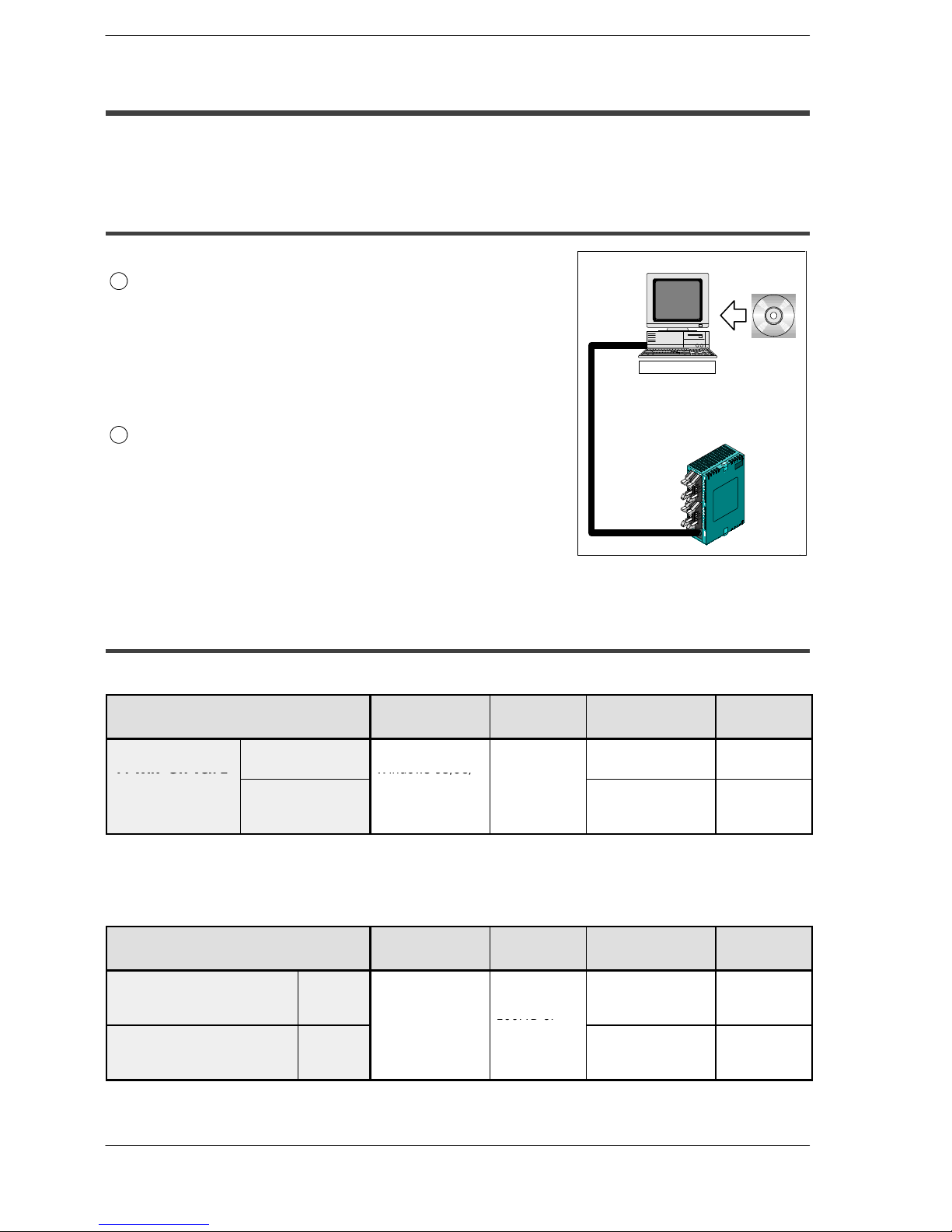
1.4.1 Tools Needed for Programming
FPΣ
Computer
PC connection cable
1
Programming tool software
The tool software can also be used with the FP series.
The “FPWIN Pro Ver. 4” or “FPWIN GR Ver. 2” Windows
software is used with the FPΣ.
The earlier FPWIN GR Ver. 1x, NPST-GR, and FP Programmer cannot be used.
2
PC connection cable
This cable needed for connection between the FPΣ and
the computer.
Programming
tool software
FPΣ
Figure 7: Programming tools
1.4.2 Software Environment and Suitable Cable
Standard ladder diagram tool software “FPWIN-GR Ver.2”
Type of software
OS (Operating
system)
Hard disk
capacity
Part No.
Product
No.
FPWIN-GR Ver. 2
English-language
software
Windows 95/98/
FPWINGRF-EN2 AFPS10520
FPWIN
GRVer.2
English-language
menu
Upgrade (to
upgrade from
Ver.1.1)
Windows
95/98/
Me/2000/NT
(Ver. 4.0 or later)
30MB or more
FPWINGRR-EN2 AFPS10520R
Conforms to IEC61131-3 programming tool software “FPWIN-Pro Ver.4”
Type of software
OS (Operating
system)
Hard disk
capacity
Part No.
Product
No.
FPWIN Pro Ver. 4 Full type
(for all type FP series PLC)
Englishlanguage
menu
Windows 95/98/
100MB or
FPWINPROF-EN4 AFPS50540
FPWIN Pro Ver. 4 Small type
(for FP0, FPΣ, FP1, and
FP-M)
Englishlanguage
menu
Me/
2000
/NT
(Ver. 4.0 or later)
100MB
or
more
FPWINPROS-EN4 AFPS51540

FPΣ
Functions and Restrictions of the Unit
1-10
Type of computer and suitable cable
Type of computer Cable Cable specification
IBM PC/AT or
Part No.: AFC8503 D-Sub 9-pin female-Mini DIN 5-pin male
IBM
PC/A
T
or
its compatible machine
Part No.: AFC8513 D-Sub 25-pin male-Mini DIN 5-pin male

Chapter 2
Specifications and Functions of Control
Unit
2.1 Parts and Functions 2 - 3.............................
2.2 Input and Output Specifications 2 - 7...................
2.3 Terminal Layout Diagram 2 - 12........................

FPΣSpecifications and Functions of Control Unit
2-2
FPΣ 2.1 Parts and Functions
2-3
2.1 Parts and Functions
This section explains about the parts and functions of FPΣ control unit.
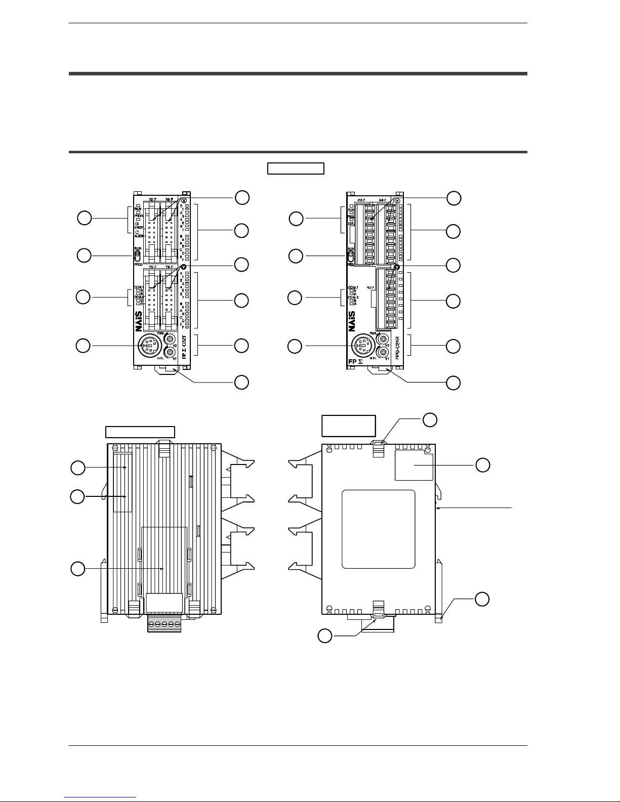
2.1.1 Parts and Functions
EXPANSION
CONNECTOR
FPG-C32T
FPG-C32T2
FPG-C24R2
Front view
Left side view
Right side
view
DIN standard rail
attachment
For all type control unit
1
2
3
4
5
6
7
8
9
10
1
2
3
4
5
6
7
8
9
10
11
13
12
14
14
15
16
Figure 8: FPΣ Parts and Functions
FPΣ
Specifications and Functions of Control Unit
2-4
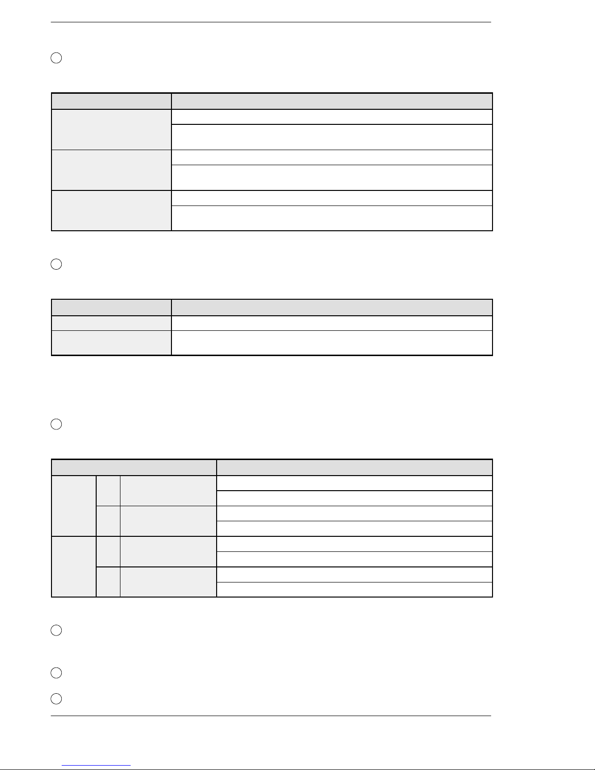
1
Status indicator LEDs
These LEDs display the current mode of operation or the occurrence of an error.
LED LED and operation status
RUN (green) Lights when in the RUN mode and indicates that the program is being executed.
It flashes during forced input/output.
(The RUN and PROG LEDs flash alternately.)
PROG. (green) Lights when in the PROG. mode and indicates that operation has stopped.
It flashes during forced input/output.
(The RUN and PROG LEDs flash alternately.)
ERROR/ALARM (red) Flashes when an error is detected during the self-diagnostic function.
Lights if a hardware error occurs, or if operation slows because of the program, and
the watchdog timer is activated.
2
RUN/PROG. mode switch
This switch is used to change the operation mode of the PLC.
Switch position Operation mode
RUN (upward) This sets the RUN mode. The program is executed and operation begins.
PROG. (downward) This sets the PROG. mode.The operation stops. In this mode, programming canbe
done using tools.
When performing remote switching from the programming tool, the position of the mode
switch and the actual mode of operation may differ. Verify the mode with the status indicator
LED. Otherwise, restart the FPΣ and change the mode of operation with the RUN/PROG.
mode switch.
3
Communication status LEDs
These display the communication status of the COM.1 and COM.2 ports.
LED LED and communication status
COM.1 S Transmitted data
Flashes while data is being transmitted
monitor
Goes out when no data is being transmitted
R Received data
Flashes while data is being received
monitor
Goes out when no data is being received
COM.2 S Transmitted data mo-
Flashes while data is being transmitted
nitor
Goes out when no data is being transmitted
R Received data
Flashes while data is being received
monitor
Goes out when no data is being received
4
Tool port (RS232C)
This port is used to connect a programming tool.
5
Input connector (10 pins × 2)
6
Input indicator LEDs

FPΣ
2.1 Parts and Functions
2-5
7
Output connector (10 pins × 2)
8
Output indicator LEDs
9
Analog potentiometer (analog dial)
Turning this dial changes the values of special data registers DT90040 and DT90041 within
the range of K0 to K1000. It can be used for analog timers and other applications.
10
Power supply connector (24 V DC)
Supply 24 V DC. It is connected using the power supply cable (AFP0581) that comes with the
unit.
11
Left-side connector for FPΣexpansion
This is used to connect dedicated FPΣ expansion units on the left side of the control unit with
the internal circuits.
*The FPG-C32T2 and FPG-C24R2 control units are equipped with this connector, but the
FPG-C32T is not.
12
Unit No. (Station No.) setting switch
This unit No. (station No.) is specified when using the communication functions provided on
the optional communication cassettes.
The unit No. (station No.) setting switch is located under the cover on the back of the
unit. Specify the unit (station) number using the selector switch and the dial.
Figure 9: FPΣ Parts and Functions (Unit No. setting switch)
13
Communication cassette (option)
This is the optional cassette type adapter used when communication is carried out.
Any one of the following the cassette types may be installed.
- 1-channel RS232C type
- 2-channel RS232C type
- 1-channel RS485 type
14
Expansion hook
This hook is used to secure expansion units. The hook is also used for installation on flat type
mounting plate (AFP0804).
15
Right-side connector for FP0 expansion
Connects an expansion unit to the internal circuit of the control unit.
16
DIN rail attachment lever
The FPΣ unit enables attachment at a touch to a DIN rail. The lever is also used for
installation on slim 30 type mounting plate (AFP0811).
FPΣ
Specifications and Functions of Control Unit
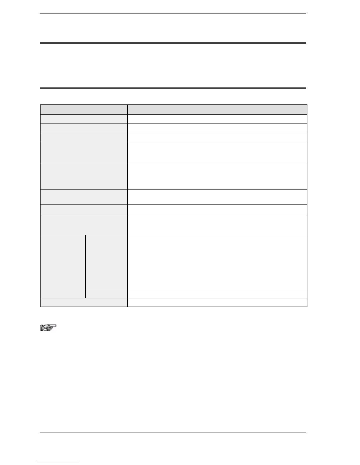
2-6
2.1.2 Tool Port Specification
A commercial mini-DIN 5-pin connector is used for the Tool port on the control unit.
Pin no. Signal name Abbreviation Signal direction
1
Signal Ground SG —
2
Transmitted Data SD Unit → External device
3
Received Data RD Unit ← External device
4
(Not used) — —
5
+5V +5V Unit → External device
Figure 10: FPΣ Parts and Functions (Tool port)
The following are the default settings set when the unit is shipped from the factory .The
system registers should be used to change these.
- Baud rate 9600 bps......
- Character bit 8 bit...
- Parity check Odd parity....
- Stop bit length 1 bit..
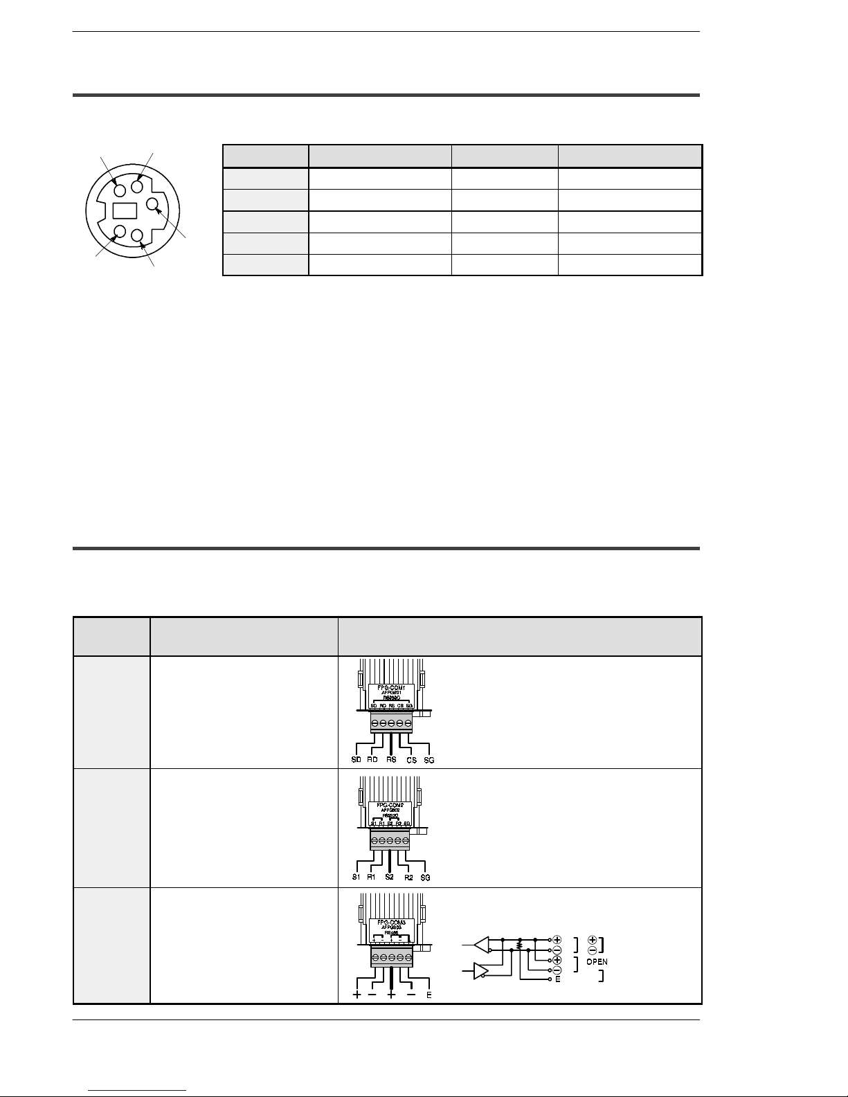
2.1.3 Communication Cassette
The detachable communication cassette (optional) can be selected from among the
three types shown below.
Type Applicable communication
function
Terminal layout diagram
1-channel
RS232C
type
Computer link
General-purpose serial
communication
SD: Transmitted Data (Output)
RD: Received Data (Input)
RS: Request to Send (Output)
CS: Clear to Send (Input)
SG: Signal Ground
2-channel
RS232C
type
Computer link
General-purpose serial
communication
S1: Transmitted Data (Output) (COM.1)
R1: Received Data (Input) (COM.1)
S2: Transmitted Data (Output) (COM.2)
R2: Received Data (Input) (COM.2)
SG: Signal Ground (COM.1 and 2)
1-channel
RS485 type
Computer link
General-purpose serial
communication
PLC link
General
station
Terminal
station
Short
1
3
5
4
2
FPΣ
2.2 Input and Output Specifications
2-7
2.2 Input and Output Specifications
This section contains input and output specifications of FPΣ control unit.
2.2.1 Input Specifications
Input specifications (for all type)
Item Description
Insulation method
Optical coupler
Rated input voltage
24 V DC
Operating voltage range
21.6 to 26.4 V DC
Rated input current
For X0, X1, X3, X4:approx. 8 mA
For X2, X5 to X7: approx. 4.3 mA
For X8 to XF: approx. 3.5 mA
Input points per common
For C32T, C32T2: 16 points/common
For C24R2: 8 points/common
(Either the positive or negative of the input powersupply can be connected to
common terminal.)
Min. on voltage/Min. on current
For X0, X1, X3, X4:19.2 V DC/6 mA
For X2, X5 to XF: 19.2V DC/3 mA
Max. off voltage/Max. off current
2.4 V DC/1.3 mA
Input impedance
For X0, X1, X3, X4:3 kΩ
For X2, X5 to X7: 5.6 kΩ
For X8 to XF: 6.8 kΩ
Response time off → on
For input X0, X1, X3, X4:
1 ms or less: normal input
5 µs or less: high-speed counter, pulse catch, interrupt input settings
For input X2, X5 to X7:
1 ms or less: normal input
100 µs or less: high-speed counter, pulse catch, interrupt input settings
For input X8 to XF:
1 ms or less: normal input only
on → off
Same as above
Operating mode indicator
LED display
Note
X0 through X7 are inputs for the high-speed counter and have a
fast response time. If used as normal inputs, we recommend
inserting a timer in the ladder program as chattering and noise
may be interpreted as an input signal.
Also, the above specifications apply when the rated input voltage
is 24 VDC and the temperature is 25°C/70°F.
 Loading...