

NAiS FP1 Hardware Manual

PROGRAMMABLE CONTROLLER
FP1
Hardware
is a global brand name of MatsushitaElectricWorks.

BEFORE BEGINNING
This manual and everything described in it are copyrighted. You may not copy this manual, in whole or part, without
written consent of Matsushita Electric Works, Ltd.
Matsushita Electric Works, Ltd. pursues a policy of continuous improvement of the design and performance of its
products, therefore, we reserve the right to change the manual/product without notice. In no event will Matsushita
Electric Works, Ltd. be liable for direct, special, incidental, or consequential damage resulting from any defect in the
product or its documentation, even if advised of the possibility of such damages.
LIMITED WARRANTY
All implied warranties on the product, including merchantability and fitness, are limited to one year from the date of
purchase.
If physical defects caused by distribution are found, Matsushita Electric Works, Ltd., will replace/repair the product
free of charge. Exceptions include:
• When physical defects are due to different usage/treatment of the product other than
described in the manual.
• When physical defects are due to defective equipment other than the distributed product.
• When physical defects are due to modifications/repairs by someone other than Matsushita
Electric Works, Ltd.
• When physical defects are due to natural disasters.

CONTENTS
CHAPTER 1: FEATURES
1-1. Features ................................................................................................................ 2
1. Advanced Control Functions .......................................................................... 2
2. Communication Functions .............................................................................. 5
1-2. Table of FP1 Units ............................................................................................... 8
1. Control Units .................................................................................................. 8
2. Expansion Units ............................................................................................ 10
3. Intelligent Units ............................................................................................ 11
4. Link Units ..................................................................................................... 11
1-3. Expansion and Configurations ........................................................................... 12
1. Expansion of Units ....................................................................................... 12
1) Expansion Units ..................................................................................... 12
2) Intelligent Units and Link Unit .............................................................. 13
2. Combination of Units ................................................................................... 13
1-4. Programming Tools ............................................................................................ 16
1. Programming Tools ...................................................................................... 16
1) NPST-GR Software ................................................................................ 16
2) FP Programmer II ................................................................................... 17
2. How to Program ROM ................................................................................. 17
CHAPTER 2: SPECIFICATIONS
2-1. Parts Terminology and Functions ....................................................................... 22
1. Control Unit................................................................................................... 22
1) C14 and C16 Series................................................................................. 22
2) C24, C40, C56, and C72 Series .............................................................. 23
2. Expansion Unit .............................................................................................. 24
1) E8 and E16 Series .................................................................................. 24
2) E24 and E40 Series................................................................................. 24
3. Intelligent Unit............................................................................................... 25
1) FP1 A/D Converter Unit......................................................................... 25
2) FP1 D/A Converter Unit......................................................................... 25
4. Link Unit........................................................................................................ 26
1) FP1 Transmitter Master Unit .................................................................. 26
2) FP1 I/O Link Unit................................................................................... 27
3) C-NET Adapter S1 Type......................................................................... 28
2-2. Specifications ...................................................................................................... 29
1. General Specifications....................................................................................29
2. Performance Specifications of Control Unit and Expansion Unit................. 31
1) Control Specifications............................................................................. 31
2) Input Specifications of Control Unit and Expansion Unit...................... 32
3) Output Specifications of Control Unit and Expansion Unit ................... 33
3. Performance Specifications of Intelligent Unit ............................................. 35
1) FP1 A/D Converter Unit......................................................................... 35
2) FP1 D/A Converter Unit......................................................................... 35
4. Performance Specifications of Link Unit...................................................... 36
1) FP1 Transmitter Master Unit .................................................................. 36
CONTENTS

2) FP1 I/O Link Unit................................................................................... 36
3) C-NET Adapter S1 Type......................................................................... 36
5. Dimensions.................................................................................................... 37
1) Control Unit ............................................................................................ 37
2) Expansion Unit........................................................................................ 37
3) Intelligent Unit........................................................................................ 38
4) Link Unit................................................................................................. 38
CHAPTER 3: INSTALLATION AND WIRING
3-1. Installation ...........................................................................................................40
1. Panel Mounting ..............................................................................................40
2. DIN Rail Mounting ........................................................................................40
3. Cautions .........................................................................................................41
3-2. Expansion ............................................................................................................42
1. Expansion Cable ............................................................................................42
2. Unit Expansion ..............................................................................................42
3-3. Wiring ..................................................................................................................43
1. Crimp Terminal .............................................................................................43
2. Wiring Power Supply ....................................................................................43
1) Wiring Example for Power Supply Terminal .........................................43
2) Power Supply Lines ................................................................................44
3) Momentary Power Drop .........................................................................44
4) Safety ......................................................................................................44
3. Input Terminals of Control Unit and Expansion Unit ...................................45
1) Wiring Example for Input Terminals ......................................................45
2) Description ..............................................................................................45
3) Input Wiring Examples ...........................................................................46
4) Input Terminal Layouts ..........................................................................47
4. Output Terminals of Control Unit and Expansion Unit ................................49
1) Wiring Example for Output Terminals ...................................................49
2) Description ..............................................................................................49
3) Output Wiring Examples ........................................................................50
4) Output Terminal Layouts ........................................................................51
5. Wiring the FP1 A/D Converter Unit...............................................................53
1) Wiring for Voltage Input .........................................................................53
2) Wiring for Current Input..........................................................................53
6. Wiring the FP1 D/A Converter Unit...............................................................54
1) Wiring for Voltage Output.......................................................................54
2) Wiring for Current Output .......................................................................54
7. Wiring the FP1 Transmitter Master Unit........................................................55
8. Wiring the FP1 I/O Link Unit.........................................................................55
1) Cable Specifications ................................................................................55
CHAPTER 4: BEFORE PROGRAMMING
4-1. Operating Principles of the Programmable Controller.........................................58
1. Basic Configuration........................................................................................58
2. Basic Operation ..............................................................................................60
4-2. How to Program the Programmable Controller ...................................................62
1. Making a Ladder Diagram..............................................................................62
2. Relays and Timer/Counter Contacts in the FP1 .............................................63
3. I/O Allocation in the FP1................................................................................65
4-3. Programming with NPST-GR Software...............................................................67
CONTENTS

1. System Configuration.....................................................................................67
2. Features of NPST-GR Software Ver. 3 ..........................................................68
3. NPST-GR Configuration................................................................................69
1) Overview of the Programming Screen.....................................................69
2) Overview of the Menu Window ..............................................................71
4. NPST-GR Installation and Configuration ......................................................72
1) Preparing for Installation .........................................................................72
2) NPST-GR Installation..............................................................................73
3) How to Use NPST-GR Effectively..........................................................75
4) NPST-GR Startup ....................................................................................75
5) Configuring NPST-GR ...........................................................................76
5. Exiting NPST-GR...........................................................................................78
6. Basic Key Operation for Programs.................................................................79
7. Downloading a Program to the Programmable Controller.............................80
8. Saving a Program to Disk...............................................................................81
9. Printing ...........................................................................................................82
4-4. Programming with the FP Programmer II............................................................83
1. System Configuration.....................................................................................83
2. Downloading a Program to the Programmable Controller.............................84
4-5. Memory Unit Creation and ROM Operation .......................................................86
1. Memory Unit ..................................................................................................86
2. How to Program ROM ...................................................................................87
3. Operation with Installed Memory Unit (ROM Operation).............................89
CHAPTER 5: BASIC INSTRUCTIONS
5-1. Configuration of Basic Instructions .....................................................................92
1. Types of Basic Instructions ............................................................................92
2. Configuration of Basic Instructions................................................................92
3. Operands for Basic Instructions .....................................................................93
1) Description of Operands ..........................................................................93
5-2. Table of Basic Instructions...................................................................................95
1. Basic Sequence Instructions...........................................................................95
2. Basic Function Instructions ............................................................................96
3. Control Instructions........................................................................................96
4. Compare Instructions......................................................................................97
5-3. Description of Basic Instructions.......................................................................100
ST Start.................................................................................101
ST/ Start Not..........................................................................101
OT Out...................................................................................101
/ Not...................................................................................102
AN AND................................................................................103
AN/ AND Not.........................................................................103
OR OR ...................................................................................104
OR/ OR Not ............................................................................104
ANS AND stack.......................................................................105
ORS OR stack..........................................................................106
PSHS Push stack........................................................................107
RDS Read stack .......................................................................107
POPS Pop stack .........................................................................107
DF Leading edge differential ................................................109
DF/ Trailing edge differential.................................................109
SET Set....................................................................................111
RST Reset................................................................................111
KP Keep ................................................................................113
CONTENTS

NOP No operation....................................................................114
TMR 0.01s units timer..............................................................115
TMX 0.1s units timer................................................................115
TMY 1s units timer...................................................................115
CT Counter............................................................................119
SR Shift register....................................................................122
MC Master control relay ........................................................124
MCE Master control relay end..................................................124
ED End ..................................................................................126
ST= Word compare: Start equal..............................................127
ST<> Word compare: Start equal not .......................................127
ST> Word compare: Start larger.............................................127
ST>= Word compare: Start equal or larger...............................127
ST< Word compare: Start smaller ..........................................127
ST<= Word compare: Start equal or smaller ............................127
AN= Word compare: AND equal ............................................129
AN<> Word compare: AND equal not ......................................129
AN> Word compare: AND larger............................................129
AN>= Word compare: AND equal or larger..............................129
AN< Word compare: AND smaller .........................................129
AN<= Word compare: AND equal or smaller ...........................129
OR= Word compare: OR equal................................................131
OR<> Word compare: OR equal not .........................................131
OR> Word compare: OR larger...............................................131
OR>= Word compare: OR equal or larger.................................131
OR< Word compare: OR smaller ............................................131
OR<= Word compare: OR equal or smaller ..............................131
STD= Double word compare: Start equal..................................133
STD<> Double word compare: Start equal not............................133
STD> Double word compare: Start larger.................................133
STD>= Double word compare: Start equal or larger...................133
STD< Double word compare: Start smaller...............................133
STD<= Double word compare: Start equal or smaller.................133
AND= Double word compare: AND equal.................................135
AND<> Double word compare: AND equal not ..........................135
AND> Double word compare: AND larger................................135
AND>= Double word compare: AND equal or larger..................135
AND< Double word compare: AND smaller .............................135
AND<= Double word compare: AND equal or smaller ............ 135
ORD= Double word compare: OR equal....................................137
ORD<> Double word compare: OR equal not..............................137
ORD> Double word compare: OR larger...................................137
ORD>= Double word compare: OR equal or larger.....................137
ORD< Double word compare: OR smaller.................................137
ORD<= Double word compare: OR equal or smaller.................. 137
5-4. Hints for Programming Basic Instructions.........................................................139
1. Basic Circuit with Basic Instructions ...........................................................139
2. Basic Instructions not Displayed on the Keys of FP Programmer II............140
1) When You do not Know the Basic Instruction
Codes for the FP Programmer II.............................................................140
2) When You Know the Basic Instruction Codes
for the FP Programmer II........................................................................140
3) Table of Instruction Codes for the FP Programmer II............................140
3. Duplicated Use of Outputs ...........................................................................141
1) Duplicated Output..................................................................................141
2) How to Check for Duplicated Use.........................................................141
CONTENTS

3) Enabling Duplicated Output...................................................................141
4) Output State in One Scan ......................................................................141
CHAPTER 6: HIGH-LEVEL INSTRUCTIONS
6-1. Configuration of High-level Instructions...........................................................144
1. Types of High-level Instructions..................................................................144
2. Configuration of High-level Instructions .....................................................144
3. Operands for High-level Instructions ...........................................................146
6-2. Table of High-level Instructions ........................................................................150
1. Data Transfer Instructions ............................................................................150
2. BIN Arithmetic Instructions.........................................................................150
3. BCD Arithmetic Instructions........................................................................151
4. Data Comparison Instructions ......................................................................152
5. Logic Operation Instructions........................................................................153
6. Data Conversion Instructions .......................................................................153
7. Data Shift Instructions..................................................................................154
8. UP/DOWN Counter and LEFT/RIGHT Shift Register Instructions............155
9. Data Rotate Instructions ...............................................................................155
10.Bit Manipulation Instructions.......................................................................155
11.Auxiliary Timer Instruction..........................................................................155
12.Special Instructions.......................................................................................156
13.High-speed Counter Special Instructions .....................................................156
6-3. Description of High-level Instructions...............................................................157
F0 (MV) 16-bit data move..............................................................158
F1 (DMV) 32-bit data move..............................................................160
F6 (DGT) Hexadecimal digit move .................................................162
F22 (+) 16-bit data [S1 + S2 → D] ..............................................165
F23 (D+) 32-bit data [(S1+1, S1) + (S2+1, S2) → (D+1, D)] ........167
F27 (-) 16-bit data [S1 - S2 → D] ...............................................169
F28 (D-) 32-bit data [(S1+1, S1) - (S2+1, S2) → (D+1, D)].........171
F30 (*) 16-bit data [S1 × S2 → (D+1, D)]...................................173
F31 (D*) 32-bit data [(S1+1, S1) × (S2+1, S2) →
(D+3, D+2, D+1, D)] ......................................................175
F32 (%) 16-bit data [S1/S2 → D...(DT9015)] ..............................177
F33 (D%) 32-bit data [(S1+1, S1)/(S2+1, S2) → (D+1, D)
...(DT9016, DT9015)].....................................................179
F60 (CMP) 16-bit data compare.........................................................181
F61 (DCMP) 32-bit data compare.........................................................184
F80 (BCD) 16-bit data → 4-digit BCD data......................................187
F81 (BIN) 4-digit BCD data → 16-bit data......................................189
6-4. Hints for Programming High-level Instructions.................................................191
1. How to Use BCD Data .................................................................................191
1) BCD Data...............................................................................................191
2) Processing BCD Data in the Programmable Controllers.......................192
2. How to Use Index Registers (IX, IY)...........................................................193
1) Index Registers (IX, IY) ........................................................................193
2) Application Examples of Index Registers (IX, IY) ...............................194
3. Operation Errors ...........................................................................................196
1) Operation Errors ....................................................................................196
2) Types of Operation Error.......................................................................196
3) Status of Programmable Controller When an Operation Error Occurs....196
4) Steps to Take When an Operation Error Occurs....................................197
4. Overflow and Underflow..............................................................................198
1) Overflow and Underflow .......................................................................198
CONTENTS

2) Overflow and Underflow in Binary Operations (16-bit or 32-bit) ........198
3) Overflow and Underflow in BCD Operations (4-digit or 8-digit).........199
CHAPTER 7: TROUBLESHOOTING
7-1. Self-diagnostic Function ....................................................................................202
1. Operation Monitor LEDs When an Error Occurs.........................................202
2. Operation Status When an Error Occurs ......................................................203
1) Duplicated Output Error (Total-check Error) ........................................203
2) Battery Error (Self-diagnostic Error).....................................................203
3) Operation Error (Self-diagnostic Error).................................................203
7-2. Troubleshooting .................................................................................................204
1. Points to be Checked When an Error Occurs ...............................................204
■ When an ERR. LED is ON.....................................................................205
■ When an ALARM LED is ON...............................................................209
■ When all LEDs are OFF.........................................................................210
■ Diagnosing output malfunction..............................................................211
■ When “PLC=COMM. ERR” is displayed on the NPST-GR screen......214
■ When “PROTECT ERROR” is displayed..............................................215
7-3. Maintenance .......................................................................................................216
1. Preventive Maintenance ...............................................................................216
2. Replacement of Backup Battery...................................................................216
1) Battery Life............................................................................................216
2) How to Replace Backup Battery............................................................217
3. Removable Terminal ...................................................................................217
CHAPTER 8: APPENDIX
8-1. FP1 I/O Allocation Table...................................................................................220
8-2. Table of Memory Areas .....................................................................................221
8-3. Table of Special Internal Relays ........................................................................223
8-4. Table of Special Data Registers .........................................................................226
8-5. System Registers ................................................................................................230
1. What are System Registers...........................................................................230
2. Table of System Registers............................................................................232
8-6. Versions of Programming Tools ........................................................................241
1. Differences Between NPST-GR Ver. 2.4 and 3.1........................................241
2. Differences Between the FP Programmer and FP Programmer II ................243
8-7. FP1 CPU Version 2.7.........................................................................................245
8-8. FP1 Modem Communication .............................................................................246
1. Using the Programming Tool Port (RS422).................................................246
2. Using the RS232C Port.................................................................................248
3. System Configuration: One Computer and Two or More Programmable
Controllers ....................................................................................................251
4. NPST-GR Settings........................................................................................252
8-9. Terminology.......................................................................................................254
8-10. Product Types.....................................................................................................260
1. Control Units ................................................................................................260
2. Expansion Units............................................................................................262
3. Intelligent Units............................................................................................263
4. Link Units.....................................................................................................263
5. Programming Tools......................................................................................263
6. Maintenance Parts.........................................................................................265
INDEX....................................................................................................................................266
RECORD OF CHANGES....................................................................................................271
CONTENTS

CHAPTER 1
FEATURES
1-1. Features ..................................................................................2
1. Advanced Control Functions .............................................2
2. Communication Functions .................................................5
1-2. Table of FP1 Units ..................................................................8
1. Control Units .....................................................................8
2. Expansion Units ...............................................................10
3. Intelligent Units ...............................................................11
4. Link Units ........................................................................11
1-3. Expansion and Configurations .............................................12
1. Expansion of Units ..........................................................12
1) Expansion Units ....................................................12
2) Intelligent Units and Link Unit .............................13
2. Combination of Units ......................................................13
1-4. Programming Tools ..............................................................16
1. Programming Tools .........................................................16
1) NPST-GR Software ...............................................16
2) FP Programmer II ..................................................17
2. How to Program ROM ....................................................17
2
1-1. Features
1-1. Features
1. Advanced Control Functions
■ High-speed counter function (all series)
The built-in high-speed counter function supports four modes: two-phase input, UP, DOWN, and UP/DOWN.
The FP1 can read the input regardless of the scan time.
• Application: Pattern output function (all series)
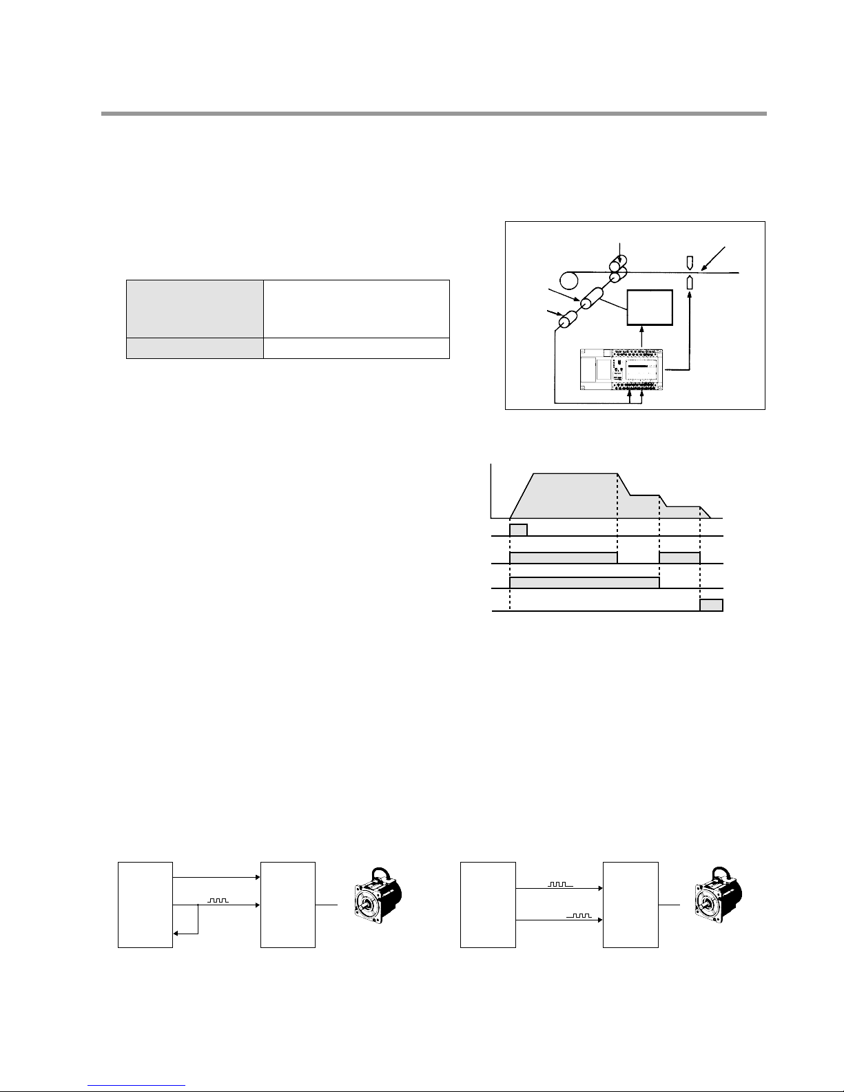
■ Pulse output function (transistor output type)
This function allows the output of a direct pulse (45 Hz to 4.9 k Hz) from the FP1. In combination with a drive, a
motor can be controlled. As direct pulse is possible, an additional positioning controller is not necessary. As the C56
and C72 series have two pulse outputs, they also support motor drives with one input for forward and the other input
for reverse driving. To prevent incorrect forward/reverse driving, create an interlock circuit outside of the FP1.
• Position control:
C56 and C72 series
These also support drives with two pulse inputs. In
addition, it is not necessary to connect the pulse
output to the high-speed counter (Y7 to X0).
C14, C16, C24, and C40 series
These support drives with one pulse input and one
direction switching input. When using a drive with
two pulse inputs, a switching circuit based on an
external relay is necessary.
Pulse
Frequency
Start
signal
"
"
"
Y0
Y1
Speed
signal
Stop
signal
This function allows the setting of a maximum of
eight output patterns with 15 level settings of the
high-speed counter. Can also be applied to multistage speed control with use of an inverter.
Max. counting speed
Counting range
1-phase: 10 k Hz
(when duty cycle ratio 50 %)
2-phase: 5 k Hz
–8,388,608 to 8,388,607
Motor Motor
Roller
Encoder
Motor
Start/Stop
signal
Cutter
Variable
motor
drive
Wire
Control
signal
FP1 Control Unit
CW/CCW
Y0
FP1
Control
Unit
Pulse
Y7
X0
High-speed counter
ON/OFF
Motor
drive
CW
Y6
FP1
Control
Uit
CCW
Y7
Motor
drive
3
1-1. Features
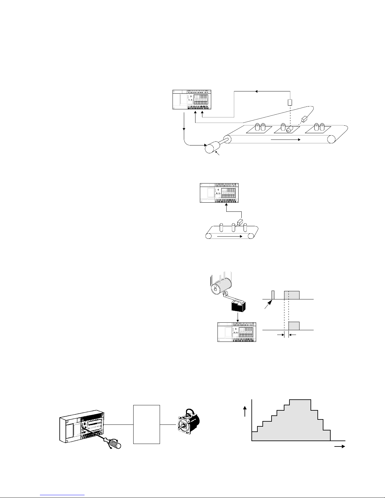
■ Interrupt input function (C24, C40, C56, and C72 series)
This function executes an interrupt program immediately after an external interrupt input (minimum pulse width of
0.2 ms) occurs, regardless of the input timing. It enables high-speed processing at a fixed timing and is not affected
by scan time. Therefore, it is useful when performing control which would be disrupted by variations in processing
time due to such factors as timing synchronization.
Timing control on a board inspection line
Immediately executes interrupt program
when an edge detection signal comes in by
interrupt input from Sensor 1. Sensor 2
inspects the part, and if an abnormality is
detected, the conveyor stops and the
abnormality is reported.
■ Pulse catch input function (all series)
This function catches input pulse signals
down to a minimum width of 0.5 ms. It is
effective for situations such as when the
sensor detects the moving target at a high
speed.
■ Adjustable input time filtering function (all series*)
This function allows the input response
time (input time constant) to be changed
within a range of 1 to 128 ms in
accordance with the input device
connected. This prevents input errors due
to such causes as limit switch chattering
noise.
* For E8 and E16 series, input response
time is fixed as 2 ms.
■ Manual dial-set register control function (all series)
This function makes it possible to change the values of special data registers DT9040 to 9043 within a range of 0 to
255 using the potentiometers on the front face of the Control Unit. Input settings involving analog-type numerical
data such as analog timer and pulse output frequency changes can be performed.
FP1 Control Unit
Sensor 2
Sensor 1
Interrupt input
signal
Stop signal
Motor
COM0COM1COM2COM3COM4COM5COM6COM
7
+-
24V DC
F.G.
COM
F89EABCD
(+)
-
COM
70162345
(+)
-
RUN
REMOTE
PROG.
V0
max.
min.
RUN
PROG.
ERR.
ALRAM
BATTERY
V1
max.
PC
FP1-C24
24V DC
+
-
min.
Sensor
FP1 Control Unit
COM0COM1COM2COM3COM4COM5COM6COM
7
+-
24V DC
F.G.
COM
F89EABCD
(+)
-
COM
70162345
(+)
-
RUN
REMOTE
PROG.
V0
max.
min.
RUN
PROG.
ERR.
ALRAM
BATTERY
V1
max.
PC
FP1-C24
24V DC
+
-
min.
Response time
Limit switch
FP1
FP1
Control
Unit
COM0COM1COM2COM3COM4COM5COM6COM
7
+-
24V DC
F.G.
COM
F89EABCD
(+)
-
COM
70162345
(+)
-
RUN
REMOTE
PROG.
V0
max.
min.
RUN
PROG.
ERR.
ALRAM
BATTERY
V1
max.
PC
FP1-C24
24V DC
+
-
min.
Limit
switch
f
Pulse
Motor
driver
Noise
is ignored
Motor
FP1 Control Unit

4
1-1. Features
■ Forced ON/OFF control function (all series)
This function allows the state of the input and output
contacts to be forced ON or OFF with a programming tool
(NPST-GR Software, etc.). By forcing the output contact
ON or OFF, the connection on the output side can be
checked. By forcing the input contact ON or OFF, the
program can be checked.
■ Password protection function (all series)
This function forbids reading and writing of the program and system registers. It can be used for program protection
and when secrecy is required.
■ Constant length scan setting function (all series)
The duration of one scan is fixed by setting it to units of 2.5 ms, eliminating variation in the scan time.
■ Clock/Calendar control function (C24C, C40C, C56C, and C72C types)
By means of year, month, day, hour, minute, second, and day of the week settings, this function makes it possible to
change temporal elements of control. It can be used for temporal control of such items as lighting, air conditioning,
and equipment.
COM0COM1COM2COM3COM4COM5COM6COM
7
+-
24V DC
F.G.
COM
F89EABCD
(+)
-
COM
70162345
(+)
-
RUN
REMOTE
PROG.
V0
max.
min.
RUN
PROG.
ERR.
ALRAM
BATTERY
V1
max.
PC
FP1-C24
24V DC
+
-
min.
FP1
Personal
computer
ON
ON
5
1-1. Features
2. Communication Functions
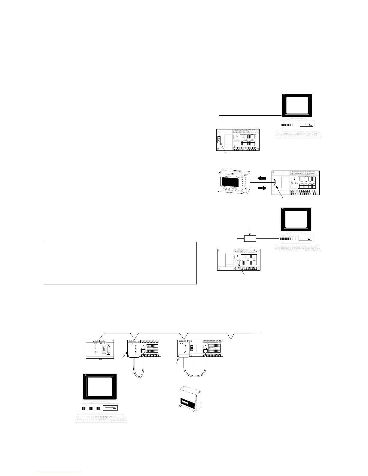
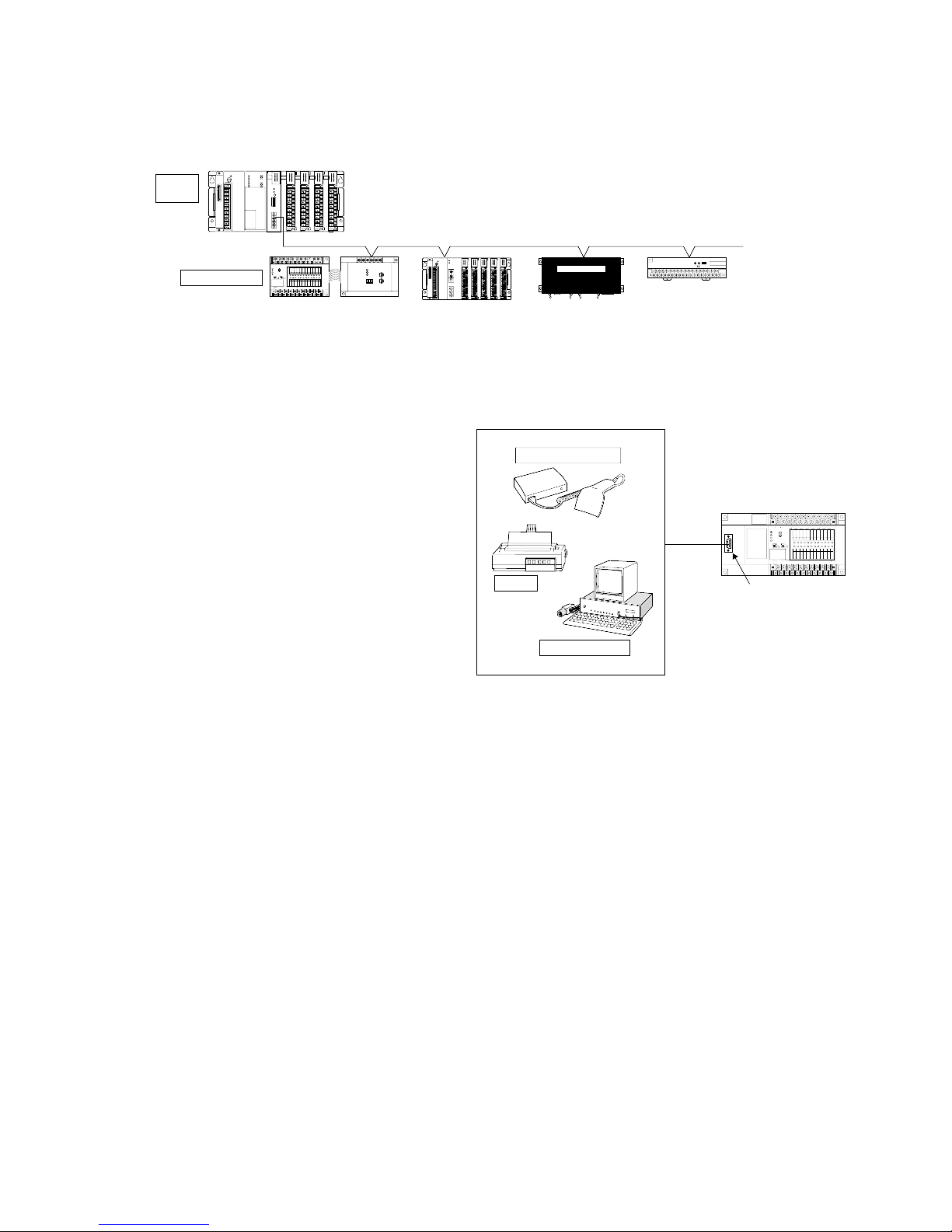
■ Computer link function (MEWTOCOL)
This function allows the reading and writing of FP1 contact information and data register content from a host
computer. It can be used for such applications as data collection and the monitoring of operating conditions.
Communication between one computer and one FP1 Control Unit
• Using RS232C port (C24C, C40C, C56C, and C72C types)
The RS232C port can be used for direct connection to a
personal computer, allowing the easy performance of a 1:1
computer link.
• Using programming tools connector (RS422 port) (all series)
The RS422 port can also be used for a 1:1 computer link by
connecting it through an RS422/232C Adapter.
Note:
Communication between one computer and 32 FP1 Control Units
Using a C-NET Adapter, a maximum of 32 FP1 units can be connected with one personal computer. If a bar code
reader is connected via the RS232C port, this system can be used for collection of various production control
information.
• Refer to C-NET LINK UNIT Technical Manual for details about computer link function.
COM0COM1COM2COM3COM4COM5COM6COM
7
+-
24V DC
F.G.
COM
F89EABCD
(+)
-
COM
70162345
(+)
-
RUN
REMOTE
PROG.
V0
max.
min.
RUN
PROG.
ERR.
ALRAM
BATTERY
V1
max.
24V DC
+
-
min.
FP1
Control Unit
PC
C-NET
ADAPTER
ON
OFF
ON
ON
ABCDEF
ABCDEFGHI
AB ABCD
PC
C-NET
ADAPTER
ON
OFF
ON
ON
ABCDEF
ABCDEFGHI
AB
COM0COM1COM2COM3COM4COM5COM6COM
7
+-
24V DC
F.G.
COM
F89EABCD
(+)
-
COM
70162345
(+)
-
RUN
REMOTE
PROG.
V0
max.
min.
RUN
PROG.
ERR.
ALRAM
V1
max.
24V DC
+
-
min.
PC
C-NET
ADAPTER
ON
OFF
ON
ON
ABCDEF
ABCDEFGHI
AB
A
B
C
D
E
F
G
H
I
A
B
C
D
E
F
G
H
I
A
B
C
D
E
F
G
H
I
A
B
CD
E
F
G
H
I
AB
Bar code reader
Personal
computer
C-NET
Adapter
standard
type
FP1
Control Unit
C-NET
Adapter
S1 type
C-NET
Adapter
S1 type
A maximum of 32 FP1s
can be connected.
When using control units equipped with RS232C port
(C24C, C40C, C56C, and C72C types), various
combinations can be created by making a computer
link through the RS422 port and connecting another
device to the RS232C port.
When connected to an I.O.P. using the computer link
function, the I.O.P.’s data can be read as the FP1’s
internal relay or data register data. This can be used
for such operations as production control.
FP1 Control Unit
RS232C port
COM0COM1COM2COM3COM4COM5COM6COM
7
+-
24V DC
F.G.
COM
F89EABCD
(+)
-
COM
70162345
(+)
-
RUN
REMOTE
PROG.
V0
max.
min.
RUN
PROG.
ERR.
ALRAM
BATTERY
V1
max.
PC
FP1-C24
24V DC
+
-
min.
Personal computer
FP1
Control Unit
Programming tools
connector (RS422 port)
COM0COM1COM2COM3COM4COM5COM6COM
7
+-
24V DC
F.G.
COM
F89EABCD
(+)
-
COM
70162345
(+)
-
RUN
REMOTE
PROG.
V0
max.
min.
RUN
PROG.
ERR.
ALRAM
BATTERY
V1
max.
PC
FP1-C24
24V DC
+
-
min.
Personal computer
RS232CRS422
RS422/232C Adapter
a
b
c
d
I.O.P.
a
b
c
d
a
b
c
d
FP1 Control Unit
BATTERY
RUN
PROG.
ERR.
ALRAM
min.
FP1-C24
24V DC
RS232C port
+-
24V DC
F.G.
RUN
REMOTE
PROG.
max.
max.
min.
V0
V1
PC
-
COM
(+)
-
+
COM0COM1COM2COM3COM4COM5COM6COM
COM
(+)
F89EABCD
-
7
70162345
6
1-1. Features
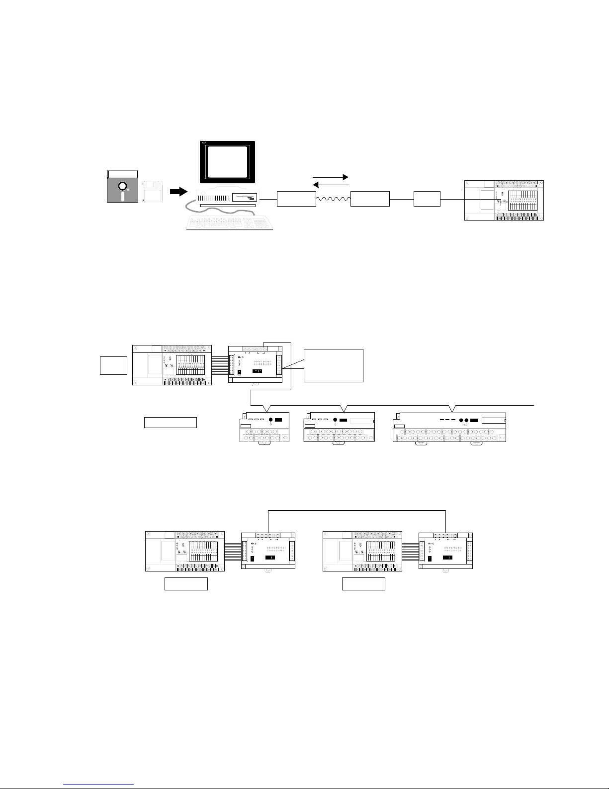
■ Modem communication (C24, C40, C56, and C72 series)
Using a modem, data transfer and long-distance communication between a personal computer and an FP1 unit can
be performed. This can be done even when using NPST-GR Software. Select a cable in accordance with the
specifications of the modem used.
■ MEWNET-TR (Remote I/O Control) system
I/O information can be exchanged between a master and several slave stations at a remote site. A maximum of 80
inputs and 64 outputs can be controlled by 2 master units (C24, C40, C56 and C72 series) one transmitter master
unit supports a total communication distance of 700 m using twisted pair cable. Master to master communication is
also available.
• Master-slave communication
• Master-master communication
COM0COM1COM2COM3COM4COM5COM6COM
7
+-
24V DC
F.G.
COM
F89EABCD
(+)
-
COM
70162345
(+)
-
RUN
REMOTE
PROG.
V0
max.
min.
RUN
PROG.
ERR.
ALRAM
BATTERY
V1
max.
PC
FP1-C24
24V DC
+
-
min.
FP1 Control Unit
F.G. +-F.G.+-
24V DC
RS485
POWER
COM.
ALARM
TRNET
MODE SW.
ON
OFF
1
23456
Matsushita Electric Works, Ltd.
MONITOR SW.
INPUT UNIT
OUTPUT UNIT
0
7123456
8
F9ABCDE
FP1 Transmitter
Master Unit
Master A
COM0COM1COM2COM3COM4COM5COM6COM
7
+-
24V DC
F.G.
COM
F89EABCD
(+)
-
COM
70162345
(+)
-
RUN
REMOTE
PROG.
V0
max.
min.
RUN
PROG.
ERR.
ALRAM
BATTERY
V1
max.
PC
FP1-C24
24V DC
+
-
min.
FP1 Control Unit
F.G. +-F.G.+-
24V DC
RS485
POWER
COM.
ALARM
TRNET
MODE SW.
ON
OFF
1
23456
Matsushita Electric Works, Ltd.
MONITOR SW.
INPUT UNIT
OUTPUT UNIT
0
7123456
8
F9ABCDE
FP1 Transmitter
Master Unit
Master B
Twisted pair cable or 2-conductor cable
COM0COM1COM2COM3COM4COM5COM6COM
7
+-
24V DC
F.G.
COM
F89EABCD
(+)
-
COM
70162345
(+)
-
RUN
REMOTE
PROG.
V0
max.
min.
RUN
PROG.
ERR.
ALRAM
BATTERY
V1
max.
PC
FP1-C24
24V DC
+
-
min.
FP1 Control Unit
F.G. +-F.G.+-
24V DC
RS485
POWER
COM.
ALARM
TRNET
MODE SW.
ON
OFF
1
23456
Matsushita Electric Works, Ltd.
MONITOR SW.
INPUT UNIT
OUTPUT UNIT
0
7123456
8
F9ABCDE
FP1 Transmitter Master Unit
I/O Transmitter
Unit (4-point)
Master
station
Slave stations
NAIS FP I/O TRANSMITTER UNIT
4-OUTPUT (T1 O.5 A NPN) AFP87527
ab ab ab ab
Matsushita
Electronic Works, Ltd
POWER COM. ALARM
TRNET
I/O Transmitter
Unit (8-point)
I/O Transmitter
Unit (16-point)
Max. 700 m with twisted pair cable
NAIS FP I/O TRANSMITTER UNIT 16-OUTPUT (T1 O.5 A NPN) AFP87524
ab ab ab ab ab ab ab ab ab ab ab ab ab ab ab ab
Matsushita Electronic Works, Ltd
POWER COM. ALARM
TRNET
NAIS FP I/O TRANSMITTER UNIT 8-INPUT (24 V DC) AFP87521
ab ab ab ab ab ab ab ab
Matsushita Electronic Works, Ltd
POWER COM. ALARM
TRNET
When shipped,
32 inputs
32 output
FP1 Control Unit
COM0COM1COM2COM3COM4COM5COM6COM
7
+-
24V DC
F.G.
COM
F89EABCD
(+)
-
COM
70162345
(+)
-
RUN
REMOTE
PROG.
V0
max.
min.
RUN
PROG.
ERR.
ALARM
BATTERY
V1
max.
PC
FP1-C24
24V DC
+
-
min.
Personal computer
NPST-GR Software
Modem Modem
Public telephone line
RS422/232C
Adapter
7
1-1. Features
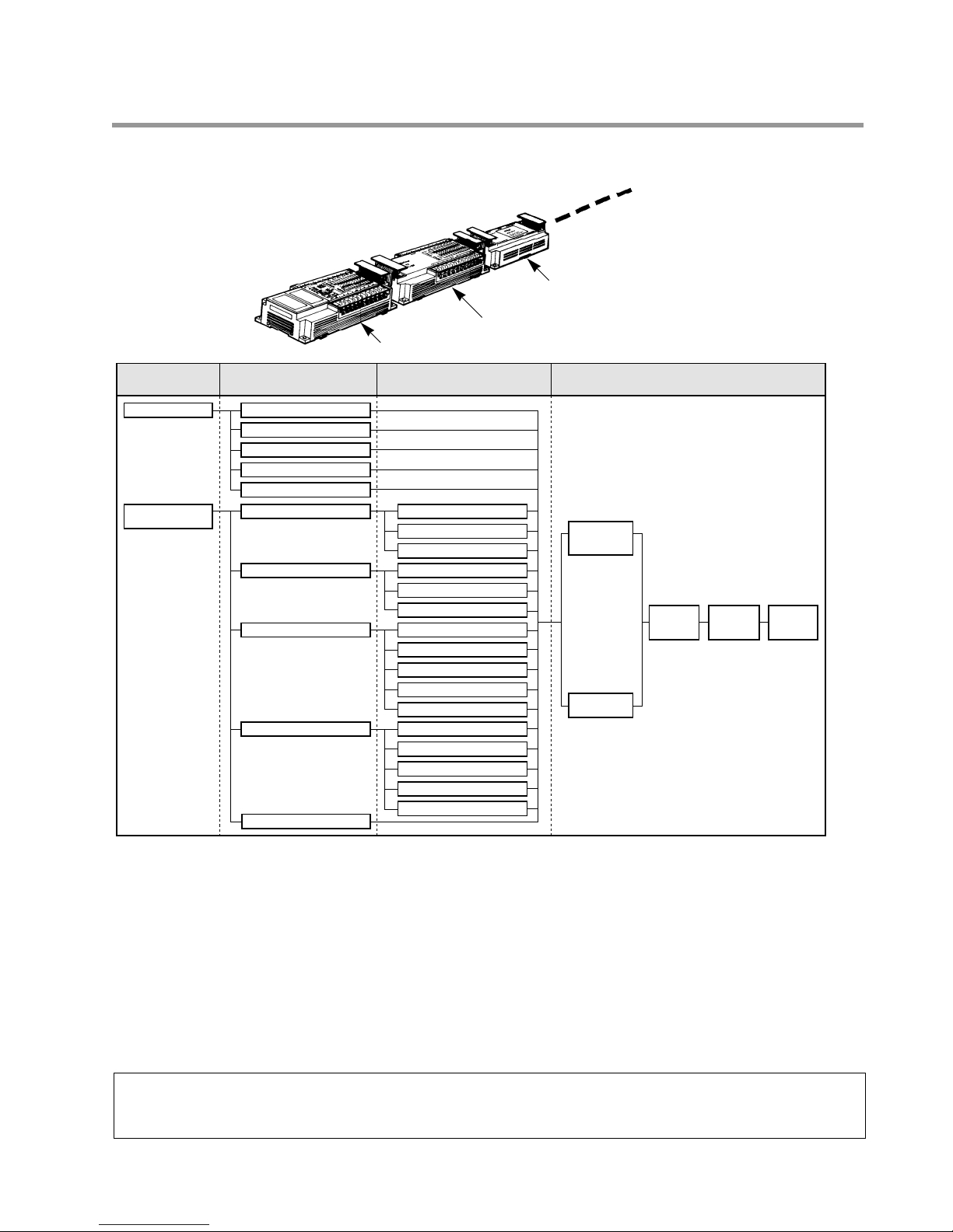
■ MEWNET-F (Remote I/O Control) system
Using a FP1 I/O link unit, this function allows the exchange of I/O information with the host FP series
programmable controller through a two-conductor cable.
• Refer to REMOTE I/O SYSTEM Technical Manual for details about I/O link function (remote I/O control
function).
■ General communication using RS232C port (C24C, C40C, C56C, and C72C types)
COM0COM1COM2COM3COM4COM5COM6COM
7
+-
24V DC
F.G.
COM
F89EABCD
(+)
-
COM
70162345
(+)
-
RUN
REMOTE
PROG.
V0
max.
min.
RUN
PROG.
ERR.
ALRAM
BATTERY
V1
max.
PC
FP1-C24
24V DC
+
-
min.
FP1 Control Unit
RS232C port
National
abc
abc
abc
a
b
c
Bar-code reader
Printer
Image checker
This function allows data input and output
when connected to a device having an RS232C
port. Data reading from a bar code reader, data
output to a printer, and bilateral data exchange
with the image checker are all possible.
ABCDE
AB
ABC
ABCDE
AB
AB
AB
PC
FP!
I/OLINK
ABC
AB
National FP I/O TERMINAL BOARD
ABCDEFGHIJ ABCDEFGHIJ ABCDEFGHIJ
ABCDEFGHIJ ABCDEFGHIJ
National
ab ab ab ab ab ab ab ab ab ab ab ab ab ab ab ab
ab ab ab
ab
abcdefg abcdefg
COM0COM1COM2COM3COM4COM5COM6COM
7
+-
24V DC
F.G.
COM
F89EABCD
(+)
-
COM
70162345
(+)
-
RUN
REMOTE
PROG.
V0
max.
min.
RUN
PROG.
ERR.
ALRAM
V1
max.
PC
FP1-C24
24V DC
+
-
min.
Master Unit
FP1
Control Unit
FP1 I/O
Link Unit
FP I/O
Terminal Board
FP I/O
Terminal Unit
Slave Unit
Master
station
Slave stations
FP3 or FP5
POWER CPU
National
FP3
POWER
FP3 or FP5

8
1-2. Table of FP1 Units
1-2. Table of FP1 Units
1. Control Units
C14
C16
C24
Description
EEPROM
EEPROM
RAM
RAM
14
Input: 8
Output: 6
16
Input: 8
Output: 8
24
Input: 16
Output: 8
24
Input: 16
Output: 8
Operating
voltage
24 V DC
100 V to
240 V AC
24 V DC
100 V to
240 V AC
24 V DC
100 V to
240 V AC
24 V DC
100 V to
240 V AC
Input type
Relay
Transistor (NPN open collector)
Transistor (PNP open collector)
Relay
Transistor (NPN open collector)
Transistor (PNP open collector)
Relay
Transistor (NPN open collector)
Transistor (PNP open collector)
Relay
Transistor (NPN open collector)
Relay
Transistor (NPN open collector)
Transistor (PNP open collector)
Relay
Transistor (NPN open collector)
Relay
Transistor (NPN open collector)
Transistor (PNP open collector)
Relay
Transistor (NPN open collector)
Relay
Transistor (NPN open collector)
Transistor (PNP open collector)
Relay
Transistor (NPN open collector)
Relay
Transistor (NPN open collector)
Transistor (PNP open collector)
Relay
Transistor (NPN open collector)
Relay
Transistor (NPN open collector)
Transistor (PNP open collector)
Relay
Transistor (NPN open collector)
Part number
AFP12313B
AFP12343B
AFP12353B
AFP12317B
AFP12347B
AFP12357B
AFP12113B
AFP12143B
AFP12153B
AFP12112B
AFP12142B
AFP12117B
AFP12147B
AFP12157B
AFP12116B
AFP12146B
AFP12213B
AFP12243B
AFP12253B
AFP12212B
AFP12242B
AFP12217B
AFP12247B
AFP12257B
AFP12216B
AFP12246B
AFP12213CB
AFP12243CB
AFP12253CB
AFP12212CB
AFP12242CB
AFP12217CB
AFP12247CB
AFP12257CB
AFP12216CB
AFP12246CB
Sink/source
Sink/source
Sink/source
Source
Sink/source
Source
Sink/source
Source
Sink/source
Source
Sink/source
Source
Sink/source
Source
Standard
types
Standard
types
Standard
types
C24C types
(with
RS232C
port and
Clock/
Calender
function)
Series
Built-in
memory
I/O point
Output type

9
1-2. Table of FP1 Units
C40
C56
C72
RAM
RAM
RAM
RAM
RAM
RAM
40
Input: 24
Output: 16
40
Input: 24
Output: 16
56
Input: 32
Output: 24
56
Input: 32
Output: 24
72
Input: 40
Output: 32
72
Input: 40
Output: 32
24 V DC
100 V to
240 V AC
24 V DC
100 V to
240 V AC
24 V DC
100 V to
240 V AC
24 V DC
100 V to
240 V AC
24 V DC
100 V to
240 V AC
24 V DC
100 V to
240 V AC
Relay
Transistor (NPN open collector)
Transistor (PNP open collector)
Relay
Transistor (NPN open collector)
Relay
Transistor (NPN open collector)
Transistor (PNP open collector)
Relay
Transistor (NPN open collector)
Relay
Transistor (NPN open collector)
Transistor (PNP open collector)
Relay
Transistor (NPN open collector)
Relay
Transistor (NPN open collector)
Transistor (PNP open collector)
Relay
Transistor (NPN open collector)
Relay
Transistor (NPN open collector)
Transistor (PNP open collector)
Relay
Transistor (NPN open collector)
Transistor (PNP open collector)
Relay
Transistor (NPN open collector)
Transistor (PNP open collector)
Relay
Transistor (NPN open collector)
Transistor (PNP open collector)
Relay
Transistor (NPN open collector)
Transistor (PNP open collector)
Relay
Transistor (NPN open collector)
Transistor (PNP open collector)
Relay
Transistor (NPN open collector)
Transistor (PNP open collector)
Relay
Transistor (NPN open collector)
Transistor (PNP open collector)
AFP12413B
AFP12443B
AFP12453B
AFP12412B
AFP12442B
AFP12417B
AFP12447B
AFP12457B
AFP12416B
AFP12446B
AFP12413CB
AFP12443CB
AFP12453CB
AFP12412CB
AFP12442CB
AFP12417CB
AFP12447CB
AFP12457CB
AFP12416CB
AFP12446CB
AFP12513B
AFP12543B
AFP12553B
AFP12517B
AFP12547B
AFP12557B
AFP12513CB
AFP12543CB
AFP12553CB
AFP12517CB
AFP12547CB
AFP12557CB
AFP12713B
AFP12743B
AFP12753B
AFP12717B
AFP12747B
AFP12757B
AFP12713CB
AFP12743CB
AFP12753CB
AFP12717CB
AFP12747CB
AFP12757CB
Sink/source
Source
Sink/source
Source
Sink/source
Source
Sink/source
Source
Sink/source
Sink/source
Sink/source
Sink/source
Sink/source
Sink/source
Sink/source
Sink/source
Standard
types
C40C types
(with
RS232C
port and
Clock/
Calender
function)
Standard
types
C56C types
(with RS232C
port and
Clock/
Calender
function)
Standard
types
C72C types
(with RS232C
port and
Clock/
Calender
function)
Description
Operating
voltage
Input type
Part number
Series
Built-in
memory
I/O point
Output type

10
1-2. Table of FP1 Units
2. Expansion Units
E8
E16
E24
E40
8
Input: 8
8
Input: 4
Output: 4
8
Output: 8
16
Input: 16
16
Input: 8
Output: 8
16
Output: 16
24
Input: 16
Output: 8
40
Input: 24
Output: 16
24 V DC
100 V to
240 V AC
24 V DC
100 V to
240 V AC
Relay
Transistor (NPN open collector)
Relay
Transistor (NPN open collector)
Transistor (PNP open collector)
Relay
Transistor (NPN open collector)
Transistor (PNP open collector)
Triac
Relay
Transistor (NPN open collector)
Relay
Transistor (NPN open collector)
Transistor (PNP open collector)
Relay
Transistor (NPN open collector)
Relay
Transistor (NPN open collector)
Relay
Transistor (NPN open collector)
Transistor (PNP open collector)
Relay
Transistor (NPN open collector)
Relay
Transistor (NPN open collector)
Transistor (PNP open collector)
Relay
Transistor (NPN open collector)
Relay
Transistor (NPN open collector)
Transistor (PNP open collector)
Relay
Transistor (NPN open collector)
Relay
Transistor (NPN open collector)
Transistor (PNP open collector)
AFP13802
AFP13803
AFP13812
AFP13842
AFP13813
AFP13843
AFP13853
AFP13810
AFP13840
AFP13850
AFP13870
AFP13103
AFP13112
AFP13142
AFP13113
AFP13143
AFP13153
AFP13110
AFP13140
AFP13212
AFP13242
AFP13213
AFP13243
AFP13253
AFP13216
AFP13246
AFP13217
AFP13247
AFP13257
AFP13412
AFP13442
AFP13413
AFP13443
AFP13453
AFP13416
AFP13446
AFP13417
AFP13447
AFP13457
Source
Sink/source
Source
Sink/source
Sink/source
Source
Sink/source
Source
Sink/source
Source
Sink/source
Source
Sink/source
Source
Sink/source
Description
Operating
voltage
Input type
Part number
Series
I/O point
Output type

3. Intelligent Units
4. Link Units
FP1 Transmitter
Master Unit
FP1 I/O Link Unit
C-NET Adapter
C-NET Adapter S1 type
(for FP1 Control Unit only)
Operating voltage
24 V DC
100 V to
240 V AC
24 V DC
100 V to
240 V AC
24 V DC
100 V to
240 V AC
Part number
AFP1752
AFP1756
AFP1732
AFP1736
AFP8532
AFP8536
AFP15401
Type Specification
FP1 Transmitter Master Unit enables the FP1 to
exchange I/O information with slave stations at a
remote site using a twisted pair cable. By connecting
with another FP1 Transmitter Master Unit or with an
FP3 Transmitter Master Unit, you can exchange I/O
information with another FP1. Communication
medium (RS485 port): Twisted pair cable up to 32
inputs and 32 outputs can be controlled per unit.
The FP1 I/O Link Unit is the interface unit for
exchanging I/O information between an FP3/FP5
and an FP1.
When the FP1 is connected to the FP3/FP5 Remote
I/O System via the FP1 I/O Link Unit, you can
exchange I/O information serially, using a
2-conductor cable.
RS485 ↔ RS422/RS232C signal converter
Used for communication between the Programmable
Controller and your computer.
Communication medium (RS485 port): 2-conductor
cable or twisted pair cable
RS485 ↔ RS422 signal converter for FP1 Control
Unit.
Used for communication between the C-NET
Adapter and FP1 Control Unit.
FP1 A/D Converter Unit
FP1 D/A Converter Unit
• Analog input points:
• Analog input range:
• Digital output range:
• Analog output points:
• Analog output range:
• Digital input range:
24 V DC
100 V to
240 V AC
24 V DC
100 V to
240 V AC
AFP1402
AFP1406
AFP1412
AFP1416
4 channels/unit
0 to 5 V, 0 to 10 V,
0 to 20 mA
K0 to K1000
2 channels/unit
0 to 5 V, 0 to 10 V,
0 to 20 mA
K0 to K1000
Type Specification Operating voltage Part number
11
1-2. Table of FP1 Units
12
1-3. Expansion and Configurations
1-3. Expansion and Configurations
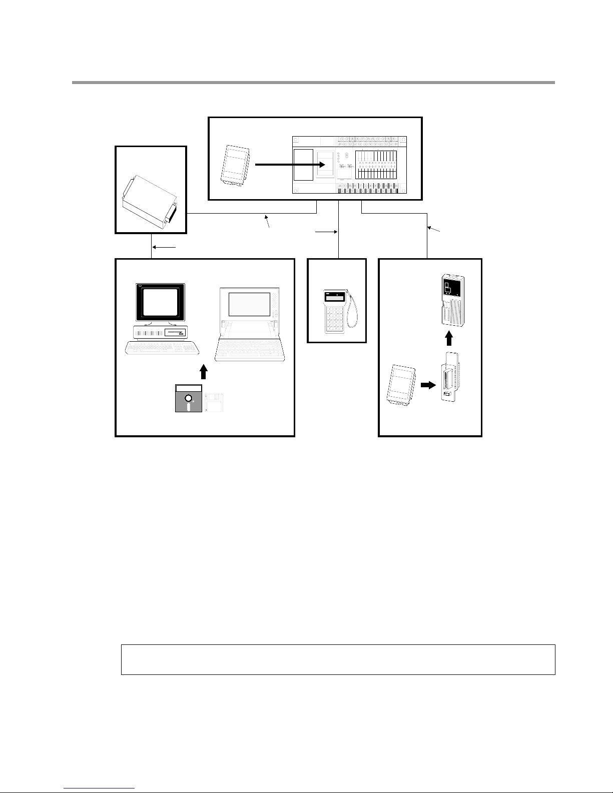
1. Expansion of Units
Be sure to check that the units are expanded according to the following restrictions:
1) Expansion Units
Note:
• Expansion units (E8 and E16 series) which do not require power supply cannot be connected in
succession. For this reason, when an E8 series or an E16 series is used as a primary expansion unit, it
can only be combined with E24 or E40 series as secondary expansion unit.
■ Control Units (C24, C40, C56 or C72 series)
• Number of expandable units: Max. 2 units
• Total number of I/O points:
C24 series: Max. 104 points
C40 series: Max. 120 points
C56 series: Max. 136 points
C72 series: Max. 152 points
■ Control Units (C14 and C16 series)
• Number of expandable units: 1 unit
• Total number of I/O points:
C14 series: Max. 54 points
C16 series: Max. 56 points
C14 or C16 series E8 series
E16 series
E24 series
E40 series
E8 series
E16 series
E24 series
E40 series
E24 series
E40 series
E24 series
E40 series
E8 series
E16 series
E24 series
E40 series
E8 series
E16 series
E24 series
E40 series
FP1 D/A
Converter
Unit
FP1 D/A
Converter
Unit
C24, C40, C56 or
C72 series
FP1 I/O
Link Unit
One unit
FP1 A/D
Converter
Unit
One unit
or
Control Unit
Primary
Expansion Unit
Secondary
Expansion Unit
Intelligent Unit and Link Unit
FP1
Transmitter
Master Unit
FP1 Transmitter Master Unit
FP1 Transmitter Master Unit
FP1 Transmitter Master Unit
FP1 Transmitter Master Unit
FP1 Transmitter Master Unit
FP1 Transmitter Master Unit
Control Unit
Expansion Unit
Intelligent Unit
Example:

13
1-3. Expansion and Configurations
2) Intelligent Units and Link Unit
• Number of expandable units together:
FP1 A/D Converter Unit: 1 unit; FP1 D/A Converter Unit: 2 units; FP1 Transmitter Master Unit and FP1 I/O Link Unit:
1 of each unit; FP1 I/O Link Unit: 1 unit
• There are no restrictions on the order of connection of intelligent units and link unit.
2. Combination of Units
14
16
22
24
30
32
38
40
48
54
56
8
8
8
12
16
16
8
12
16
8
16
24
8
16
24
16
20
24
24
24
24
16
24
32
32
24
28
32
32
32
32
32
36
40
24
32
40
6
8
14
10
6
8
16
12
8
22
14
6
24
16
8
16
12
8
14
16
16
24
16
8
16
24
20
16
22
24
24
24
20
16
32
24
16
C14
C16
C14
C24
C16
C14
C16
C24
C14
C40
C16
C24
C24
C40
C14
C56
C16
C24
C40
8
8
8
8
8
16
8
8
8
8
8
8
8
8
8
16
16
16
8
24
8
16
16
16
16
24
24
24
8
32
8
16
16
16
24
24
24
6
8
6
6
6
8
8
8
8
6
6
6
8
8
8
8
8
8
6
16
8
8
8
8
8
16
16
16
6
24
8
8
8
8
16
16
16
E8
E8
E16
E16
E8
E24
E24
E16
E24
E8
E40
E40
E24
E16
0
4
8
0
4
8
0
8
16
0
8
16
0
4
8
16
16
0
8
16
16
0
4
8
24
24
16
16
16
0
8
16
8
4
0
8
4
0
16
8
0
16
8
0
8
4
0
8
8
16
8
0
8
8
4
0
16
16
8
8
8
16
8
0
E8 0
4
8
8
4
0
Total Input Output Series Input Output Series Input Output Series Input Output
Requested I/O point Control Unit Primary Expansion Unit
Secondary Expansion Unit

14
1-3. Expansion and Configurations
64
72
80
88
40
32
40
48
40
32
36
40
40
48
40
44
48
40
44
48
32
40
48
40
48
56
48
40
48
56
48
40
44
48
56
56
48
52
56
48
52
56
40
48
56
24
32
24
16
24
32
28
24
32
24
32
28
24
32
28
24
40
32
24
40
32
24
32
40
32
24
32
40
36
32
32
32
40
36
32
40
36
32
48
40
32
C24
C40
C56
C72
C24
C40
C56
C24
C40
C56
C72
C24
C40
C56
C72
16
16
16
16
24
32
32
32
40
16
16
16
16
24
24
24
32
32
32
16
16
16
24
24
24
24
32
40
40
40
16
24
24
24
24
32
32
32
40
40
40
8
8
8
8
16
24
24
24
32
8
8
8
8
16
16
16
24
24
24
8
8
8
16
16
16
16
24
32
32
32
8
16
16
16
16
24
24
24
32
32
32
E40
E24
E24
E8
E24
E40
E24
E16
E40
E40
E24
E24
E8
E40
E24
E40
E24
E16
24
16
16
16
16
0
4
8
16
24
24
24
16
16
16
0
8
16
24
24
24
24
16
16
16
16
0
4
8
24
16
24
24
24
16
16
16
0
8
16
16
8
8
8
8
8
4
0
8
16
16
16
8
8
8
16
8
0
16
16
16
16
8
8
8
8
8
4
0
16
8
16
16
16
8
8
8
16
8
0
Total Input Output Series Input Output Series Input Output Series Input Output
Requested I/O point Control Unit Primary Expansion Unit
Secondary Expansion Unit
E16
E24
E8
E8
E16
E16
E24
E24
E8
E8
0
8
16
16
0
4
8
0
4
8
0
8
16
0
8
16
16
16
0
4
8
0
4
8
16
8
0
8
8
4
0
8
4
0
16
8
0
16
8
0
8
8
8
4
0
8
4
0

15
1-3. Expansion and Configurations
96
104
112
120
128
136
152
48
56
64
56
48
56
64
56
64
64
64
56
60
64
56
60
64
56
64
72
64
56
64
72
72
72
72
64
68
72
64
72
80
80
80
88
48
40
32
40
48
40
32
40
40
40
40
48
44
40
48
44
40
56
48
40
48
56
48
40
48
48
48
56
52
48
64
56
48
56
56
64
C40
C56
C72
C24
C40
C56
C72
C56
C72
C40
C56
C72
C72
C56
C72
C72
24
24
24
32
32
32
32
40
16
24
32
32
32
32
40
40
40
32
32
32
40
40
40
40
24
32
40
40
40
40
40
40
40
32
40
40
16
16
16
24
24
24
24
32
8
16
24
24
24
24
32
32
32
24
24
24
32
32
32
32
16
24
32
32
32
32
32
32
32
24
32
32
E40
E40
E24
E24
E40
E40
E24
E40
E24
E40
E40
E24
E40
E40
E24
E40
E40
E40
E40
E40
24
24
24
24
16
16
16
16
24
24
16
24
24
24
16
16
16
24
24
24
24
16
16
16
24
24
16
24
24
24
24
24
24
24
24
24
16
16
16
16
8
8
8
8
16
16
8
16
16
16
8
8
8
16
16
16
16
8
8
8
16
16
8
16
16
16
16
16
16
16
16
16
Total Input Output Series Input Output Series Input Output Series Input Output
Requested I/O point Control Unit Primary Expansion Unit
Secondary Expansion Unit
E16
E16
E40
E24
E24
E8
E8
E16
E16
E40
E24
E24
E8
E16
E40
E24
E40
0
8
16
0
8
16
24
16
16
0
4
8
0
4
8
0
8
16
0
8
16
24
16
16
0
4
8
0
8
16
24
16
24
16
8
0
16
8
0
16
8
8
8
4
0
8
4
0
16
8
0
16
8
0
16
8
8
8
4
0
16
8
0
16
8
16
16
1-4. Programming Tools
1-4. Programming Tools
■ System Configurations of Programming Tools
1. Programming Tools
Program editing can be done with a commercially available personal computer and FP Programmer II.
1) NPST-GR Software
Using the NPST-GR program editing software, programs can be easily created with any personal computer on hand.
Necessary tools
• Computer: Commercially available personal computer (IBM PC-AT or 100% compatible machine)
System required:
- Main memory: 550 KB or more free
- EMS: 800 KB or more free
- Hard disk space: 2 MB or more
- Operating System: MS-DOS Ver. 3.30 or later
- Video mode (Display mode): EGA or VGA
• NPST-GR Software Ver. 3: AFP266538
Note:
• RS232C cable (3 m / 9.843 ft.): AFB85833/AFB85853
• RS422/232C Adapter: AFP8550
• FP1 Peripheral Cable:
0.5 m / 1.640 ft.: AFP15205
3 m / 9.843 ft.: AFP1523
• The .EXE files in NPST-GR Software are compressed in the system disks. When installing
NPST-GR, you will have to expand them.
COM0COM1COM2COM3COM4COM5COM6COM
7
+-
24V DC
F.G.
COM
F89EABCD
(+)
-
COM
70162345
(+)
-
RUN
REMOTE
PROG.
V0
max.
min.
RUN
PROG.
ERR.
ALRAM
BATTERY
V1
max.
PC
FP1-C24
24V DC
+
-
min.
FP1 Control Unit
NPST-GR Software
FP
Programmer II
Commercially available personal computer
(IBM PC-AT or 100% compatible)
F
P
1
M
E
M
O
R
Y
U
N
IT
M
A
T
U
S
IT
A
E
L
E
C
T
R
I
C
W
O
R
K
S
.
L
T
D
M
A
D
E
IN
J
A
P
A
N
F
P
1
M
E
M
O
R
Y
U
N
IT
M
A
T
U
S
IT
A
E
L
E
C
T
R
IC
W
O
R
K
S
.
LT
D
M
A
D
E
IN
JA
P
A
N
N
a
tion
a
l
abcdefg
abcdefg
abcdefg
abcdefg
abcdefg
F
P
1
M
E
M
O
R
Y
U
N
IT
M
A
T
U
S
IT
A
E
L
E
C
T
R
IC
W
O
R
K
S
. L
T
D
M
A
D
E
IN
J
A
P
A
N
FP ROM Writer
Memory
(EPROM)
FP ROM Writer
Socket Adapter
Master Memory
(EEPROM)
PC
RS422/232C ADAPTER
Matsushita Electric Works, Ltd.
Made in Japan
• POWER
• TXD(
–)
• RXD(
–)
R
S
4
2
2
R
S
2
3
2
C
RS422/232C
Adapter
FP1
Peripheral Cable
FP1 Peripheral Cable
RS232C cable
FP PROGRAMMER
ST
X•WXANY•WYORR•WROTL•WL
FN/P
FL
NOT
DT/Ld
STK
IX/IY
TM
T•SV
CT
C•EV
(BIN)
K/H
=
CDD<E>F
SHIFT
SC
89AB
4 5 6 7
0 1 2 3
(-)
OP
SRC
READ
(HELP)
CLR
ACLR
(DELT)
INST
ENT
WRT
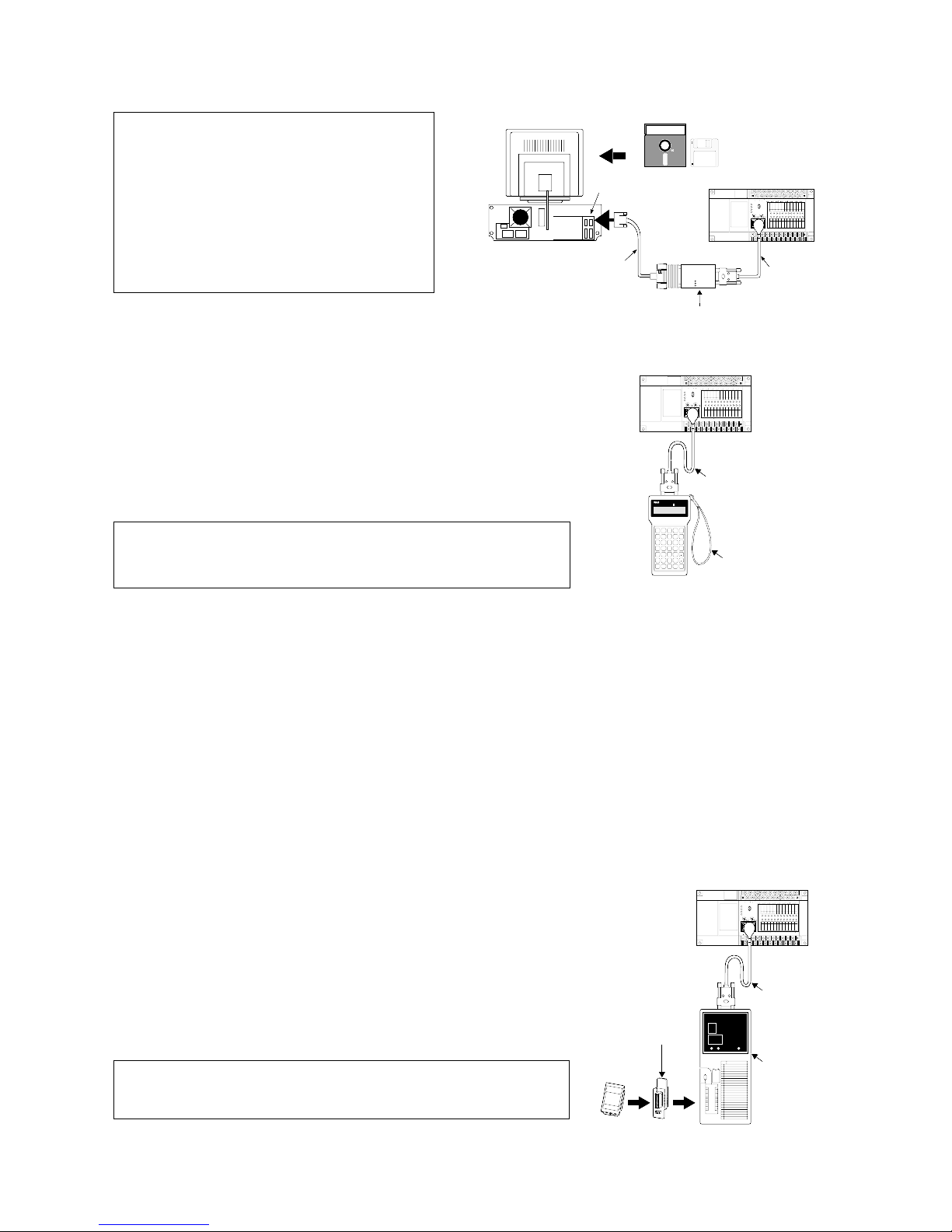
17
1-4. Programming Tools
Notes:
2) FP Programmer II
With the hand-held FP Programmer II, such operations as writing, reading,
and retrieval of programs can be performed.
Necessary tools
• FP1 Peripheral Cable:
0.5 m / 1.640 ft.: AFP15205
3 m / 9.843 ft.: AFP1523
• FP Programmer II: AFP1114
Note:
2. How to Program ROM
• Using an FP ROM Writer or a commercially available ROM programmer, the contents of the FP1’s internal RAM
can be written to ROM (memory).
• The following types of ROM (memory) are available:
- Memory (EPROM): AFP1201
Memory for storing programs. Writing is done with an FP ROM Writer or a commercially available ROM
writer.
- Master Memory (EEPROM): AFP1202 (for C24 and C40 series), AFP1203 (for C56 and C72 series)
Memory for copying programs. Writing is done with a master memory attached to the FP1 Control Unit.
■ Writing a program to the memory (EPROM) with an FP ROM Writer
[FP1’s internal RAM Memory]
The content of the FP1’s internal RAM is written directly to the
memory (EPROM).
Necessary tools
• FP1 Peripheral Cable:
0.5 m / 1.640 ft.: AFP15205
3 m / 9.843 ft.: AFP1523
• FP ROM Writer: AFP5651
• Socket adapter for FP ROM Writer:AFP1810
• Memory (EPROM): AFP1201
Note:
• Refer to page 86, “4-5. Memory Unit Creation and ROM
Operation” and “FP ROM WRITER Technical Manual”, for
details about programming ROM.
• Refer to page 86, “4-5. Memory Unit Creation and ROM
Operation” and “FP PROGRAMMER II Operation Manual”, for
details about writing programs using the FP Programmer II.
• Refer to page 86, “4-5. Memory Unit
Creation and ROM Operation” and “NPSTGR Manual”, for details about writing
programs using the NPST-GR Software.
• Refer to page 260, “8-10. Product Types”,
for details about RS232C cable wiring.
• When using NPST-GR Software Ver. 2,
refer to page 241, “1. Differences Between
NPST-GR Ver. 2.4 and Ver. 3.1.”
Commercially available
personal computer
(IBM PC-AT or 100% compatible)
RS232C interface
Rear view
RS232C cable
NPST-GR Software
FP1 Control Unit
National
RS422/232C ADAPTER
AFP8536
RS422
MATUSITA ELECTRIC WORKS. LTD
MADE IN JAPAN
RS232C
POWER
TXD(-)
RXD(-)
RS422/232C Adapter
BATTERY
COM0COM1COM2COM3COM4COM5COM6COM
+-
24V DC
F.G.
RUN
RUN
REMOTE
PROG.
PROG.
ERR.
ALRAM
max.
max.
min.
min.
V0
V1
-
COM
24V DC
(+)
-
+
7
COM
(+)
70162345
F89EABCD
-
FP1 Peripheral
Cable
FP1 Control Unit
BATTERY
COM0COM1COM2COM3COM4COM5COM6COM
+-
24V DC
F.G.
RUN
RUN
REMOTE
PROG.
PROG.
ERR.
ALRAM
max.
max.
min.
min.
V0
V1
-
COM
COM
24V DC
(+)
(+)
F89EABCD
-
-
+
7
70162345
FP PROGRAMMER
ST
X•WXANY•WYORR•WROTL•WL
NOT
DT/Ld
=
CDD<E>F
89AB
4 5 6 7
0 1 2 3
(HELP)
CLR
STK
IX/IY
ACLR
FN/P
FL
TM
CT
(BIN)
T•SV
C•EV
K/H
SHIFT
SC
(-)
OP
SRC
READ
(DELT)
ENT
WRT
INST
FP1
Peripheral Cable
FP Programmer II
Socket adapter
for FP ROM Writer
Memory
(EPROM)
F
P
1
M
E
M
O
R
Y
U
N
I
T
M
A
T
U
S
E
I
L
T
E
A
C
T
R
I
C
W
O
R
K
M
S
A
.
L
D
T
E
D
I
N
J
A
P
A
N
FP1 Control Unit
BATTERY
COM0COM1COM2COM3COM4COM5COM6COM
+-
24V DC
F.G.
RUN
RUN
REMOTE
PROG.
PROG.
ERR.
ALRAM
max.
max.
min.
min.
V0
V1
-
COM
COM
24V DC
(+)
(+)
F89EABCD
-
-
+
FP1
Peripheral Cable
National
abcdefg
abcdefgabcdefg
abcdefg
abcdefg
FP ROM Writer
7
70162345
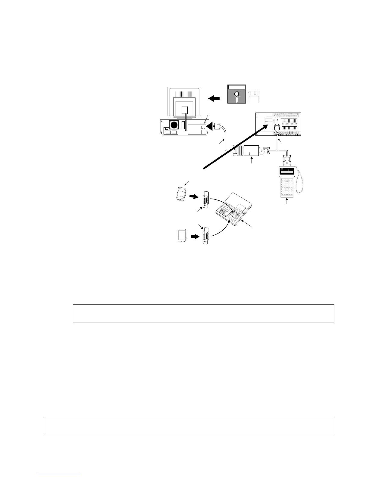
■ Writing a program to the memory (EPROM) via the master memory (EEPROM) with a
commercially available ROM programmer
[Program in FP1’s internal RAM → Master memory (EEPROM) → commercially available ROM programmer’s
internal memory → memory (EPROM)]
Procedure:
1 Attach master memory (EEPROM)
to FP1 Control Unit. Transfer to
master memory (EEPROM) using
FP Programmer in FP1’s internal
RAM.
Remove master memory
(EEPROM) from FP1, and attach
to commercially available ROM
programmer.
2 Transfer contents of that master
memory (EEPROM) to the internal
memory of the ROM programmer.
Replace the ROM programmer’s
master memory (EEPROM) with
the memory (EPROM).
3 Write the contents of the ROM
programmer’s internal memory to
the memory (EPROM).
Necessary tools
• Computer: Commercially available
personal computer (IBM PC-AT or
100% compatible machine)
Main memory: 550 KB or more free
EMS: 800 KB or more free
Hard disk space: 2 MB or more required
Operating System: MS-DOS Ver. 3.30 or later
Video mode (Display mode): EGA or VGA
• NPST-GR Software Ver. 3: AFP266538
Note:
• RS232C cable (3 m / 9.843 ft.): AFB85833/AFB85853
• RS422/232C Adapter: AFP8550
• FP1 Peripheral Cable:
0.5 m / 1.640 ft.: AFP15205
3 m / 9.843 ft.: AFP1523
• FP Programmer II: AFP1114
• Socket adapter for FP ROM Writer: AFP1810
• Master Memory (EEPROM): AFP1202 (for C24 and C40 series)
AFP1203 (for C56 and C72 series)
• Memory (EPROM): AFP1201
• Commercially available ROM programmer: We recommend Aval Data Corporation’s PECKER 11.
Note:
• When using NPST-GR Software Ver. 2, refer to page 241, “1. Differences Between NPST-GR Ver. 2.4
and 3.1.”
• The .EXE files are compressed in the system disks. When installing the NPST-GR, you will
have to expand them.
18
1-4. Programming Tools
RS232C interface
RS232C cable
Rear view
FP1 Peripheral Cable
NPST-GR Software
COM0COM1COM2COM3COM4COM5COM6COM
7
+-
24V DC
F.G.
COM
F89EABCD
(+)
-
COM
70162345
(+)
-
RUN
REMOTE
PROG.
V0
max.
min.
RUN
PROG.
ERR.
ALRAM
BATTERY
V1
max.
24V DC
+
-
min.
FP1 Control Unit
RS422/232C ADAPTER
AFP8536
National
MATUSITA ELECTRIC WORKS. LTD
MADE IN JAPAN
POWER
TXD(-)
RXD(-)
RS422
RS232C
RS422/232C Adapter
Commercially available
personal computer
(IBM PC-AT or 100% compatible)
F
P1
M
E
M
O
RY
U
N
IT
M
A
T
U
S
IT
A
E
L
E
C
T
R
IC
W
O
R
K
S
.
L
T
D
M
A
D
E
I
N
J
A
P
A
N
Socket adapter
for FP ROM Writer
Memory
(EPROM)
FP Programmer II
F
P
1
M
E
M
O
R
Y
U
N
IT
M
A
T
U
S
I
T
A
E
L
E
C
T
R
I
C
W
O
R
K
S
.
L
T
D
M
A
D
E
I
N
J
A
P
A
N
Commercially available
ROM programmer
Master Memory
(EEPROM)
F
P
1
M
E
M
O
R
Y
U
N
IT
M
A
T
U
S
I
T
A
E
L
E
C
T
R
I
C
W
O
R
K
S
.
L
T
D
M
A
D
E
I
N
J
A
P
A
N
FP PROGRAMMER
ST
X•WXANY•WYORR•WROTL•WL
FN/P
FL
NOT
DT/Ld
STK
IX/IY
TM
T•SV
CT
C•EV
(BIN)
K/H
=
CDD<E>F
SHIFT
SC
89AB
4 5 6 7
0 1 2 3
(-)
OP
SRC
READ
(HELP)
CLR
ACLR
(DELT)
INST
ENT
WRT

■ Writing a program to the memory (EPROM) with NPST-GR Software and a commercially
available ROM programmer
[Program with NPST-GR Software → Commercially available ROM programmer’s internal memory → memory
(EPROM)]
Procedure:
1 Transfer the program from the personal computer to
the commercially available ROM programmer’s
internal memory with NPST-GR Software.
2 Attach the memory (EPROM) to the ROM
programmer, and write the program.
Necessary tools
• Computer: Commercially available personal computer
(IBM PC-AT or 100% compatible machine)
System required:
- Main memory: 550 KB or more free
- EMS: 800 KB or more free
- Hard disk space: 2 MB or more
- Operating System: MS-DOS Ver. 3.30 or later
- Video mode (Display mode): EGA or VGA
• NPST-GR Software Ver. 3: AFP266538
Note:
• RS232C cable:
Select in accordance with the specifications of the
commercially available ROM programmer.
• Commercially available ROM programmer:
We recommend Aval Data Corporation’s PECKER 11.
• Socket adapter for FP ROM Writer: AFP1810
• Memory (EPROM): AFP1201
• The .EXE files are compressed in the
system disks. When installing the NPSTGR, you will have to expand them.
19
1-4. Programming Tools
RS232C interface
RS232C cable
Rear view
NPST-GR Software
Commercially available
personal computer
(IBM PC-AT or 100% compatible)
Socket adapter
for FP ROM Writer
Memory
(EPROM)
F
P
1
M
E
M
O
R
Y
U
N
I
T
MA
T
US
IT
A
E
LE
CTR
IC W
OR
KS
. LTD
MA
DE
IN JAP
AN
Commercially available
ROM programmer

20

CHAPTER 2
SPECIFICATIONS
2-1. Parts Terminology and Functions..........................................22
1. Control Unit......................................................................22
1) C14 and C16 Series ...............................................22
2) C24, C40, C56, and C72 Series.............................23
2. Expansion Unit .................................................................24
1) E8 and E16 Series .................................................24
2) E24 and E40 Series................................................24
3. Intelligent Unit..................................................................25
1) FP1 A/D Converter Unit........................................25
2) FP1 D/A Converter Unit........................................25
4. Link Unit ..........................................................................26
1) FP1 Transmitter Master Unit.................................26
2) FP1 I/O Link Unit..................................................27
3) C-NET Adapter S1 Type .......................................28
2-2. Specifications ........................................................................29
1. General Specifications......................................................29
2. Performance Specifications of Control Unit
and Expansion Unit ..........................................................31
1) Control Specifications ...........................................31
2) Input Specifications of Control Unit
and Expansion Unit................................................32
3) Output Specifications of Control Unit
and Expansion Unit................................................33
3. Performance Specifications of Intelligent Unit ................35
1) FP1 A/D Converter Unit........................................35
2) FP1 D/A Converter Unit........................................35
4. Performance Specifications of Link Unit.........................36
1) FP1 Transmitter Master Unit.................................36
2) FP1 I/O Link Unit..................................................36
3) C-NET Adapter S1 Type .......................................36
5. Dimensions.......................................................................37
1) Control Unit...........................................................37
2) Expansion Unit ......................................................37
3) Intelligent Unit.......................................................38
4) Link Unit................................................................38
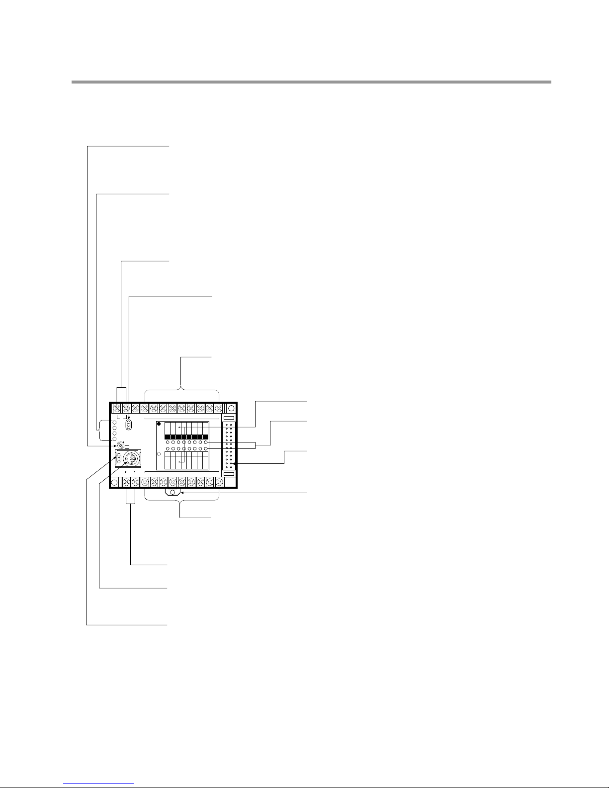
22
2-1. Parts Terminology and Functions
2-1. Parts Terminology and Functions
1. Control Unit
1) C14 and C16 Series (Illustration: C16 series, AC type)
01234567
01234567
COM01234567F.G.
100-240V
AC
RUN
PROG.
ERR.
ALARM
RUN
REMOTE
PROG.
COM
01234567
OUTPUT
INPUT
X Y
(Relay)(24V DC)
+
(+)
-
24V DC
V0
max.min.
FP1-001-93-B
2-1. Parts Terminology and Functions
Programming Tools Connector (RS422 port):
Use this connector to connect the programming tools (e.g., FP Programmer II or personal computer with
NPST-GR Software) using the FP1 Peripheral Cable.
Baud Rate Selector:
Selects the baud rate for communication with a peripheral device (FP Programmer, FP Programmer II or
personal computer with NPST-GR Software).
Sets the baud rate selector according to the peripheral device to be connected to the RS422 port.
FP Programmer (AFP1112): 19,200 bps
FP Programmer (AFP1112A): 19,200 bps or 9,600 bps
FP Programmer II (AFP1114): 19,200 bps or 9,600 bps
Personal computer with NPST-GR: 9,600 bps
Potentiometer (V0):
Set with a screwdriver, the potentiometer allows you to manually adjust the controller. This feature lets
you input an analog value ranging from 0 to 255. The set value is stored in the manual dial-set register
(DT9040).
Operation Monitor LEDs:
RUN LED ON: when program is executed
Flashes: when forcing input/output is executed in RUN mode
PROG. LED ON: when the Control Unit halts program execution
ERR. LED ON: when a self-diagnostic error occurs
ALARM LED ON: when an abnormality is detected or watchdog timer error occurs
Mode Selector:
RUN mode: The Control Unit executes programs.
REMOTE mode: The mode (RUN mode or PROG. mode) can be changed using programming
tools (e.g., FP Programmer II and personal computer with NPST-GR Software).
PROG. mode: You can edit a program.
Power Supply Terminals:
• AC type Control Unit: power supply terminals for 100 V AC to 240 V AC
• DC type Control Unit: power supply terminals for 24 V DC
Output Terminals:
C14 series: 6 points, C16 series: 8 points
I/O Name Board
I/O State Indicators:
Indicates the input and output ON/OFF states.
Expansion Connector:
Connects to the FP1 Expansion Unit or FP1 Intelligent Unit (FP1
A/D Converter Unit or FP1 D/A Converter Unit) or FP1 I/O Link Unit.
See page 12 and 42.
DIN Rail Attachment Lever
Input Terminals:
C14 and C16 series: 8 points
Input voltage range: 12 V DC to 24 V DC
Built-in DC Power Output Terminals for Inputs (AC type only):
DC power for inputs can be supplied from these terminals. See page 45.
 Loading...