

NAiS FP Technical Manual
Programmable Controller
FP0 RTD Unit
Technical Manual
is a global brand name of Matsushita Electric Works.

BEFORE BEGINNING
Liability and Copyright for the Hardware
This manual and everything described in it are copyrighted. You may not copy this manual, in
whole or part, without written consent of Matsushita Electric Works (Europe) AG.
Matsushita Electric Works (Europe) AG pursues a policy of continuous improvement of the
design and performance of its products, therefore, we reserve the right to change the
manual/product without notice. In no event will Matsushita Electric Works (Europe) AG be
liable for direct, special, incidental, or consequential damage resulting from any defect in the
product or its documentation, even if advised of the possibility of such damages.
We invite your comments on this manual. Please email us at:
tech-doc@euro.de.mew.com.
Please direct support matters and technical questions to your local Matsushita representative.
LIMITED WARRANTY
If physical defects caused by distribution are found, Matsushita Electric Works (Europe) AG
will replace/repair the product free of charge. Exceptions include:
• When physical defects are due to different usage/treatment of the product other than
described in the manual.
• When physical defects are due to defective equipment other than the distributed
product.
• When physical defects are due to modifications/repairs by someone other than
Matsushita Electric Works (Europe) AG.
• When physical defects are due to natural disasters.
©MS-DOS and Windows are registered trademarks of Microsoft Corporation.
©IBM Personal Computer AT is registered trademark of the International Business Machines Corporation.
Important Symbols
One or more of the following symbols may be used in this manual:
WARNING
!
The warning triangle indicates especially important safety instructions. If they are not
adhered to, the results could be:
• fatal or critical injury and/or
• significant damage to instruments or their contents, e.g. data
NOTE
Contains important additional information.
EXAMPLE
Contains an illustrative example of the previous text section.
PROCEDURE
Indicates that a step-by-step procedure follows.
REFERENCE
Indicates where you can find additional information on the subject at hand.
ii

CAUTION
Indicates that you should proceed with caution.
KEY POINTS
Summarizes key points in a concise manner.
SHORTCUTS
Provides helpful keyboard shortcuts.
EXPLANATION
Provides brief explanation of a function, e.g. why or when you should use it.
iii


Table of Contents
FP0 RTD Unit
Table of Contents
BEFORE BEGINNING ......................................................................................i
LIMITED WARRANTY ......................................................................................i
Important Symbols .........................................................................................ii
Precautions Before Use ...............................................................................vii
1 Unit Outline.............................................................................................1
1.1 Functions ................................................................................................................ 1
1.2 Product Number .....................................................................................................1
1.3 Expansion Limit ...................................................................................................... 1
1.4 Part Names and Functions..................................................................................... 2
2 Input Range Setting Switch...................................................................4
3 Wiring......................................................................................................5
4 Conversion Characteristics ..................................................................6
4.1 Pt100 ......................................................................................................................6
4.2 Pt1000 .................................................................................................................... 8
4.3 Ni1000 .................................................................................................................. 10
4.4 Resistor ................................................................................................................12
5 I/O Allocation and Sample Programs ................................................. 14
5.1 I/O Numbers ......................................................................................................... 14
5.2 Programming with FPWIN Pro ............................................................................. 16
5.3 Programming with FPWIN GR .............................................................................17
5.3.1 RTD Types Pt100, Pt1000, Ni1000.......................................................... 17
5.3.2 RTD Type Resistor................................................................................... 18
v

Table of Contents
FP0 RTD Unit
6 When an Error Occurs.........................................................................20
6.1 Troubleshooting.................................................................................................... 20
6.2 Digital Value When Out Of Measuring Range...................................................... 20
7 Specifications.......................................................................................21
8 Dimensions...........................................................................................24
Index ..............................................................................................................25
Record of Changes.......................................................................................27
vi

Precautions Before Use
FP0 RTD Unitnit
Precautions Before Use
Accuracy
When extremely sensitive temperature data is required, use the temperature data obtained 15
minutes after turning ON the FP0 RTD unit. (The temperature data obtained in the first 15
minutes is, however, within the total accuracy range.)
A rapid temperature change in the FP0 RTD unit might change the temperature data
temporarily.
A draft (air) created e.g. by a cooling fan built into the control panel and blowing on the FP0
RTD unit will lower accuracy. Avoid any kind of draft.
Programming
Between power ON and the first valid conversion data, the digital value will be 8191 or 16383.
When programming, be sure not to use the data obtained during this period.
When the RTD is broken, the digital value will change to 8191 or 16383. When programming
avoid any risks resulting from a broken RTD. A broken RTD needs to be replaced.
vii


FP0 RTD Unit
Unit Outline
1 Unit Outline
1.1 Functions
RTD input unit for the FP0/FPΣ control unit.
The temperature data obtained using the RTD (Resistance Temperature Detector) is
converted to the digital value to be read into the FP0/ FPΣ control unit.
Available RTD types
Pt100 (to IEC751), Pt1000 (to IEC751), Ni1000 (to DIN43760), and Resistor.
Temperature measurement ranges available
RTD
Type
Pt100 -200.0 … +500.0 -80.00 … +80.00 -328.0 … +800.0 -80.00 … +80.00
Pt1000 -200.0 … +300.0 -80.00 … +80.00 -328.0 … +572.0 -80.00 … +80.00
Ni1000 -30.0 … +150.0 -30.00 … +80.00 -22.0 … +302.0 -22.00 … +80.00
Resolution 0.1K Resolution 0.01K Resolution 0.1°F Resolution 0.01°F
°C °F
Resistor measurement ranges available
RTD
Type
Resistor 20 … +2200 20.0 … 1630.0
Resolution 1 Ω Resolution 0.1 Ω
Ω
Conversion to degrees Celsius or degrees Fahrenheit possible
The temperature data measured using the sensor is converted to degrees Celsius or degrees
Fahrenheit inside the FP0 RTD unit.
Broken-RTD detector attached
A broken RTD can be detected.
1.2 Product Number
Product name RTD input points Product number Part number
FP0 RTD unit 6 points FP0RTD6 AFP0430
1.3 Expansion Limit
Number
Up to 3 expansion units can be connected to the control unit.
Position
Always install the FP0 RTD unit the farthest to the right of the control unit.
1
Unit Outline
FP0 RTD Unit
REFERENCE
For further information, see page 14, I/O Allocation and Sample Programs.
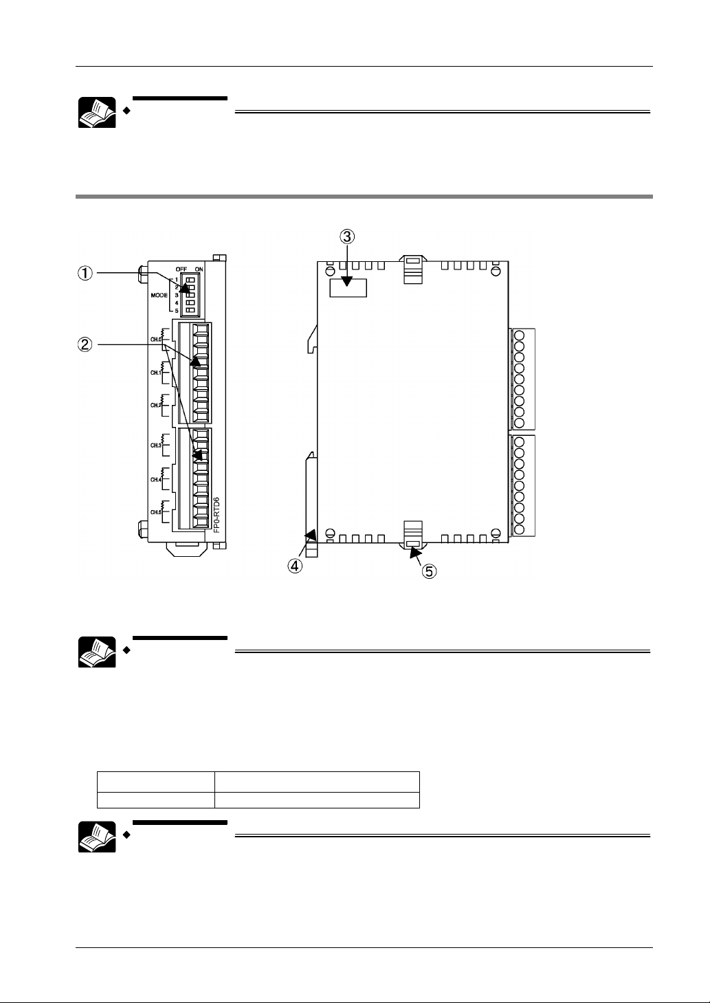
1.4 Part Names and Functions
Left sideFront
1. Input range setting switch
DIP switches to change between the input ranges (RTD types).
REFERENCE
For further information, see page 4, Input Range Setting Switch
2. RTD input terminal block (9-pin)
Manufactured by Phoenix Contact Co. Model No: MC1.5/9-ST-3.5 (Product No.: 1840434).
Suitable wires
Size Nominal cross-sectional area
AWG# 28 to 16 0.08 mm2 to 1.25mm
REFERENCE
FP0 Hardware Manual “Wiring the Terminal Type”
FP∑ User’s Manual “Wiring of Terminal Block Type”
2
2

FP0 RTD Unit
3. Expansion connector
Connects the expansion unit to the internal circuit of the control unit.
Unit Outline
REFERENCE
FP0 Hardware Manual: “Expansion I/O Units”
FP∑User’s Manual: “Expansion”
4. DIN rail attachment lever (one-touch hook)
The unit can be installed to the DIN rail by one-touch operation. The one-touch hook is also
used for installing the unit to the FP0 Slim Type Mounting Plate (AFP0803).
5. Expansion hook
Used to secure expansion units.
3
 Loading...