

NAIS DS4E-SL2-DC9V, DS4E-SL2-DC6V, DS4E-SL2-DC5V, DS4E-SL2-DC48V, DS4E-SL2-DC3V Datasheet
...
186
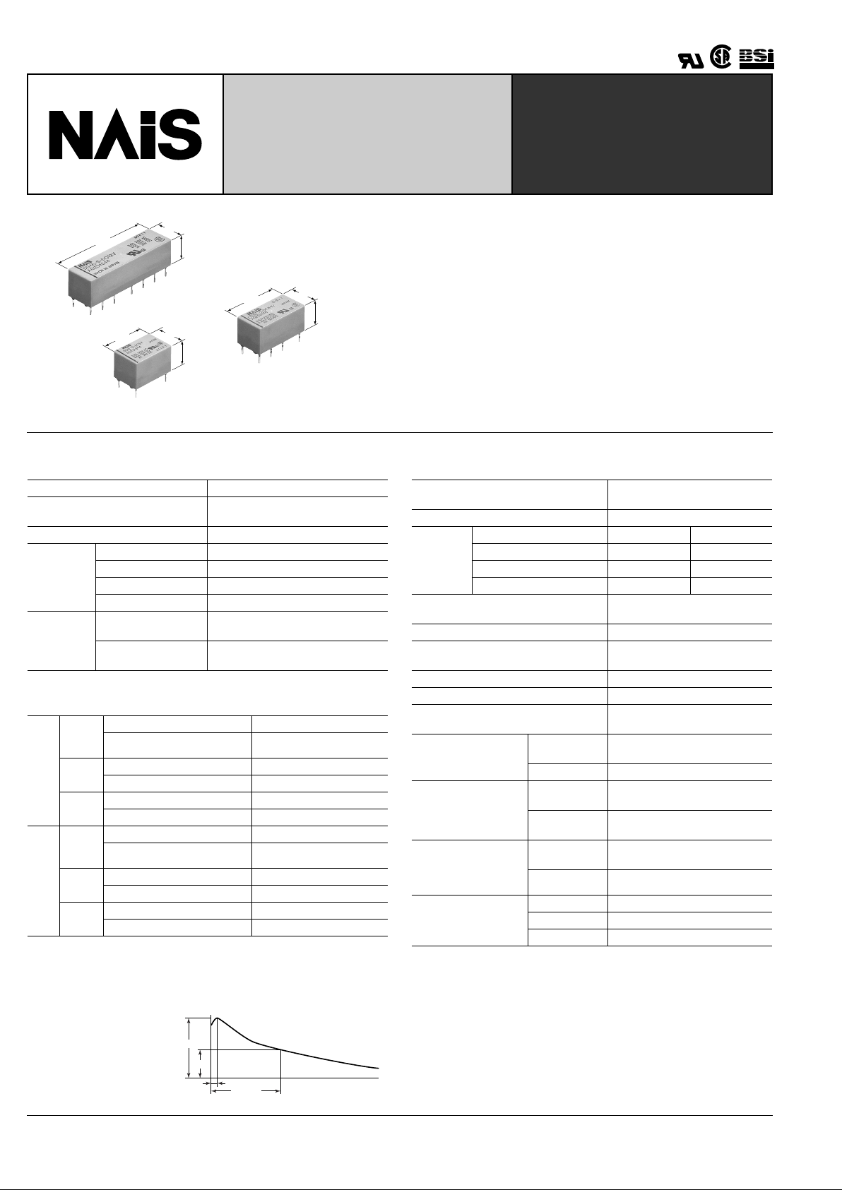
DS-RELAYS
HIGHLY SENSITIVE 1500 V
FCC SURGE WITHST ANDING
MINIATURE RELAY
TESTING
DS4E
35.24
1.387
9.9
.390
9.8
.386
DS1E
15
.590
9.9
.390
9.8
.386
DS2E
20
.787
9.9
.390
9.8
.386
FEATURES
• High sensitivity: 200 mW pick-up power
100 mW pick-up power types available
• Latching types available
• High switching capacity: 60 W, 125 V A
• High breakdown voltage: 1,500 V FCC surge between open contacts
1,000 V AC between open contacts
• DIP-1C type can be used with 14 pin IC socket
2C type can be used with 16 pin IC socket,
4C type can be used with 2 sets of 14 pin IC sockets
• Gold-cap silver palladium types available for 2 Form C type
• Bifurcated contacts are standard
SPECIFICATIONS
Contact
* Gold capped silver-palladium contact also available f or 2 F orm C 10
7
operations at
0.1 A 50 V DC resistive
Coil (polarized) (at 20 ° C 68 ° F)
* For 1 Form C high sensitive types.
Characteristics (at 20 ° C 68 ° F)
Arrangement 1 Form C, 2 Form C, 4 Form C
Initial contact resistance, max.
(By voltage drop 6 V DC 1 A)
50 m Ω
Contact material Gold-clad sliver
Rating
(resistive)
Max. switching power
60 W, 125 VA
Max. switching voltage
220 V DC, 250 V AC
Max. switching current
2 A DC, AC
Max. carrying current
3 A DC, AC
Expected
life (min.
operations)
Mechanical
(at 600 cpm)
10
8
(1 Form C 2 coil latching type: 10
7
)
Electrical
2 A 30 VDC resistive
5 × 10
5
M
type
Single
side
stable
Minimum operating power
Approx. 200 mW
Nominal operating power
Approx. 400 mW
1 coil
latching
Minimum set and reset power
Approx. 90 mW
Nominal set and reset power
Approx. 180 mW
2 coil
latching
Minimum set and reset power
Approx. 180 mW
Nominal set and reset power
Approx. 360 mW
S
type
Single
side
stable
Minimum operating power
Approx. 100 mW (128 mW)*
Nominal operating power
Approx. 200 mW
1 coil
latching
Minimum set and reset power
Approx. 45 mW (58 mW)*
Nominal set and reset power
Approx. 90 mW
2 coil
latching
Minimum set and reset power
Approx. 90 mW (115 mW)*
Nominal set and reset power
Approx. 180 mW
Max. operating speed
20 cpm at rated load
50 cps at low level load
Initial insuration resistance*
1
Min. 100 M Ω (at 500 V DC)
Initial
breakdown voltage*
2
Type of relay (DS1-S type) (Other types)
Between open contacts 500 Vrms 1,000 Vrms
Between contacts sets — 1,000 Vrms
Between contacts and coil
1,000 Vrms 1,500 Vrms
FCC surge voltage between contacts
and coil
1,500 V (Expect DS1-S type)
Operate time*
3
(at nominal voltage) Approx. 3 ms
Release time (without diode)*
3
(at
nominal voltage)
Approx. 2 ms
Set time*
3
(at nominal voltage) Approx. 3 ms
Reset time*
3
(at nominal voltage) Approx. 3 ms
Temperature rise
(at nominal voltage, Contact current: 2A)
Max. 65 ° C
Shock resistance
Functional*
4
1C, 2C:Min. 490 m/s
2
{50 G}
4C:Min. 294 m/s
2
{30 G}
Destructive*
5
Min. 980 m/s
2
{100 G}
Vibration resistance
Functional*
6
10 to 55 Hz
at double amplitude of 3.3 mm
Destructive
10 to 55 Hz
at double amplitude of 5 mm
Conditions for operation,
transport and storage*
7
(Not freezing and condensing at low temperature)
Ambient
temp.
–40 ° C to +70 ° C
–40 ° F to +158 ° F
Humidity 5 to 85% R.H.
Unit weight
1 Form C Approx. 3.2g .11oz
2 Form C Approx. 4g .14oz
4 Form C Approx. 7g .25oz
FCC (Federal Communication Commission) requests following standard as Breakdown Voltage
specification.
10 µs
1500V
750V
160 µs
Remarks
* Specifications will vary with foreign standards certification ratings.
*
1
Measurement at same location as "Initial breakdown voltage" section
*
2
Detection current: 10 mA
*
3
Excluding contact bounce time
*
4
Half-wave pulse of sine wave: 11ms; detection time: 10 µ s
*
5
Half-wave pulse of sine wave: 6ms
*
6
Detection time: 10 µ s
*
7
Refer to 5. Conditions for operation, transport and storage mentioned in
AMBIENT ENVIRONMENT (Page 61)
mm inch

DS
187
TYPICAL APPLICATIONS
• T elecomm unication equipment
• Office equipment
• Computer peripherals
• Security equipment
• Measuring instrumentation
ORDERING INFORMATION
Contact
arrangement
2Ex DS
1: 1 Form C
2: 2 Form C
4: 4 Form C
*Reverse polarity types available (add suffix-R). Standard packing: Carton: 50 pcs.; Case: 500 pcs.
E M R
*
L2 DC 48 V
Coil voltage
DC 1.5, 3,
5, 6, 9, 12,
24, 48 V
Classification
of type
E: Amber
sealed type
Sensitivity
M: 400 mW nominal
operating power
S: 200 mW nominal
operating power
Operating function
Nil: Single side stable
L: 1 coil latching
L2: 2 coil latching
TYPES
Single side stable
1 coil latching
2 coil latching
Notes:
1. Reverse polarity types available (add suffix-R).
2. Standard packing: carton: 50 pcs.; case: 500 pcs.
Nominal Voltage , V DC
Part No.
1 Form C 2 Form C 4 Form C
M
(400 mW)
type
1.5 DS1E-M-DC1.5V DS2E-M-DC1.5V DS4E-M-DC1.5V
3 DS1E-M-DC3V DS2E-M-DC3V DS4E-M-DC3V
5 DS1E-M-DC5V DS2E-M-DC5V DS4E-M-DC5V
6 DS1E-M-DC6V DS2E-M-DC6V DS4E-M-DC6V
9 DS1E-M-DC9V DS2E-M-DC9V DS4E-M-DC9V
12 DS1E-M-DC12V DS2E-M-DC12V DS4E-M-DC12V
24 DS1E-M-DC24V DS2E-M-DC24V DS4E-M-DC24V
48 DS1E-M-DC48V DS2E-M-DC48V DS4E-M-DC48V
S
(200 mW)
type
1.5 DS1E-S-DC1.5V DS2E-S-DC1.5V DS4E-S-DC1.5V
3 DS1E-S-DC3V DS2E-S-DC3V DS4E-S-DC3V
5 DS1E-S-DC5V DS2E-S-DC5V DS4E-S-DC5V
6 DS1E-S-DC6V DS2E-S-DC6V DS4E-S-DC6V
9 DS1E-S-DC9V DS2E-S-DC9V DS4E-S-DC9V
12 DS1E-S-DC12V DS2E-S-DC12V DS4E-S-DC12V
24 DS1E-S-DC24V DS2E-S-DC24V DS4E-S-DC24V
48 DS1E-S-DC48V DS2E-S-DC48V DS4E-S-DC48V
Nominal Voltage , V DC
Part No.
1 Form C 2 Form C 4 Form C
M
(180 mW)
type
1.5 DS1E-ML-DC1.5V DS2E-ML-DC1.5V DS4E-ML-DC1.5V
3 DS1E-ML-DC3V DS2E-ML-DC3V DS4E-ML-DC3V
5 DS1E-ML-DC5V DS2E-ML-DC5V DS4E-ML-DC5V
6 DS1E-ML-DC6V DS2E-ML-DC6V DS4E-ML-DC6V
9 DS1E-ML-DC9V DS2E-ML-DC9V DS4E-ML-DC9V
12 DS1E-ML-DC12V DS2E-ML-DC12V DS4E-ML-DC12V
24 DS1E-ML-DC24V DS2E-ML-DC24V DS4E-ML-DC24V
48 DS1E-ML-DC48V DS2E-ML-DC48V DS4E-ML-DC48V
S
(90 mW)
type
1.5 DS1E-SL-DC1.5V DS2E-SL-DC1.5V DS4E-SL-DC1.5V
3 DS1E-SL-DC3V DS2E-SL-DC3V DS4E-SL-DC3V
5 DS1E-SL-DC5V DS2E-SL-DC5V DS4E-SL-DC5V
6 DS1E-SL-DC6V DS2E-SL-DC6V DS4E-SL-DC6V
9 DS1E-SL-DC9V DS2E-SL-DC9V DS4E-SL-DC9V
12 DS1E-SL-DC12V DS2E-SL-DC12V DS4E-SL-DC12V
24 DS1E-SL-DC24V DS2E-SL-DC24V DS4E-SL-DC24V
48 DS1E-SL-DC48V DS2E-SL-DC48V DS4E-SL-DC48V
Nominal Voltage , V DC
Part No.
1 Form C 2 Form C 4 Form C
M
(360 mW)
type
1.5 DS1E-ML2-DC1.5V DS2E-ML2-DC1.5V DS4E-ML2-DC1.5V
3 DS1E-ML2-DC3V DS2E-ML2-DC3V DS4E-ML2-DC3V
5 DS1E-ML2-DC5V DS2E-ML2-DC5V DS4E-ML2-DC5V
6 DS1E-ML2-DC6V DS2E-ML2-DC6V DS4E-ML2-DC6V
9 DS1E-ML2-DC9V DS2E-ML2-DC9V DS4E-ML2-DC9V
12 DS1E-ML2-DC12V DS2E-ML2-DC12V DS4E-ML2-DC12V
24 DS1E-ML2-DC24V DS2E-ML2-DC24V DS4E-ML2-DC24V
48 DS1E-ML2-DC48V DS2E-ML2-DC48V DS4E-ML2-DC48V
S
(180 mW)
type
1.5 DS1E-SL2-DC1.5V DS2E-SL2-DC1.5V DS4E-SL2-DC1.5V
3 DS1E-SL2-DC3V DS2E-SL2-DC3V DS4E-SL2-DC3V
5 DS1E-SL2-DC5V DS2E-SL2-DC5V DS4E-SL2-DC5V
6 DS1E-SL2-DC6V DS2E-SL2-DC6V DS4E-SL2-DC6V
9 DS1E-SL2-DC9V DS2E-SL2-DC9V DS4E-SL2-DC9V
12 DS1E-SL2-DC12V DS2E-SL2-DC12V DS4E-SL2-DC12V
24 DS1E-SL2-DC24V DS2E-SL2-DC24V DS4E-SL2-DC24V
48 DS1E-SL2-DC48V DS2E-SL2-DC48V DS4E-SL2-DC48V
 Loading...