

NAIS CF2-12V Datasheet
CF
367
CF-RELAYS
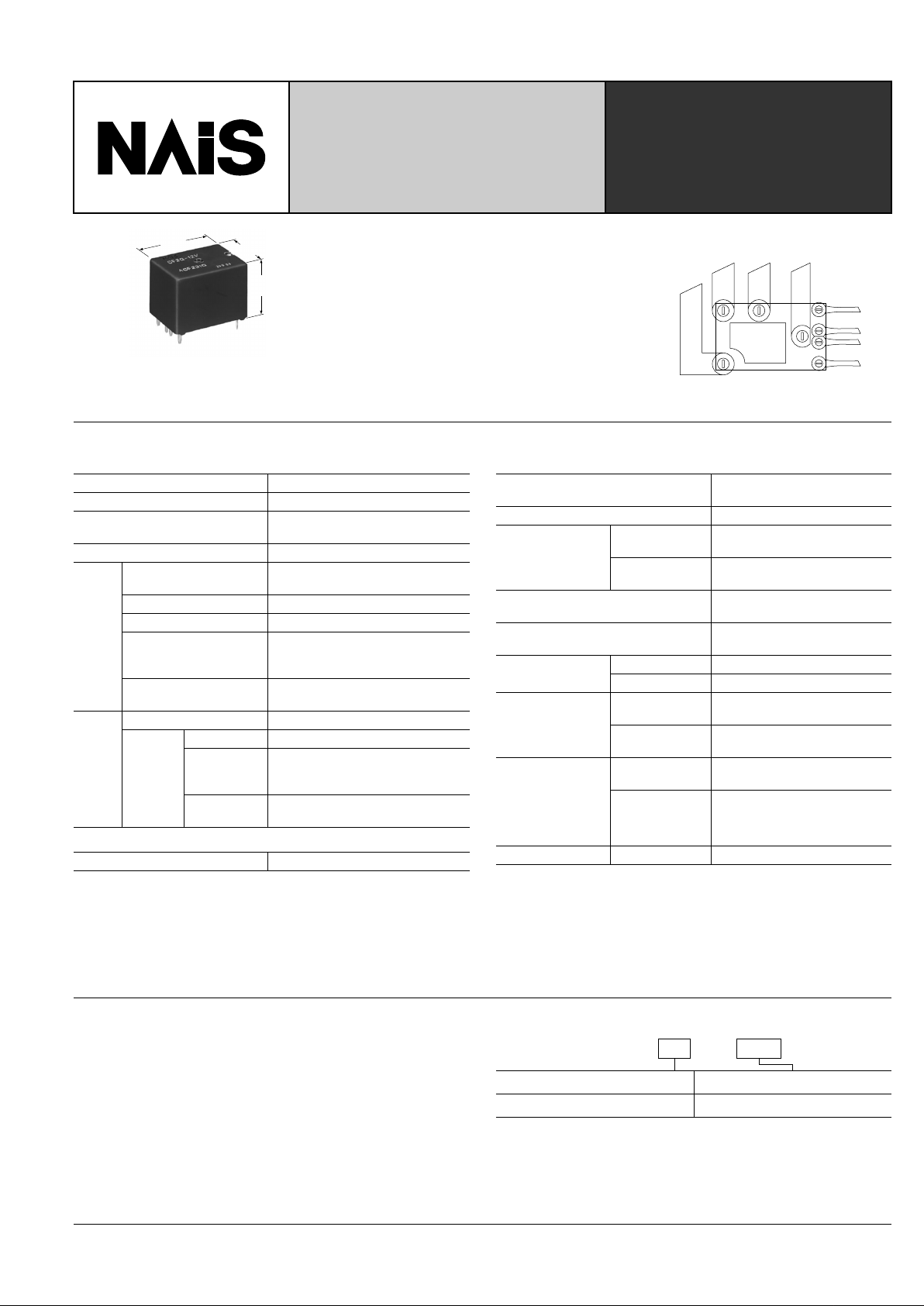
NEW DUAL POWER
AUTOMOTIVE RELAY
mm inch
16.5
.650
16.5
.650
22.5
.886
FEATURES
• 7 Amp Steady/30 Amp Inrush current
capability
• Simple footprint enables ease of PC
board layout
Normally
Open
Open
Space
Common
Normally
Closed
Coil 1
Coil 2
SPECIFICATIONS
Contact
Coil
Characteristics
Arrangement 1 Form C × 2 (H bridge)
Contact material Silver alloy
Initial contact resistance, max.
(By voltage drop 6 V DC 1 A)
50 m Ω
Contact voltage drop, max. 0.2 V (at 20 A switching)
Rating
Nominal switching
capacity
N.O.: 20A 14 V DC
N.C.: 10A 14 V DC
Max. switching power 140 W
Max. switching voltage 16 V DC
Max. make current
10 A (Continuous),
30 A (within 1 min.; coil applied
voltage: 12 V, at 20 ° C)
Max. carrying current
30 A (2 minutes ), 20A (1 hour)
(coil applied voltage: 12 V, at 20 ° C)
Expect
ed life
(min.
ope.)
Mechanical (at 180 cpm) 10
6
Electrical
resistive load Min.10
5
7 A 14 V DC,
Inrush 30 A
(Motor load)
2 × 10
5
20 A 14 V DC
(Motor lock)
Min.5 × 10
4
Nominal operating power 640 mW
Max. operating speed
(at rated load)
6 cpm
Initial insulation resistance*
1
Min. 100 m Ω (at 500 V DC)
Initial breakdown
voltage*
2
Between open
contacts
1,000 Vrms for 1 min.
Between
contacts and coil
1,000 Vrms for 1 min.
Operate time*
3
(at nominal voltage)
Max. 10 ms
Release time (without diode)*
3
(at nominal voltage)
Max. 10 ms
Shock resistance
Functional*
4
Min. 100 m/s
2
{10 G}
Destructive*
5
Min. 1,000 m/s
2
{100 G}
Vibration
resistance
Functional*
6
Approx. 44.1 m/s2 {4.5 G},
10 to 100 Hz
Destructive
Approx. 44.1 m/s
2
{4.5 G},
10 to 500 Hz
Conditions for
operation, transport and storage*
7
(Not freezing and
condensing at low
temperature)
Ambient temp.
–40 ° C to + 85 ° C
–40 ° F to +185 ° F
Humidity 5 to 85%R.H.
Unit weight Standard type Approx. 15 g .529 oz
Remarks
* Specifications will vary with foreigh standards certification ratings.
*
1
Measurement at same location as "Intial breakdown voltage" section
*
2
Detection current: 10mA
*
3
Excluding contact bounce time
*
4
Half-wave pulse of sine wave: 11ms; detection time: 10 µ s
*
5
Half-wave pulse of sine wave: 6ms
*
6
Detection time: 10 µ s
*
7
Refer to 5. Conditions for operation, transport and storage mentioned in
AMBIENT ENVIRONMENT (Page 61)
TYPICAL APPLICATIONS
• Automotive: Power-window, power sunroof, etc.
ORDERING INFORMATION
Contact arrangement Coil voltage(DC)
1 Form C × 2
Standard packing: Carton: 35pcs.; Case: 700pcs.
12 V
Ex. CF 2 12 V–
CF
368
TYPES AND COIL DATA (at 20 ° C 68 ° F)
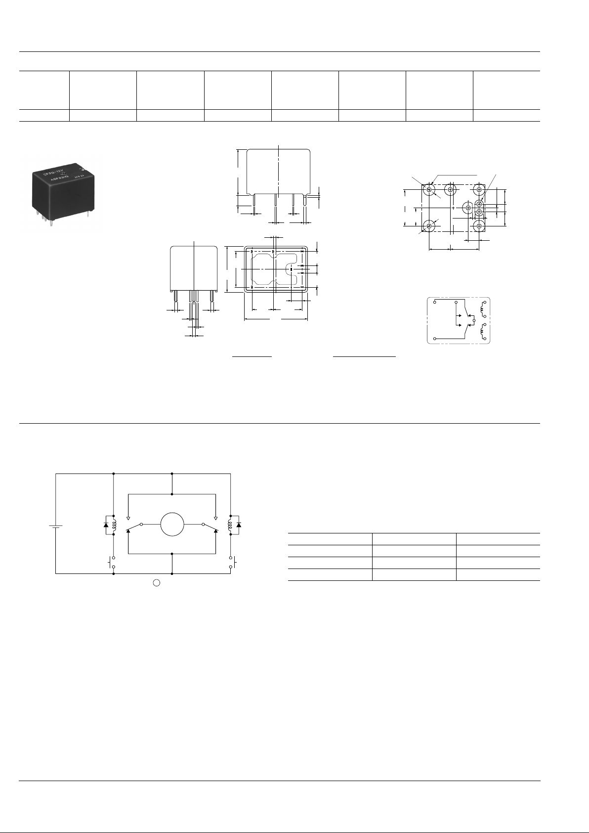
DIMENSIONS
Part No.
Nominal voltage,
V DC
Pick-up voltage,
V DC (max.)
Drop-out
voltage,
V DC (min.)
Coil resistance,
Ω ( ±
10%)
Nominal
operating
current,
mA ( ± 10%)
Nominal
operating Pow er ,
mW
Usable voltage
range,
VDC
CF2-12V 12 7.2 1.0 225 53.3 640 10 to 16
mm inch
0.3
.012
0.3
.012
0.3
.012
1.1
.043
1
.039
3.5
.138
16.5
.650
1.2 max.
.047 max.
5.08
.200
5.08
.200
12.7
.500
16.5
.650
1.1
.043
1.1
.043
1.1
.043
0.4
.016
0.4
.016
7.62
.300
22.5
.886
10.16
.400
3.81
.150
2.54
.100
Recommended PC board pattern
Schematic
7.62±0.1
.300±.004
(0.8)
(.031)
(3)
(.118)
(6-4 dia.)
(6-.157 dia.)
(R1.5)
Land diameter
10.16±0.1
.400±.004
6.35±0.1
.250±.004
12.7±0.1
.500±.004
8-1.5 dia.±0.1
8-.059 dia.±.004
5.08±0.1
.200±.004
1.27±0.1
.050±.004
2.54±0.1
.100±.004
5.08±0.1
.200±.004
3.81±0.1
.150±.004
N.C.
N.O.
COM1
COM2
EXAMPLE OF CIRCUITS
Forward/reverse control circuits of DC motor for power window
: Power window motor
12 V DC
SW A
M
M
SW B
N.O.
N.O.
N.C.
N.C.
COM COM
SW A SW B Motor
OFF OFF Stop
ON OFF Forward
OFF ON Reverse
Dimension: General tolerance
Max. 1mm .039 inch:
±
0.1 ± .004
1 to 3mm .039 to .118 inch: ± 0.2 ± .008
Min. 3mm .118 inch:
±
0.3 ± .012
 Loading...