

NAIS ASX220A4HX, ASX220A4H, ASX220A24Z, ASX220A24X, ASX220A24 Datasheet
...
SX
120
SX-RELAYS
HIGH SENSITIVITY RELA Y
WITH GUARANTEED LOW
LEVEL SWITCHING
CAPACITY
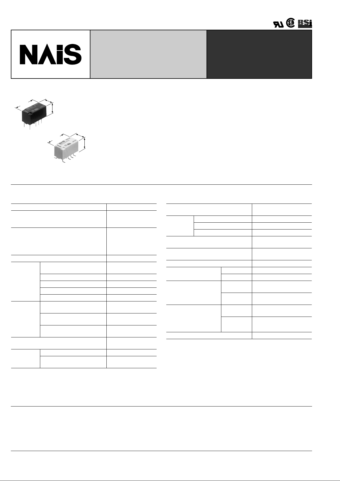
7.4
.291
15.0
.591
8.2
.323
mm inch
7.4
.291
15.0
.591
Max. 10.0
.394
FEATURES
1. High contact reliability over a long
life has been made possible for low
level loads.
Using a low level load (1 mV 10 µ A to 10 V
10 mA) 10
7
operations were achiev ed with
a static contact resistance of Max. 100
m Ω (voltage drop of 20 mV, 1 mA, 1 kHz)
and a dynamic contact resistance of Max.
1 Ω (Measurement delay 10 ms, voltage
drop of 20 mV, 1 mA, 1 kHz).
2. High sensitibity of 50 mW
By using the highly efficient polar magnetic circuit "seesaw balance armature
mechanism", a rated power consumption
of 50 mW (for single side stable type) has
been achieved.
3. Low thermal electromotive force
Reducing the heat from the coil enables a
thermal electromotive force of 3 µ V or
less.
SPECIFICATIONS
Contact
Notes:
**
1
This value can change due to the switching frequency , environmental conditions ,
and desired reliability level, therefore it is recommended to chec k this with the actual load.
**
2
For single side stable only.
Characteristics
Remarks:
* Specifications will vary with foreign standards certification ratings.
*
1
By nominal switching capacity: No. of operations: 10
7
*
2
Measurement at same location as "Initial breakdown voltage" section.
*
3
Detection current: 10mA.
*
4
Nominal voltage applied to the coil, excluding contact bounce time.
*
5
By resistive method, nominal voltage applied to the coil; contact carrying current:
10mA.
*
6
Half-wave pulse of sine wave: 6 ms; detection time: 10 µ s.
*
7
Half-wave pulse of sine wave: 6 ms.
*
8
Detection time: 10 µ s.
*
9
Refer to 5. Conditions for operation, transpor t and storage mentioned in
AMBIENT ENVIRONMENT (Page 61)
Arrangement 2 Form C
Static contact resistance (During initial and
electric life tests)*
1
(By voltage drop of 20 mV 1 mA [1kHz])
Max. 100 m Ω
Dynamic contact resistance (During initial and
electric life tests)*
1
(By voltage drop of 20 mV 1 mA[1 kHz], Measurement delay 10 ms after applying nominal
coil voltage)
Max. 1 Ω
Contact material Gold-clad silver alloy
Rating
Nominal switching capacity
(resistive load)
10 mA 10 VDC
Max. switching power 0.1 W
Max. switching voltage 10 VDC
Max. switching current 10 mA DC
Min. switching capacity**
1
10 µ A 1 mVDC
Nominal
operating
power
Single side stable
50mW (1.5 to 12 V DC)
70mW (24 V DC)
1 coil latching
35mW (1.5 to 12 V DC)
50mW (24 V DC)
2 coil latching
70mW (1.5 to 12 V DC)
150mW (24 V DC)
Thermal electromotive force, max.
(at nominal voltage applied to the coil**
2
)
3 µ V
Expected
life (min.
operations)
Mechanical (at 750 cpm) 5 × 10
7
Electrical (at 750 cpm)
(10 mA 10 V DC resistive load)
10
7
Initial insulation resistance*
2
Min. 10,000M Ω
(at 500V DC)
Initial
breakdown
voltage*
3
Between open contacts 750 Vrms for 1min.
Between contact sets 1,000 Vrms for 1min.
Between contact and coil 1,800 Vrms for 1min.
Operate time [Set time]*
4
(at 20 ° C)
Max. 5 ms (Approx. 3 ms)
[Max. 5 ms (Approx. 3 ms)]
Release time (without diode)
[Reset time]*
4
(at 20 ° C)
Max. 5 ms (Appro x. 1.5 ms)
[Max. 5 ms (Approx. 3 ms)]
Temperature rise*
5
(at 20 ° C) Max. 50 ° C
Shock resistance
Functional*
6
Min. 750 m/s
2
{75G]
Destructive*
7
Min. 1,000 m/s
2
{100G]
Vibration resistance
Functional*
8
10 to 55 Hz at double
amplitude of 3.3 mm
Destructive
10 to 55 Hz at double
amplitude of 5 mm
Conditions for operation,
transport and storage*
9
(Not freezing and condensing at low temperature)
Ambient
temperature
–40 ° C to 70 ° C
–40 ° F to 158 ° F
Humidity 5 to 85% R.H.
Unit weight Approx. 2 g .071 oz
TYPICAL APPLICATIONS
This relay will be used for the small load
for measuring instruments or others
where a stable contact resistance is
required.
TESTING
SX
121
ORDERING INFORMATION
200A Z1HEx. ASX
Contact arrangement
Terminal shapeOperating function Packing style
Coil voltage (DC)
Nil: Standard PC board terminal
A: Surface-mount terminal
2: 2 Form C 0: Single side stable
1: 1 coil latching
2: 2 coil latching
Type of operation
0: Standard type
(B.B.M.)
Nil: Tube packing
Z:
Tape and reel packing
(piked from 8/9/10/12
pin side)
1H: 1.5V
03 : 3V
4H: 4.5V
06 : 6V
09 : 9V
12 : 12V
24 : 24V
Note: Tape and reel packing symbol “-Z” is not marked on the relay. “X” type tape and reel packing (picked from 1/3/4/5-pin side) is also available. Suffix “X” instead of “Z”.
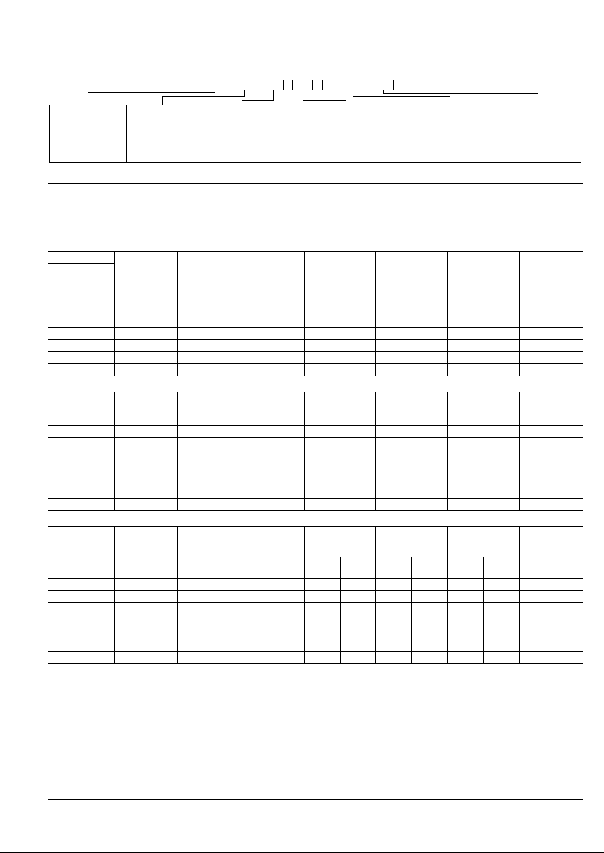
TYPES AND COIL DATA (at 20 ° C 68 ° F)
(1) Standard PC board terminal
1) Standard packing: 40 pcs. in an inner package (tube); 1,000 pcs. in an outer package
2) Specified value of pick-up, drop-out, set and reset voltage is with the condition of square wave coil pulse.
Single side stable
1 coil latching
2 coil latching
Part No.
Coil Rating,
V DC
Pick-up voltage,
V DC (max.)
(initial)
Drop-out
voltage,
V DC (min.)
(initial)
Nominal
operating current,
mA ( ± 10%)
Coil resistance,
Ω ( ±
10%)
Nominal
operating power,
mW
Max. allowable
voltage,
V DC
Standard PC
board terminal
ASX2001H 1.5 1.2 0.15 33.3 45 50 2.25
ASX20003 3 2.4 0.3 16.7 180 50 4.5
ASX2004H 4.5 3.6 0.45 11.1 405 50 6.75
ASX20006 6 4.8 0.6 8.3 720 50 9
ASX20009 9 7.2 0.9 5.6 1,620 50 13.5
ASX20012 12 9.6 1.2 4.2 2,880 50 18
ASX20024 24 19.2 2.4 2.9 8,229 70 36
Part No.
Coil Rating,
V DC
Set voltage,
V DC (max.)
(initial)
Reset voltage,
V DC (max.)
(initial)
Nominal
operating current,
mA ( ± 10%)
Coil resistance,
Ω ( ±
10%)
Nominal
operating power,
mW
Max. allowable
voltage,
V DC
Standard PC
board terminal
ASX2101H 1.5 1.2 1.2 23.3 64.3 35 2.25
ASX21003 3 2.4 2.4 11.7 257 35 4.5
ASX2104H 4.5 3.6 3.6 7.8 579 35 6.75
ASX21006 6 4.8 4.8 5.8 1,029 35 9
ASX21009 9 7.2 7.2 3.9 2,314 35 13.5
ASX21012 12 9.6 9.6 2.9 4,114 35 18
ASX21024 24 19.2 19.2 2.1 11,520 50 36
Part No.
Coil Rating,
V DC
Set voltage,
V DC (max.)
(initial)
Reset voltage,
V DC (max.)
(initial)
Nominal
operating current,
mA ( ± 10%)
Coil resistance,
Ω ( ±
10%)
Nominal
operating power,
mW
Max. allowable
voltage, V DC
Standard PC
board terminal
Set coil
Reset
coil
Set coil
Reset
coil
Set coil
Reset
coil
ASX2201H 1.5 1.2 1.2 46.7 46.7 32.1 32.1 70 70 2.25
ASX22003 3 2.4 2.4 23.3 23.3 129 129 70 70 4.5
ASX2204H 4.5 3.6 3.6 15.6 15.6 289 289 70 70 6.75
ASX22006 6 4.8 4.8 11.7 11.7 514 514 70 70 9
ASX22009 9 7.2 7.2 7.8 7.8 1,157 1,157 70 70 13.5
ASX22012 12 9.6 9.6 5.8 5.8 2,057 2,057 70 70 18
ASX22024 24 19.2 19.2 6.3 6.3 3,840 3,840 150 150 36
 Loading...