

NAIS ARZ225C12, ARZ225C05, ARZ220M24, ARZ220M12, ARZ220M05 Datasheet
...
RZ(ARZ1,2)
1
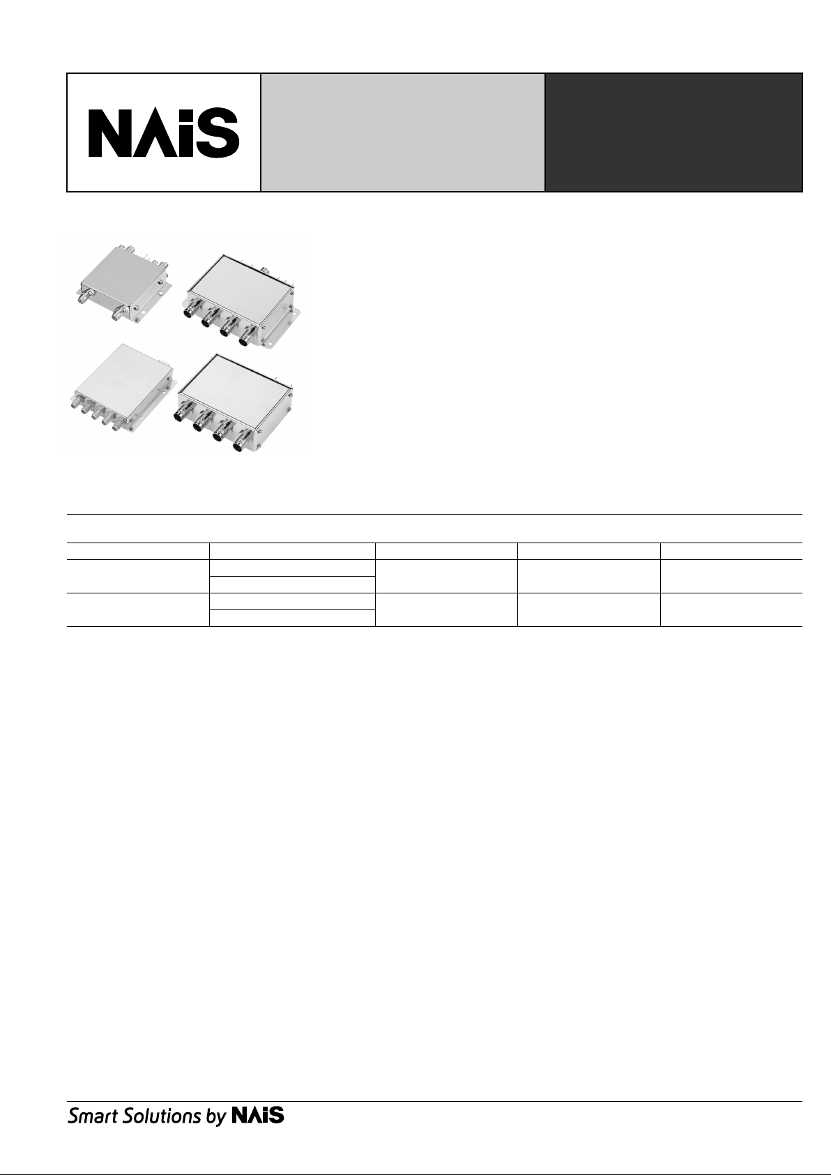
RZ-CO AXIAL
SWITCHES
TWO SERIES LINE-UP
OF IMPEDANCE 50Ω
AND 75
Ω
FEATURES
1. Two series line-up of impedance
50Ω and 75
Ω
2. Mechanical switch with superb
high-frequency characteristics.
3. Low profile type package
TYPICAL
APPLICATIONS
1. Cellular phone base stations
(IMT-2000)
2. Digital broadcast equipment
3. Test measurement equipment
STANDARD PRODUCTS
Circuit arrangement Impedance Frequency Connector
50Ω series
DPDT bypass
50
Ω
to 2.5 GHz SMA
SP4T
75Ω series
SP4T with termination
75
Ω
to 1.5 GHz BNC-J
Transfer
CUSTOM PRODUCTS
RZ coaxial switches can be customized.
From the point of view of pricing and deliv ery we recommend our standard products, ho w ever, you may contact us if you require a circuit configuration that differs from the products above. Please understand that, depending on the conditions, we may not be able to
customize in some cases.
RZ(ARZ1,2)
2
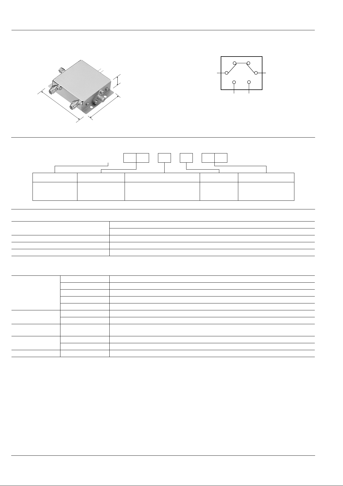
DPDT switch internal connection (bypass) type
(50Ω, to 2.5 GHz)
(mm inch)
45.0
1.772
56.0
2.205
15.0
0.591
ORDERING INFORMATION
ARZEx. 2 2 0 M
RZ coaxial switches 22: DPDT 0: Failsafe (50Ω) M: Bypass 05: 5
12: 12
24: 24
Product name Contact arrangement Operating function and impedance Added function Operating voltage, V DC
PRODUCT TYPES
Operating voltage (Vcc)
Part No.
Failsafe
5 V DC ARZ220M05
12 V DC ARZ220M12
24 V DC ARZ220M24
SPECIFICATIONS
1. Characteristics
High frequency
characteristics
(to 2.5 GHz,
Impedance 50Ω)
(Initial)
Impedance 50
Ω
Insertion loss Max. 1.0 dB
Isolation Min. 60 dB
V.S.W.R. Max. 1.5
Input power 20 W
Electrical
characteristics
Operating voltage Vcc±5%
Operate time 10 ms (excluding contact bounce time)
Expected life
(min. operations)
Electrical 5 × 10
4
Ambient temperature
Operate 0°C to +50°C 32°F to +122°F
Storage –10°C to +60°C +14°F to +140°F
Others Connector SMA
RZ(ARZ1,2)
3
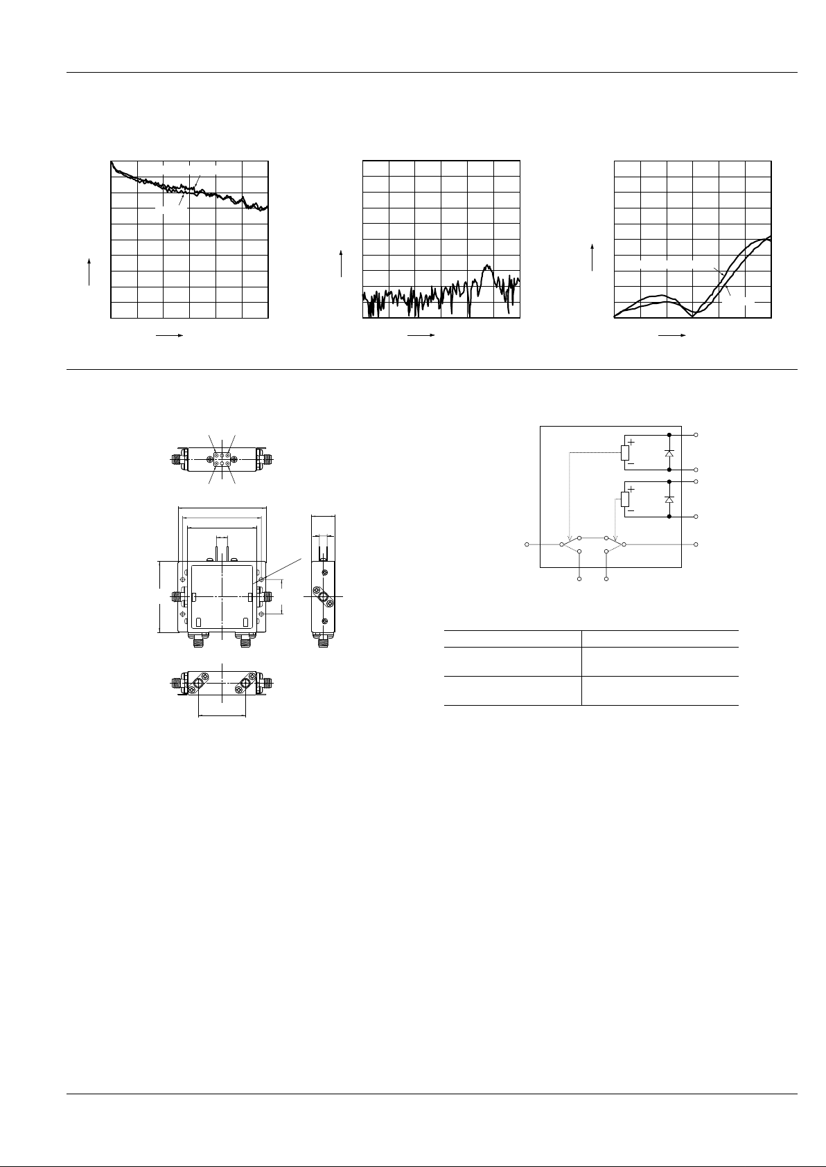
REFERENCE DATA
1. High frequncy characteristics
• Insertion loss
(Through and between terminal 1 to 3)
• Isolation
(Between terminal 1 to 3)
• V .S .W .R.
(Through and between terminal 1 to 3)
0.8
0.9
1.0
0
0.2
0.1
0.6
0.7
0.4
0.5
0.3
1GHz 3GHz2GHz
Frequency
Insertion loss, dB
Through
Between terminal 1 to 3
80
90
100
0
20
10
30
60
50
70
40
1GHz 3GHz2GHz
Frequency
Isolation, dB
1.1
1.0
1.5
1.2
1.4
1.3
1GHz 3GHz2GHz
Frequency
V.S.W.R.
Through
Between terminal 1 to 3
DIMENSIONS
mm inch
Equivalent circuit
Switching operation table
Note) Do not apply multiple control signals simultaneously.
7 .276
44 1.732
50 1.969
56 2.205
5
.197
14.9
.587
4-2.75 dia.
4-.108 dia.
30
1.181
43
12
+2+1
Control terminal +1 Control terminal +2
Control terminal –2Control terminal –1
45
1.772
22
.866
RF terminal path (SMA) Control terminal
3 to 4
(1, 2: no connection)
None
1 to 3
2 to 4
Control terminal +1, +2 → Vcc
Control terminal –1, –2 → Gnd
Control terminal +1
Control terminal –1
Control terminal +2
Control terminal –2
RF terminal 4RF terminal 3
RF terminal 1 RF terminal 2
 Loading...