

NAIS ARX124H, ARX1224, ARX1212, ARX1209, ARX1206 Datasheet
...
RX
SMALL MICRO WAVE RELAY
• Insertion loss
20.5
.807
12.4
.488
9.4
.370
mm inch
1. Excellent high frequency characteristics (~2.5GHz, Impedance 50 Ω )
• Insertion loss: 0.2 dB or less
• Isolation: 60 dB or more
SPECIFICATIONS
Contact
Arrangement
Contact material
Initial contact resistance
10W (2.5 GHz, Impedance
50 Ω, V.S.W.R. 1.2)
10mA 24V DC(resistive load)
Rating
High frequency
characteristics
(~2.5GHz,
Impedance 50Ω)
Expected
life (min.
operations)
Contact rating
Contact carrying power
Max. switching voltage
Max. switching current
Isolation
Insertion loss
V.S.W.R.(Return loss)
Input power
Mechanical (at 180 cpm)
10mA 24 V DC
(resistive load)
Electrical
10W 2.5 GHz,
Impedance 50Ω
Coil (at 20°C, 68°F)
Single side stable 200 mW
1 coil latching
2 coil latching
1 Form C
Gold
Max. 100 mΩ
Max. 20W(at 40°C,
V.S.W.R. 1.2, Average)
30 V DC
0.5 A DC
Min. 60 dB
Max. 0.2 dB
Max. 1.2 (Min. 20.8dB)
Max. 20W (at 40°C,
V.S.W.R. 1.2,Average)
5×10
3×10
Nominal operating power
200 mW
400 mW
0
0.1
0.2
Insertion loss, dB
0.3
0.4
0.5
300kHz 1.5GHz 2.5GHz3GHz
COM-NC
COM-NO
Frequency
Characteristics
Initial insulation resistance*
Initial
breakdown
voltage*
Operate time [Set time]*3 (at 20°C)
Release time (without diode) [Reset time]*
Temperature rise (at 20°C)*
Shock resistance
Vibration
resistance
6
Conditions for operation,
transport and storage*
(Not freezing and condensing
at low temperature)
Unit weight
Remarks
* Specifications will vary with foreign standards certification ratings.
1
Measurement at same location as “Initial breakdown voltage” section.
*
2
Detection current: 10mA
*
3
Nominal operating voltage applied to the coil, excluding contact bounce time.
*
4
By resistive method, nominal voltage applied to the coil: Contact carrying power:
*
20W, at 2.5GHz, Impedance 50Ω, V.S.W.R.&1.2
5
Half-wave pulse of sine wave: 11ms, detection time: 10µs.
*
6
Half-wave pulse of sine wave: 6ms
*
7
Detection time: 10µs
*
8
Refer to 5. Conditions for operation, transport and storage mentioned in
*
AMBIENT ENVIRONMENT (Page 61)
10
5
5
RX-RELA YS
• V.S.W.R./ Return loss: 1.2dB or less/
20.8dB or more
2. High sensitivity
• Nominal operating power: 200 mW
3. Small size
• Size: 20.5(L) × 12.4(W) × 9.4(H) mm
*Also available for unit support (contact us
Between open contacts
Between contact and coil
2
Between contact and
earth terminal
8
.807(L) × .488(W) × .370(H) inch
for more details).
1
4
Functional*
Destructive*
Functional*
Destructive
Ambient temp.
Humidity
Min. 100 MΩ (at 500 V DC)
500 Vrms
1,000 Vrms
500 Vrms
Max. 10ms (Approx. 6ms)
[Max. 10ms (Approx. 5ms)]
Max. 6ms (Approx. 3ms)
3
[Max. 10ms (Approx. 5ms)]
5
6
7
at double amplitude of 3 mm
at double amplitude of 5 mm
Max. 60°C
2
Min. 200 m/s
Min. 1,000 m/s2 {100 G}
10 to 55 Hz
10 to 55 Hz
–40°C to 60°C
–40°F to 140°F
5 to 85% R.H.
Approx. 5 g .18 oz
{20 G}
TYPICAL APPLICATIONS
• Cellular phone base station (W-CDMA,
FPLMTS, IMT-2000, PCS, DCS)
• Cellular phone-related measurement
devices (SP3T/SP4T switches, etc)
• Wireless LAN
• Wireless Local Loop
90
ORDERING INFORMATION
10RXAEx.
Product name
RX
Note: Standard packing; Carton: 50 pcs. Case 500 pcs.
Contact arrangement
1: 1 Form C
Operating function Coil voltage, V DC
0: Single side stable
1: 1 coil latching
2: 2 coil latching
12
03: 3
4H: 4.5
06: 6
09: 9
12: 12
24: 24
TYPES ANE COIL DATA (at 20°C 68°F)
• Single side stable type
Part No.
ARX1003
ARX104H
ARX1006
ARX1009
ARX1012
ARX1024
Nominal
voltage,
V DC
3 2.25 0.3 45 66.7 200 3.3
4.5 3.375 0.45 101 44.4 200 4.95
6 4.5 0.6 180 33.3 200 6.6
9 6.75 0.9 405 22.2 200 9.9
12 9 1.2 720 16.7
24 18 2.4 2,880 8.3 200 26.4
Pick-up
voltage, V DC
(max.)(initial)
Drop-out
voltage, V DC
(min.)(initial)
• 1 coil latching type
Part No.
ARX1103
ARX114H
ARX1106
ARX1109
ARX1112
ARX1124
Nominal
voltage,
V DC
3 2.25 3.3
4.5 3.375 4.95
6 4.5 6.6
9 6.75 9.9
12 9 13.2
24 18 26.4
Set
voltage, V DC
(max.)(initial)
Reset
voltage, V DC
(max.)(initial)
2.25
3.375
4.5
6.75
9
18
• 2 coil latching type
Part No.
ARX1203
ARX124H
ARX1206
ARX1209
ARX1212
ARX1224
Nominal
voltage,
V DC
3 2.25 3.3
4.5 3.375 4.95
6 4.5 6.6
9 6.75 9.9
12 9
24 18 26.4
Set
voltage, V DC
(max.)(initial)
Reset
voltage, V DC
(max.)(initial)
2.25
3.375
4.5
6.75
9 13.2
18
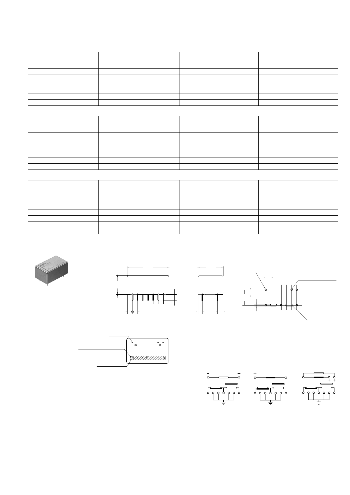
DIMENSIONS
Coil resistance,
Ω (±10%)
Coil resistance,
Ω (±10%)
45 66.7
101 44.4
180 33.3
405 22.2
720
2,880 8.3
Coil resistance,
Ω (±10%)
22.5
50.6
90
202.5
360
1,440
Nominal
operating current,
mA (±10%)
Nominal
operating current,
mA (±10%)
16.7
Nominal
operating current,
mA (±10%)
133.3
88.9
66.7
44.4
33.3
16.7
Nominal
operating power,
mW
200
Nominal
operating power,
mW
200
200
200
200
200
200
Nominal
operating power,
mW
400
400
400
400
400
400
RX
Max. allowable
voltage, V DC
13.2
Max. allowable
voltage, V DC
Max. allowable
voltage, V DC
mm inch
9.2
.362
0.2
.008
2.63
.104
2-0.6×0.3
2-.024×.012
Solder to the PC board earth.
7-0.40 to 0.45 dia.
7-.016 to .018 dia.
20.5
.807
2.54
.100
12.4
.488
3.0
.118
(2.04)
(.080)
7.62
.300
General tolerance: ±0.3 ±.012
Single side stable 1 coil latching 2 coil latching
14 13 12 11 10 9 8
NC
COM
(2.74)
(.108)
PC board pattern (Bottom view)
0.9 dia hole
.035 dia hole
2.54
.100
7.62
.300
0.90
.035
Schematic (Bottom view)
71
NO
RESET COM SET
(Reset condition)(Deenergized condition)
(2 coil latching type only)
R 0.45
Tolerance: ±0.1 ±.004
1
71
891011121314
1314
RESET COM SET
(Reset condition)
7
6
89101112
91
 Loading...