

RD
∗
∗
Transfer type is coming soon.
26.5GHz, 18GHz
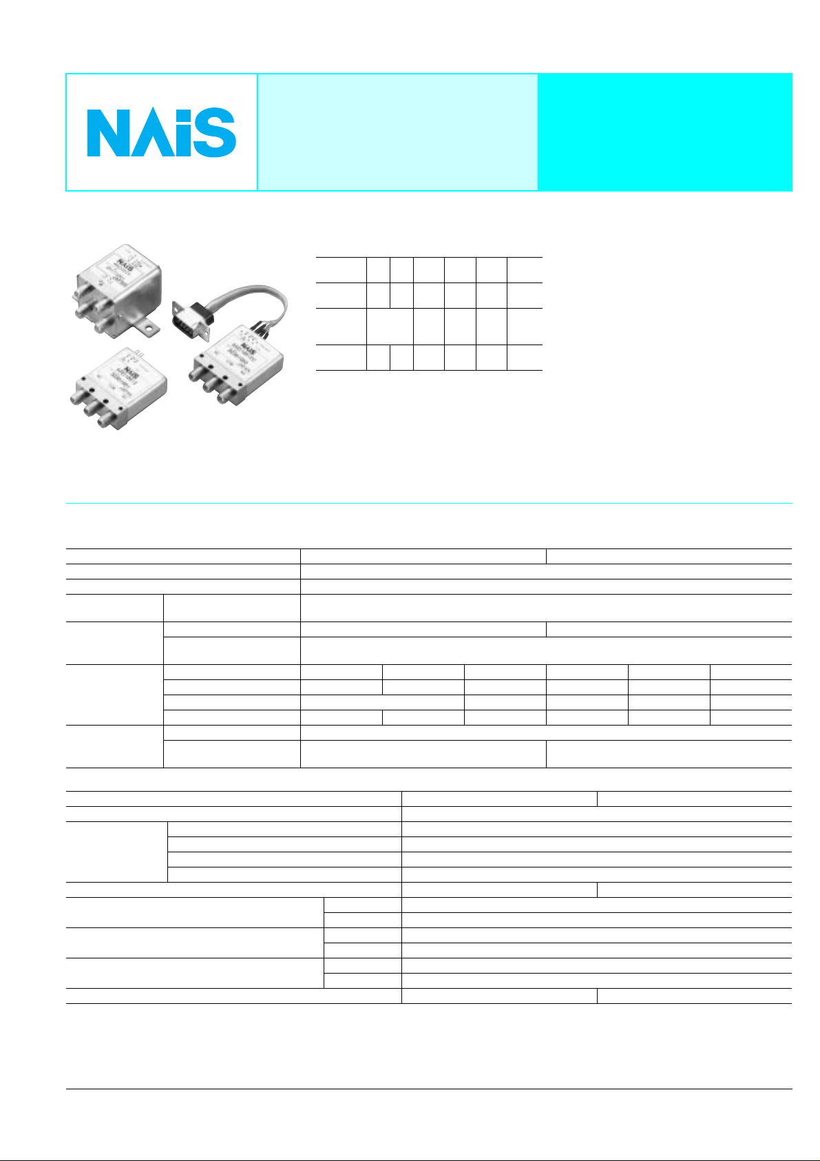
COAXIAL SWITCH
FEATURES
1. High frequency characteristics
(Impedance 50Ω)
Frequency
(GHz)
V.S.W.R.
(max.)
Insertion
loss
(dB. max.)
Isolation
(dB. min.)
*: 18 to 26.5GHz characteristics can be applied
26.5GHz type only
2. SPDT and transfer type available
3. High sensitivity
Nominal operating power:
840 mW (SPDT, Failsafe type)
1540 mW (Transfer, Failsafe type)
4. Long life: 5 × 10
–1 –4 –8 –12.4 –18 –26.5*
1.1 1.15 1.25 1.35 1.5 1.7
0.2 0.3 0.4 0.5 0.8
85 80 70 65 60 55
6
(SPDT)
RD COAXIAL
SWITCHES
TYPICAL APPLICATIONS
Wireless and mobile communication
infrastructure
• Cellular phone base stations
• Amplifier switching
Measurement instruments
• All types of inspection equipment
ATTENTION
Transfer type is coming soon.
SPECIFICATIONS
Contact
Arrangement SPDT Transfer
Contact material Gold plating
Initial contact resistance Max. 100m
Rating Contact input power*
Contact rating Max. 30V 100mA Max. 5V 100mA
Indicator rating
High frequency
characteristics
(Impedance 50Ω)
Expected life
(min. operation)
Initial contact resistance
(Measured by 5V 100mA)
V.S.W.R. (max.) 1.1 1.15 1.25 1.35 1.5 1.7
Insertion loss (dB, max.) 0.2 0.3 0.4 0.5 0.8
Isolation (dB, min.) 85 80 70 65 60 55
Mechanical (at 180 cpm) 5 × 10
Electrical (at 20 cpm)
1
(V.S.W.R 1.15 or less, no contact switching, ambient temperature 40°C [SPDT], 25°C [Transfer])
to 1 GHz 1 to 4 4 to 8 8 to12.4 12.4 to 18 18 to 26.5
5 × 10⁶ (5W, to 3GHz, impedance 50Ω,
V.S.W.R.; max. 1.2)
120W 3GHz
Max. 1
Characteristics
Initial insulation resistance*
Initial breakdown
3
voltage*
Operate time*4 (at 20°C) Max. 15ms Max. 20ms
Shock resistance
Vibration resistance
Conditions for operation, transport and storage*
(Not freezing and condensing at low temperature)
Unit weight (Approx.) 50g 1.76oz 110g 3.88oz
Remarks
*1Please verify the usability of input power under actual conditions because heat
generated from connectors can influence connection.
2
Measurement at same location as “Initial breakdown voltage” section.
*
*3Detection current: 10mA
4
Nominal operating voltage applied to the coil, excluding contact bounce time.
*
2
Between open contacts 500 Vrms for 1 min.
Between contact and coil 500 Vrms for 1 min.
Between contact and earth terminal 500 Vrms for 1 min.
Between coil and earth terminal 500 Vrms for 1 min.
Functional*
Destructive*
Functional*
Destructive 10 to 55 Hz at double amplitude of 5mm
8
Ambient temp –55°C to +85°C –67°F to +185°F
Humidity 5 to 85% R.H.
5
6
7
*5Half-wave pulse of sine wave: 11ms, detection time: 10µs.
*6Half-wave pulse of sine wave: 11ms
*
*8Refer to 4. Conditions for operation, transport and storage mentioned in NOTES.
SPDT Transfer
10 to 55 Hz at double amplitude of 3mm
7
Detection time: 10µs
Ω
Ω
6
106 (5W, to 3GHz, impedance 50Ω,
V.S.W.R.; max. 1.2)
Min. 1,000 M
500 m/s
1,000 m/s
Ω
2
2
1
RD
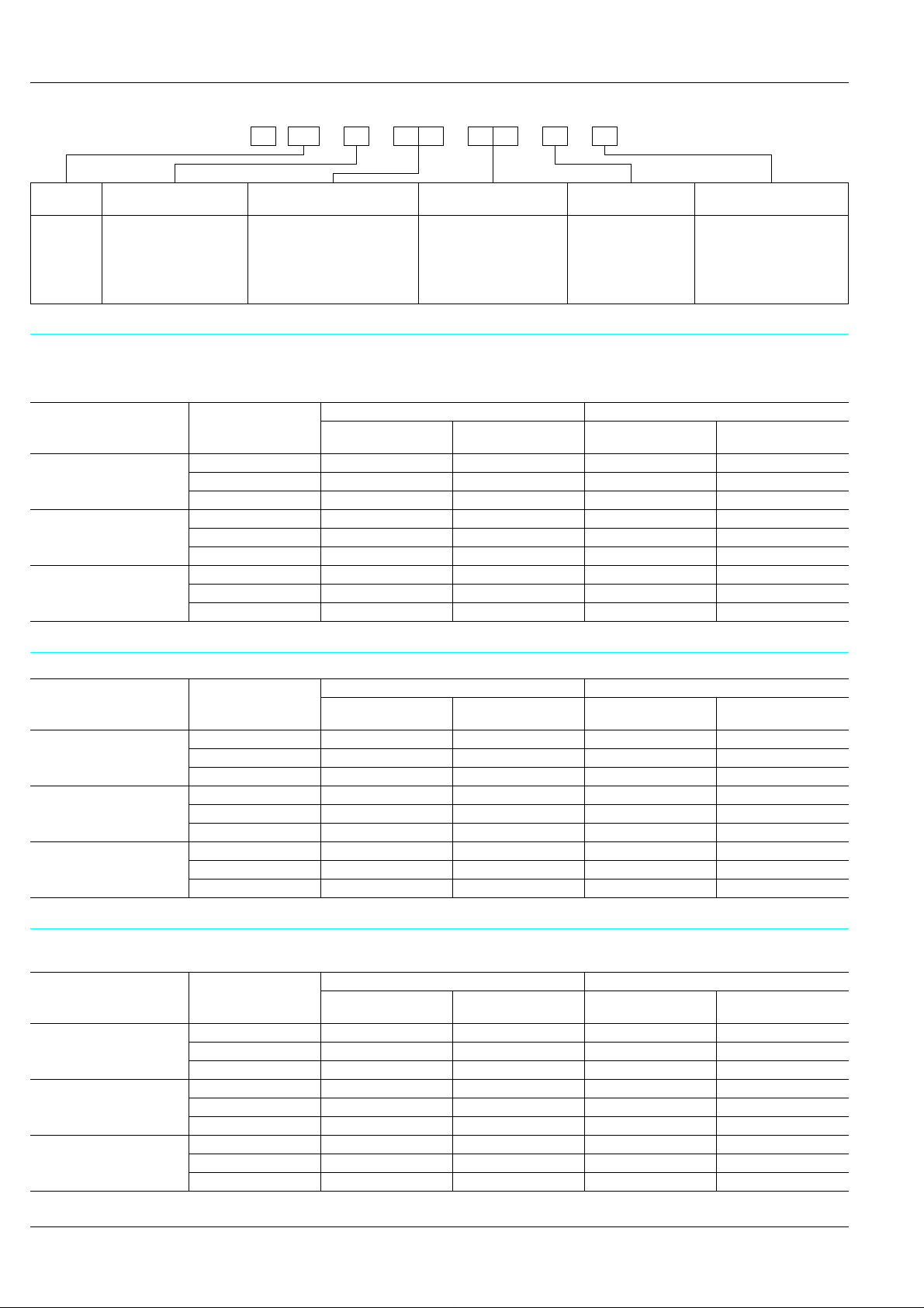
ORDERING INFORMATION
RDAEx.
Product
name
RD
Note: Sealed types are also available. (SPDT type only)
Frequency
1: to 18GHz (SPDT)
2: to 18GHz (Transfer)
5: to 26.5GHz (SPDT)
6: to 26.5GHz (Transfer)
Operating function
00: Failsafe
20: Latching
51: Latching with TTL driver
(with self cut-off function)
TYPES
1. SPDT
1) Solder terminal
Operating function
Failsafe
Latching
Latching with TTL driver
(with self cut-off function)
Note: Standard packing; Carton: 1 pc. Case: 20 pcs.
Nominal operating
voltage, V DC
4.5 ARD1004H ARD1004HQ ARD5004H ARD5004HQ
12 ARD10012 ARD10012Q ARD50012 ARD50012Q
24 ARD10024 ARD10024Q ARD50024 ARD50024Q
4.5 ARD1204H ARD1204HQ ARD5204H ARD5204HQ
12 ARD12012 ARD12012Q ARD52012 ARD52012Q
24 ARD12024 ARD12024Q ARD52024 ARD52024Q
5 ARD15105 ARD15105Q ARD55105 ARD55105Q
12 ARD15112 ARD15112Q ARD55112 ARD55112Q
24 ARD15124 ARD15124Q ARD55124 ARD55124Q
4H:
18GHz type 26.5GHz type
No HF datasheet
attached
Nominal operating
voltage, V DC
4.5V (Failsafe,
Latching type only)
05:
5V (Latching with
TTL driver type only)
12:
12V
24:
24V
HF datasheet
attached
Operation terminal
Nil:
Solder terminal
C:
Connector cable
(SPDT type only)
No HF datasheet
attached
HF data attached
Nil:
No HF test data
attached
Q:
HF test data attached
HF datasheet
attached
2) Connector cable
Operating function
Failsafe
Latching
Latching with TTL driver
(with self cut-off function)
Note: Standard packing; Carton: 1 pc. Case: 10 pcs.
Nominal operating
voltage, V DC
4.5 ARD1004HC ARD1004HCQ ARD5004HC ARD5004HCQ
12 ARD10012C ARD10012CQ ARD50012C ARD50012CQ
24 ARD10024C ARD10024CQ ARD50024C ARD50024CQ
4.5 ARD1204HC ARD1204HCQ ARD5204HC ARD5204HCQ
12 ARD12012C ARD12012CQ ARD52012C ARD52012CQ
24 ARD12024C ARD12024CQ ARD52024C ARD52024CQ
5 ARD15105C ARD15105CQ ARD55105C ARD55105CQ
12 ARD15112C ARD15112CQ ARD55112C ARD55112CQ
24 ARD15124C ARD15124CQ ARD55124C ARD55124CQ
2. T ransfer
1) Solder terminal
Operating function
Failsafe
Latching
Latching with TTL driver
(with self cut-off function)
Note: Standard packing; Carton: 1 pc. Case: 10 pcs.
Nominal operating
voltage, V DC
4.5 ARD2004H ARD2004HQ ARD6004H ARD6004HQ
12 ARD20012 ARD20012Q ARD60012 ARD60012Q
24 ARD20024 ARD20024Q ARD60024 ARD60024Q
4.5 ARD2204H ARD2204HQ ARD6204H ARD6204HQ
12 ARD22012 ARD22012Q ARD62012 ARD62012Q
24 ARD22024 ARD22024Q ARD62024 ARD62024Q
5 ARD25105 ARD25105Q ARD65105 ARD65105Q
12 ARD25112 ARD25112Q ARD65112 ARD65112Q
24 ARD25124 ARD25124Q ARD65124 ARD65124Q
18GHz type 26.5GHz type
No HF datasheet
attached
18GHz type 26.5GHz type
No HF datasheet
attached
HF datasheet
attached
HF datasheet
attached
No HF datasheet
attached
No HF datasheet
attached
HF datasheet
attached
HF datasheet
attached
2
COIL DATA (at 20°C 68°F)
1. SPDT
1) Failsafe type
Nominal operating voltage,
V DC
4.5 24.2 840
12 172 840
24 594 970
2) Latching type
Nominal operating voltage,
V DC
4.5 28.9 700
12 192 750
24 640 900
3) Latching with TTL driver type (with self cut-off function)
Nominal operating voltage,
V DC
5
12
24
2. T ransfer
1) Failsafe type
Nominal operating voltage,
V DC
4.5 13.2 1540
12 93.6 1540
24 345 1670
2) Latching type
Nominal operating voltage,
V DC
4.5 16.8 1200
12 115 1250
24 411 1400
3) Latching with TTL driver type (with self cut-off function)
Nominal operating voltage,
V DC
5
12
24
Coil resistance, Ω (±:10%) Nominal power consumption, mW
Coil resistance, Ω (±:10%) Nominal power consumption, mW
TTL logic level (see TTL logic level range)
ON OFF
2.4 to 5.5V 0 to 0.5V
Coil resistance, Ω (±:10%) Nominal power consumption, mW
Coil resistance, Ω (±:10%) Nominal power consumption, mW
TTL logic level (see TTL logic level range)
ON OFF
2.4 to 5.5V 0 to 0.5V
RD
Switching frequency
Max. 180 cpm
(ON time : OFF time = 1 : 1)
Switching frequency
Max. 180 cpm
(ON time : OFF time = 1 : 1)
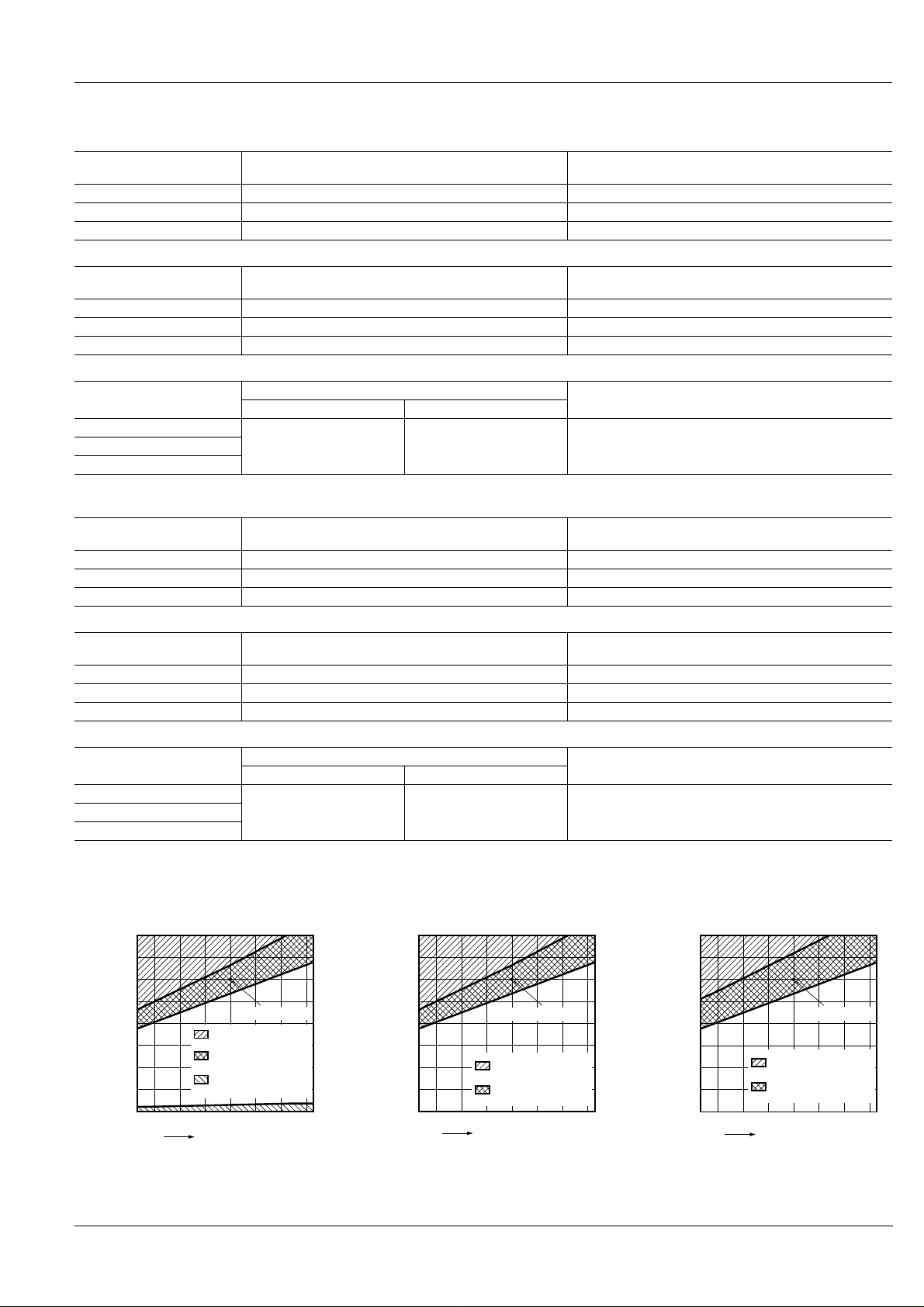
• Operating voltage range
1) Failsafe type 2) Latching type 3) Latching with TTL driver type
(with self cut-off function)
12
4.5V24
6
5.25
4.5
3.75
3
2.25
1.5
0.75
0
12
V
V
32
16
28
14
24
12
20
10
16
8
12
6
8
4
4
2
0
0
–55–40 0–20 20
Nominal voltage
Allowable range
for use
Recommended
operation voltage range
Recommended
release voltage range
Ambient temperature °C
4.5V24
V
V
32
16
6
28
14
5.25
24
12
4.5
20
10
3.75
16
8
3
12
6
2.25
8
4
1.5
4
2
0.75
0
0
8540 60
0
–55–40 0–20 20 8540 60
Nominal voltage
Allowable range
for use
Recommended
set/reset voltage range
Ambient temperature °C
5V24
6.67
5.83
5
4.17
3.33
2.5
1.67
0.83
0
12
V
V
32
16
28
14
24
12
20
10
16
8
12
6
8
4
4
2
0
0
–55–40 0–20 20 8540 60
Allowable range
for use
Recommended set/reset
voltage range
Ambient temperature °C
Nominal voltage
3

RD
4) TTL Logic level range
5.5
5
4
3
2.4
2
1
0.5
0
–55–40 0–20 20 8540 60
Ambient temperature °C
ON
OFF
DIMENSIONS
1. SPDT
1) Solder terminal
4.3
.169
39.0
1.535
4.5
.177
7.3
.287
3-SMA connector
2.1
.083
3.5
.138
3.5
.138
2.0
.079
11.2
.441
COMNC NO
GND
Serial No.
+
11.2
.441
22.4
.882
30.0
1.181
34.0
1.339
Indicator
Coil
3.5
.138
Solder terminal
2-3.1 dia.
2-.122 dia.
2-2.4 dia.
2-.094 dia.
7.0
.276
0.3
.012
7.2
.283
13.2
.520
Tolerance: ±0.3 ±.012
mm inch
Failsafe Latching Latching with TTL driver
(with self cut-off function)
Coil 1
Coil 2
COM12
GND 21
Serial No.
21 COM
Indicator
Coil
21 COM
Indicator terminal
Coil terminal
Logic 2
GND
Logic 1
V
211COM
Indicator
Coil
GND 2V
Serial No.
NC
GND
COMNC NO
GND
Serial No.
NOCOM
GND
Indicator
Coil
+
4

RD
2) Connector cable
5.95
.234
12.55
.494
1.2
.047
mm inch
Indicator Coil
Pin No.
123456789
Fail safe – NC COM NO – – GND + –
Latching – 1 COM 2 – – GND 1 2
Latching with
TTL driver
1
2345
Pin No.
6789
25.0
.984
30.8
1.213
– 1 COM 2 – V GND
D-sub connector
pin contact type
3.05 dia.
.120 dia.
Logic 1Logic
2
±10
110.0
±.394
4.331
39.0
1.535
4.5
.177
7.3
.287
3-SMA connector
2.1
.083
COMNC NO
GND
Serial No.
+
11.2
.441
22.4
.882
30.0
1.181
34.0
1.339
PVC wires
Indicator
Coil
2-3.1 dia.
2-.122 dia.
2-2.4 dia.
2-.094 dia.
13.2
.520
7.2
.283
Tolerance: ±0.3 ±.012
5

RD
V
GND
Logic 1
Logic 2
1
COM
2
Coil terminal Indicator terminal
2. T ransfer
3-3.80 dia.
3-.150 dia.
20.3
.799
9.65
.380
4-SMA connector
32.0
1.260
45.70
1.799
15.24
.600
32.0
1.260
16.2
.638
0.30
.012
mm inch
5.08
Max. 5.0
.197
10.15
.400
9.65
39.0
.380
1.535
7.2
.283
J2J1
16.2
.638
1 to 1.5
.039 to .059
J4J3
5.08
.200
2.00
.079
.200
5.08
.200
Solder terminal
55.5
2.185
Fail safe
Latching
Latching with TTL driver
Failsafe Latching Latching with TTL driver
(with self cut-off function)
Coil terminal Indicator terminal
GND
NC
COM
NO
Coil terminal Indicator terminal
GND
1
2
1
COM
2
Tolerance: ±0.3 ±.012
J1
J3
J2
J4
NC: J1-J2, J3-J4
NO: J1-J3, J2-J4
POS1: J1-J2, J3-J4
POS2: J1-J3, J2-J4
POS1: J1-J2, J3-J4
POS2: J1-J3, J2-J4
6

1GHz 4GHz
12.4GHz8GHz 18GHz 26.5GHz
Frequency
80
70
100
90
0
20
10
60
40
50
30
Isolation, dB
REFERENCE DATA
80
90
100
0
10
20
60
70
30
40
50
1GHz 4GHz
12.4GHz8GHz 18GHz 26.5GHz
Isolation, dB
Frequency
1-(1). High frequency characteristics (SPDT)
Sample: ARD10012
Measuring method: Measured with HP network analyzer (HP8510).
• V.S.W.R. • Insertion loss • Isolation
1.9
1.8
1.7
1.6
1.5
V.S.W.R.
1.4
1.3
1.2
1.1
1.0
1GHz 4GHz
12.4GHz8GHz 18GHz 26.5GHz
Frequency
1-(2). High frequency characteristics (Transfer)
Sample: ARD60012
Measuring method: Measured with HP network analyzer (HP8510).
• V.S.W.R. • Insertion loss • Isolation
1.9
1.8
1.7
1.6
1.5
V.S.W.R.
1.4
1.3
1.2
1.1
1.0
1GHz 4GHz
12.4GHz8GHz 18GHz 26.5GHz
Frequency
0
0.1
0.2
0.3
0.4
0.5
Insertion loss, dB
0.6
0.7
0.8
0.9
1.0
1GHz 4GHz
0
0.1
0.2
0.3
0.4
0.5
Insertion loss, dB
0.6
0.7
0.8
0.9
1.0
1GHz 4GHz
12.4GHz8GHz 18GHz 26.5GHz
Frequency
12.4GHz8GHz 18GHz 26.5GHz
Frequency
RD
7

RD
,
,
NOTES
1. Coil operating power
Pure DC current should be applied to the
coil. The wav e form should be rectangular.
If it includes ripple, the ripple factor should
be less than 5%.
However, check it with the actual circuit
since the characteristics may be slightly
different. The nominal operating voltage
should be applied to the coil for more than
50 ms to set/reset the latching type relay.
Please use the latching type for circuits
that are continually powered for long
periods of time.
2. Coil connection
When connecting coils, refer to the wiring
diagram to prevent mis-operation or
malfunction.
3. Connection of coil indicator and
washing conditions
1) The connection of coil indicator
terminal shall be done by soldering.
Soldering conditions
Max. 260°C 500°F (solder temp) within
10sec (soldering time)
Max. 350°C 662°F (solder temp) within
3sec (soldering time)
2) This product is not sealed type,
therefore washing is not allowed.
4. Usage, transport and storage
conditions
1) Ambient temperature, humidity, and
atmospheric pressure during usage,
transport, and storage of the relay:
(1) T emper ature:
–55 to +85°C –67 to +185°F
(2) Humidity: 5 to 85% RH
(Avoid freezing and condensation.)
The humidity range varies with the
temperature. Use within the range
indicated in the graph below.
(3) Atmospheric pressure: 86 to 106 kPa
Temperature and humidity range for
usage, transport, and storage:
Humidity, %RH
85
Tolerance range
(Avoid freezing when
,
used at temperatures
lower than 0°C 32°F)
–55
–67
(Avoid
condensation when
used at temperatures
higher than 0°C 32°F)
5
0
+32
Temperature, °C °F
,
+85
+185
2) Condensation
Condensation forms when there is a
sudden change in temperature under high
temperature and high humidity conditions.
Condensation will cause deterioration of
the relay insulation.
3) Freezing
Condensation or other moisture may
freeze on the relay when the temperature
is lower than 0°C 32°F. This causes
problems such as sticking of movable
parts or operational time lags.
4) Low temperature, low humidity
environments.
The plastic becomes brittle if the relay is
exposed to a low temperature, low
humidity environment for long periods of
time.
5) Low-temperature and low-humidity
atmosphere.
When exposed to low temperature and
low humidity for a long time, the relay’s
plastic casing may become breakable.
5. Other handling precautions.
1) The relay’s on/off service life is based
on standard test conditions (temperature:
15 to 35°C 59 to 95°F, humidity: 25 to
75%) specified in JIS C5442-1996. Life
will depend on many factors of your
system: coil drive circuit, type of load,
switching intervals, switching phase,
ambient conditions, to name a few.
2) Use the relay within specifications such
as coil rating, contact rating and on/off
service life. If used beyond limits, the rela y
may overheat, generate smoke or catch
fire.
3) Be careful not to drop the relay. If
accidentally dropped, carefully check its
appearance and characteristics before
use.
4) Be careful to wire the relay correctly.
Otherwise, malfunction, overheat, fire or
other trouble may occur.
5) The latching type rela y is shipped in the
reset position. But jolts during transport or
impacts during installation can move it to
the set position. It is , therefore, advisable
to build a circuit in
which the relay can be initialized (set and
reset) just after turning on the power.
6) If a relay stays on in a circuit for many
months or years at a time without being
activated, circuit design should be
reviewed so that the relay can remain
non-excited. A coil that receives current
all the time heats, which degrades
insulation earlier than expected. A
latching type relay is recommended for
such circuits.
7) For SMA connectors, we recommend a
torque of 0.90±0.1 N·m for installation,
which falls within the prescribed torque of
MIL-C-39012. Please be aware that
conditions might be different depending
on the connector materials and how it
interacts with surrounding materials.
8) Please do not use silicon based
substances such as silicon rubber, silicon
oil, silicon coatings and silicon fillings, in
the vicinity of the relay. Doing so may
cause volatile silicon gas to form which
may lead to contact failure due to the
adherence of silicon on the contacts when
they open and close in this atmosphere.
Please contact ..........
200303
8
These materials are printed on ECF pulp.
These materials are printed with earth-friendly vegetable-based (soybean oil) ink.
Matsushita Electric W orks, Ltd.
Automation Controls Company
K
Head Office: 1048, Kadoma, Kadoma-shi, Osaka 571-8686, Japan
K
Telephone: Japan (81) Osaka (06) 6908-1050
K
Facsimile: Japan (81) Osaka (06) 6908-5781
http://www.nais-e.com/
COPYRIGHT © 2003 All Rights Reserved
Specifications are subject to change without notice. Printed in Japan.
 Loading...