

NAIS ARA220A4H, ARA220A24, ARA220A1H, ARA220A06, ARA220A05 Datasheet
...
00A 032AEx.
Operating function
0: Single side stable
1: 1 coil latching
2: 2 coil latching
Contact arrangement
2: 2 Form C
RA
Product name
RA
Note: Standard packing; Carton: 40 pcs. Case 1,000 pcs.
0: Standard
type
(B.B.M)
A: Surface-mount
terminal
Type of operation
Terminal shape
1H: 1.5
03: 3
4H: 4.5
05: 5
06: 6
09: 9
12: 12
24: 24
48: 48
Coil voltage, V DC
RA
MICROWAVE RELAY
FOR ATTENUATOR
RA-RELA YS
CIRCUIT
14.70
.579
9.7
.382
5.9
.232
• Insertion loss; Max. 0.3dB
• Isolation; Min. 20dB (Between open
Min. 30dB (Between contact
• V.S.W.R.; Max. 1.2
mm inch
2. Surface mount terminal
This relay is a surface-mounted model
FEATURES
1. High frequency characteristics
with excellent high-frequency properties. In addition, it can use a microstrip
(Impedance 50 Ω , ~1.0GHz)
SPECIFICATIONS
Contact
Arrangement 2 Form C
Contact material Gold-clad silver alloy
Initial contact resistance Max. 75m Ω
10mA 10 V DC
1A 30 V DC
Max. 3W(at 1.0GHz, imped-
ance 50 Ω , V .S .W .R. max.1.2)
Min. 20dB
Min. 30dB
Max. 3W(at 1.0GHz, imped-
ance 50 Ω , V .S .W .R. max.1.2)
140mW (1.5 to 12V)
200mW (24V)
300mW (48V)
70 mW (1.5 to 12V)
100mW (24V)
140mW (1.5 to 12V)
200mW (24V)
8
7
10
5
10
Rating
High frequency
characteristics
(~1GHz,
Impedance 50 Ω )
Nominal
operating
power
Expected
life (min.
operation)
Contact rating (resistive)
Contact carrying power
Max. switching voltage 30 V DC
Max. switching current 1A
Between
open con-
Isolation
tacts
Between
contact
sets
Insertion loss Max. 0.3dB
V.S.W.R. Max. 1.2
Input power
Single side stable
1 coil latching
2 coil latching
Mechanical (at 180 cpm) 10
10mA 10 V
DC(resisElectrical
(at 20 cpm)
tive load)
1A 30 V DC
(resistive
load)
contacts)
sets)
line in the base circuit design which
spares the labor of machining the base.
3. Low profile small type
9.7(W) × 14.7(L) × 5.9(H) mm
.382(W) × .579(L) × .232(H) inch
4. High sensitivity: 140 mW nominal
operating power
5. High contact reliability
Electrical life: Min. 10
7
(10mA 10V DC)
Characteristics
Initial insulation resistance *
1
Between open contacts
Between contact
Initial breakdown
voltage *
2
sets
Between contact
and coil
Between contact
and earth terminal
Operate time [Set time] *
Release time (without diode) [Reset time]
3
*
(at 20 ° C)
Temperature rise (at 20 ° C) *
Shock resistance
3
(at 20 ° C)
4
Functional *
Destructive *
Functional *
5
6
7
Vibration resistance
Destructive
Conditions for oper-
ation, transport and
storage *
8
(Not freezing and
condensing at low
Ambient temp
Humidity 5 to 85% R.H.
temperature)
Unit weight Approx. 2g .07oz
Remarks
* Specifications will vary with foreign standards certification ratings.
1
*
Measurement at same location as “Initial breakdown voltage” section.
2
Detection current: 10mA
*
3
*
Nominal operating voltage applied to the coil, excluding contact bounce time.
4
By resistive method, nominal voltage applied to the coil: 3W contact carrying
*
power: at 1.0GHz, Impedance 50 Ω , V .S.W.R. Max.1.2
5
*
Half-wave pulse of sine wave: 11ms, detection time: 10 µ s.
6
Half-wave pulse of sine wave: 6ms
*
7
*
Detection time: 10 µ s
8
Refer to 5. Conditions for operation, transport and storage mentioned in
*
AMBIENT ENVIRONMENT (Page 61)
Min. 100 M Ω (at 500 V DC)
750 Vrms for 1 min.
1,000 Vrms for 1 min.
1,000 Vrms for 1 min.
1,000 Vrms for 1 min.
Max. 4ms (Approx. 2ms)
[Max. 4ms (Approx. 2ms)]
Max. 4ms (Approx. 1ms)
[Max. 4ms (Approx. 2ms)]
Max. 60 ° C
2
500 m/s
1,000 m/s
2
10 to 55 Hz at double
amplitude of 3mm
10 to 55 Hz at double
amplitude of 5mm
–40 ° C to +85 ° C
–40°F to +185°F
TYPICAL APPLICATIONS
• Measurement instruments
Oscilloscope attenuator circuit
80
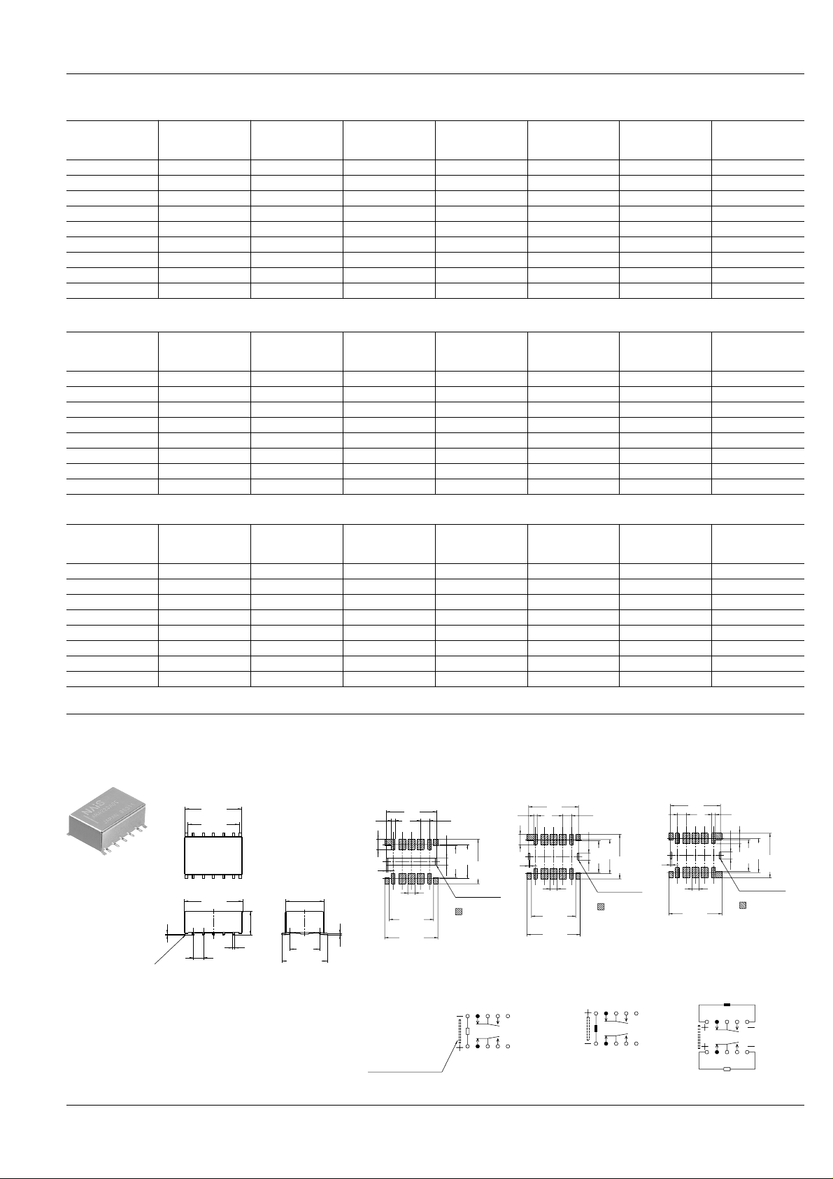
ORDERING INFORMATION
Ω ( ±
2.54
.100
1.0
.039
2.94
.116
0.3
.012
2.00
.079
2.00
.079
earth
for glue pad
14.0
.551
12.40
.488
14.90
.587
8.90
.350
9.56
.376
12.50
.492
Suggested Mounting Pads (Top view)
Single side stable
2.54
.100
1.0
.039
2.94
.116
0.3
.012
2.00
.079
earth
for glue pad
14.0
.551
2.00
.079
12.40
.488
14.90
.587
9.56
.376
12.50
.492
8.90
.350
1 coil latching
2.54
.100
1.0
.039
2.94
.116
0.3
.012
2.00
.079
2.00
.079
earth
for glue pad
8.90
.350
9.56
.376
12.50
.492
14.90
.587
14.0
.551
2 coil latching
5.90
.232
0.50
.020
2.54
.100
Soldering with
PC board earth
(4 ribs)
0~0.30
0~.012
9.70
.382
0.25
.010
12.90
.508
14.30
.563
14.70
.579
7.62
.300
11.5±0.5
.453±.020
12345
678910
1 coil latching
Schematic (Top view)
(Reset condition)
1
01
2345
6789
2 coil latching
(Reset condition)
12345
678910
Direction indication
Single side stable
(Deenergized condition)
Tolerance: ±0.1
±.004
Tolerance: ±0.3 ±.012
Ω ( ±
±
Ω ( ±
±
±
TYPES ANE COIL DATA (at 20°C 68°F)
• Single side stable type
Part No.
voltage,
V DC
ARA200A1H 01.5 1.125 0.15 00.16.0 93.8 140 2.25
ARA200A03 03.0 2.250 0.30 00.64.3 46.7 140 4.50
ARA200A4H 04.5 3.375 0.45 0.1450 31.0 140 6.75
ARA200A05 05.0 3.750 0.500.1780 28.1 140 7.50
ARA200A06 06.0 4.500 0.600.2570 23.3 140 90.0
ARA200A09 09.0 6.750 0.900.5790 15.5 140 13.50
ARA200A12 12.0 90.00 1.20 1,028.0 11.7 140 180.0
ARA200A24 24.0 18.0000 2.40 2,880.0 08.3 200 360.0
ARA200A48 48.0 36.0000 4.80 7,680.0 06.3 300 57.60
• 1 coil latching type
Nominal
Part No.
ARA210A1H 01.5 1.125 01.125 0.032.0 46.9 070 2.25
ARA210A03 03.0 2.25002.2500.128.6 23.3 070 4.50
ARA210A4H 04.5 3.375 03.375 0.289.3 15.6 070 6.75
ARA210A05 05.0 3.75003.7500.357.0 14.0 070 7.50
ARA210A06 06.0 4.500 04.500 0.514.0 11.7 070 9.00
ARA210A09 09.0 6.75006.750 1,157.0 07.8 070 13.50
ARA210A12 12.0 9.000 09.000 2,057.0 05.8 070 18.00
ARA210A24 24.0 18.000 18.000 5,760.0 04.2 100 36.00
Nominal
voltage,
V DC
Pick-up voltage,
V DC (max.)
(initial)
Set voltage,
V DC (max.)
(initial)
Drop-out
voltage, V DC
(min.)(initial)
Reset voltage,
V DC (max.)
(initial)
Coil resistance,
10%)
Coil resistance,
10%)
Nominal
operating current,
mA (
10%)
Nominal
operating current,
10%)
mA (
Nominal
operating power ,
mW
Nominal
operating power ,
mW
Max. allowable
voltage, V DC
Max. allowable
voltage, V DC
RA
• 2 coil latching type
Part No.
voltage,
V DC
ARA220A1H 01.5 01.125 01.125 .0016.0 93.8 140 2.25
ARA220A03 03.0 02.25002.250 .0064.3 46.7 140 4.50
ARA220A4H 04.5 03.375 03.375 .0145.0 31.0 140 6.75
ARA220A05 05.0 03.75003.750.0178.0 28.1 140 7.50
ARA220A06 06.0 04.500 04.500 .0257.0 23.3 140 9.00
ARA220A09 09.0 06.75006.750.0579.0 15.5 140 13.50
ARA220A12 12.0 09.000 09.000 1,028.0 11.7 140 18.00
ARA220A24 24.0 18.000 18.000 2,880.0 08.3 200 36.00
Nominal
Set voltage,
V DC (max.)
(initial)
Reset voltage,
V DC (max.)
(initial)
Coil resistance,
10%)
Nominal
operating current,
10%)
mA (
Nominal
operating power ,
mW
DIMENSIONS
Max. allowable
voltage, V DC
mm inch
81
 Loading...