

NAIS AQZ262 Datasheet
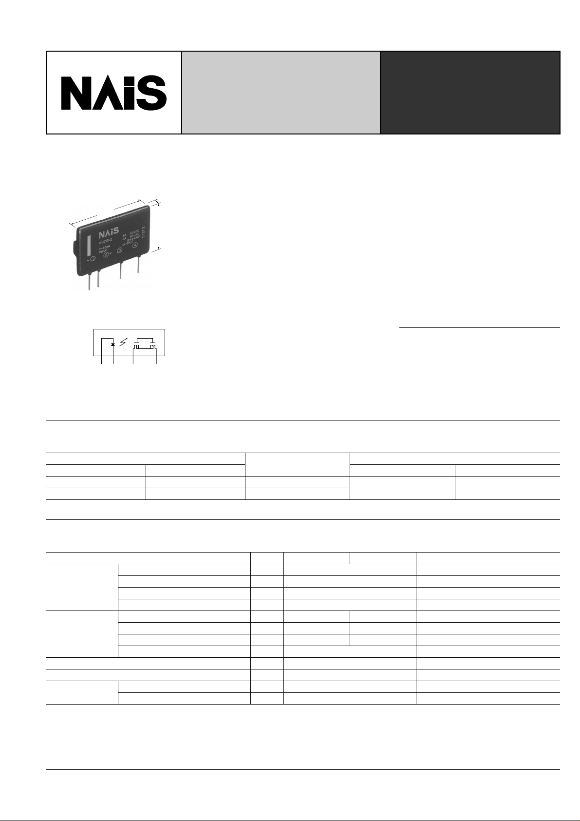
Max. 43.0
1.693
12 3 4
–+
Max. 9.0
.354
Max. 32.0
1.260
POWER PhotoMOS RELAYS
(High capacity type)
FEATURES
1. High capacity type power photoMOS
relay .
Can switch a wide range of currents and
voltages. Can control various types of
loads, from very small loads to a maximum 6A AC/DC current for sequencers,
motors, and lamps.
2. Low ON resistance and high sensitivity.
Low ON resistance of less than 50 mW on
a par with mechanical relays (AQZ262).
High sensitivity LED operate current of 3
mm inch
mA (at 25 ° C 77 ° F ).
3. AC/DC dual use
Bi-directional control is possible. There is
no need to differentiate depending on the
load as was necessary with the conventional SSR.
4. 4-pin SIL type.
4-pin SIL type of (L) 43.0 mm × (W) 9.0
mm × (H) 32.0 mm (L) 1.693 inch × (W)
.354 inch × (H) 1.260 inch.
PhotoMOS
RELAYS
5. Low-level off state leakage current
In contrast to the SSR with an off state
leakage current of several milliamps, the
PhotoMOS relay features a v ery small off
state leakage current of only 10mA even
at the rated load voltage.
6. Controls low-level analog signals
The triac, photocoupler, or SSR cannot be
used to control signals of less than several hundred mV. The high capacity type
power PhotoMOS relay f eature extremely
low closed-circuit offset voltage to enable
control of low-level analog signals without
distortion.
TYPICAL APPLICATIONS
• Mercury relay replacement
• Railroad, traffic signals
• Compact motors, lamps, heaters
• OA equipment
• Measurement instruments
TYPES
AC/DC type
Output rating*
Load voltage Load current Inner carton Outer carton
60 V 6.0 A AQZ262
400 V 1.0 A AQZ264
* Indicate the peak AC and DC values.
Part No.
20 pcs 200 pcs
Packing quantity
RATING
1) Absolute maximum ratings (Ambient temperature: 25 ° C 77 ° F)
Item Symbol AQZ262 AQZ264 Remarks
LED forward current I
Input
Output
Total power dissipation P
I/O isolation voltage Viso 1,500 V AC
Temperature limits
LED reverse voltage V
Peak forward current I
Power dissipation P
Load voltage (Peak AC) V
Continuous load current (Peak AC) I
Peak load current I
Power dissipation P
Operating T
Storage Tstg –40 ° C to +100 ° C –40 ° F to 212 ° F
FP
peak
F
R
in
L
L
out
T
opr
60 V 400 V
6.0 A 1.0 A
10.0 A 3.0 A 100 ms (1shot), V
–40 ° C to +85 ° C –40 ° F to 185 ° F Non-condensing at low temperatures
50 mA
3 V
1 A f = 100Hz, Duty factor = 0.1%
75 mA
3.0 W
3.0 W
= DC
L
219
■
■
■
AQZ262, 264
2) Electrical characteristics (Ambient temperature: 25 ° C 77 ° F)
Item Symbol AQZ262 AQZ264 Remarks
LED operate current
Input
LED turn off current
LED dropout voltage
On resistance
Output
Off state leakage current Maximum I
Turn on time*
Switching speed
Turn off time*
Transfer
characteristics
I/O capacitance
Initial I/O isolation resistance Minimum R
Maximum operating frequency Maximum — 0.5 cps
Note: Recommendable LED forward current I
*Turn on/off time
Typical
Maximum 3.0 mA
Minimum
Typical 0.9 mA
Typical
Maximum 1.5 V
Typical
Maximum 0.05 Ω
Typical
Maximum 10 ms
Typical
Maximum 3.0 ms
Typical
Maximum 4.0 pF
= 5 to 10 mA. For type of connection, see page 35.
F
I
I
R
T
T
C
Fon
Foff
V
Leak
on
off
iso
iso
1.0 mA
0.4 mA
F
on
1.16 V (1.25 V at I
0.036 Ω
F
= 50 mA)
1.0 Ω
1.4 Ω
10 µ A
5 ms 4 ms
0.32 ms 0.14 ms
2.0 pF
1,000 M Ω
L
I
= 100 mA
L
V
= 10 V
L
I
= 100 mA
L
V
= 10 V
F
I
= 10 mA
F
I
= 10 mA
L
I
= max.
Within 1 s on time
F
I
= 0
= max.
L
V
I
F
= 10 mA
= 100 mA
L
I
V
= 10 V
L
I
F
= 10 mA
= 100 mA
L
I
V
= 10 V
L
f = 1 MHz
V
= 0
B
500 V DC
I
= 10 mA
F
Duty factor = 50%
I
= Max., V
L
= Max.
L
Input
Output 10%
Ton
Toff
REFERENCE DATA
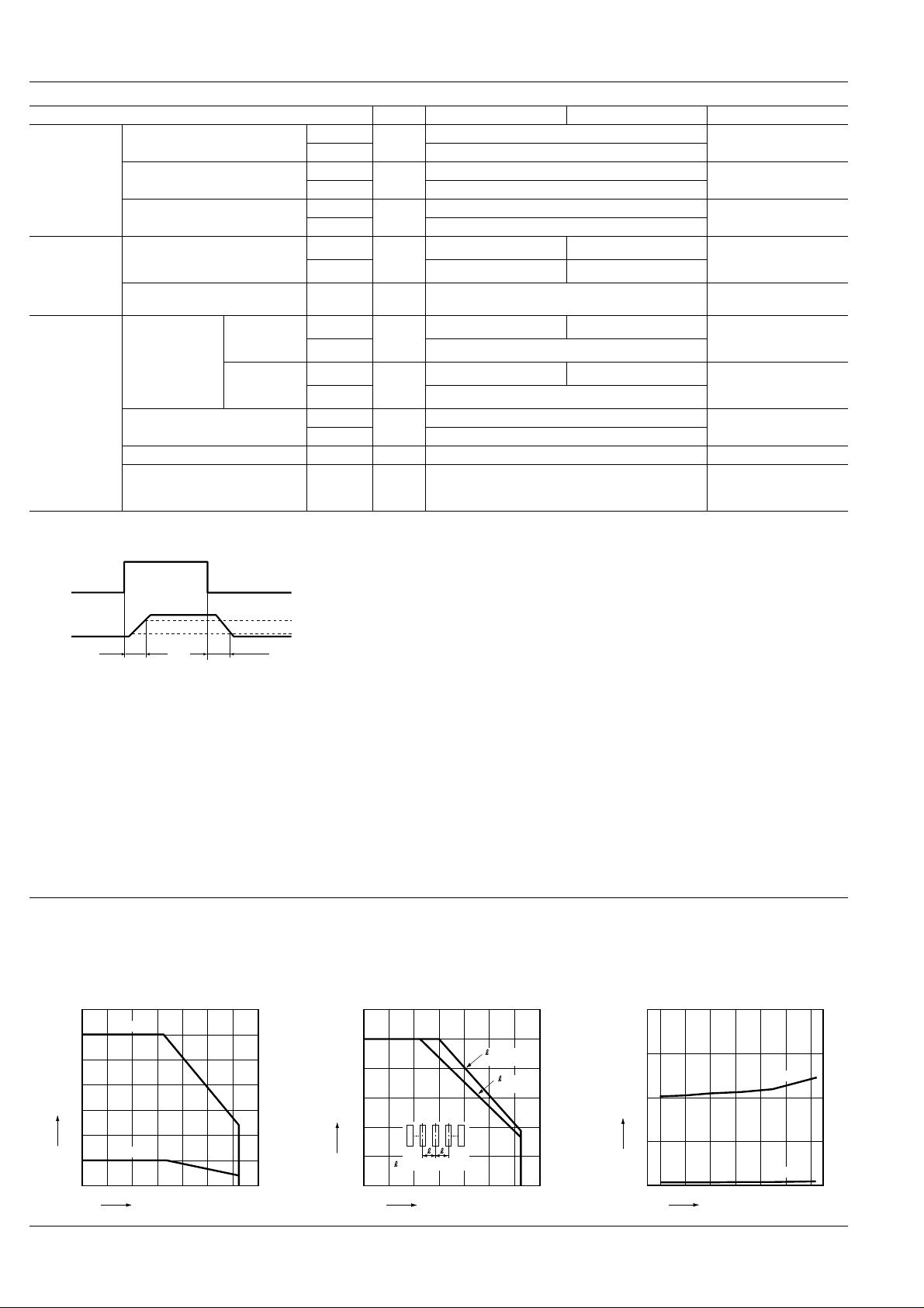
1. Load current vs. ambient temperature
characteristics
Allowable ambient temperature: –40 ° C to +85 ° C
7
6
5
4
Load current, A
3
2
1
0
AQZ262
AQZ264
0–40 20 40 60
Ambient temperature, °C
–40 ° F to +185 ° F
8085
100–20
90%
For Dimensions, see Page 29.
For Schematic and Wiring Diagrams, see Page 35.
For Cautions for Use, see Page 40.
2. Load current vs. ambient temperature characteristics in adjacent mounting
L
I
: Load current;
(max.): Maximum continuous load current
L
I
120
100
80
60
(max.)×100, %
L
/I
L
I
40
20
0
=Adjacent mounting pitch
–20
0–40 20 40 60 100
Ambient temperature, °C
=20mm
.787 inch
=10mm
.394 inch
8085
3. On resistance vs. ambient temperature characteristics
LED current: 10 mA;
Continuous load current: 6A (DC)(AQZ262)
2
1.5
1
On resistance, Ω
0.5
0
1A (DC)(AQZ264)
0–40 20 40 60
–20
Ambient temperature, °C
AQZ264
AQZ262
8085
220
 Loading...