

NAIS AQY410EH, AQY414EHAZ, AQY414EHAX, AQY414EHA, AQY414EH Datasheet
...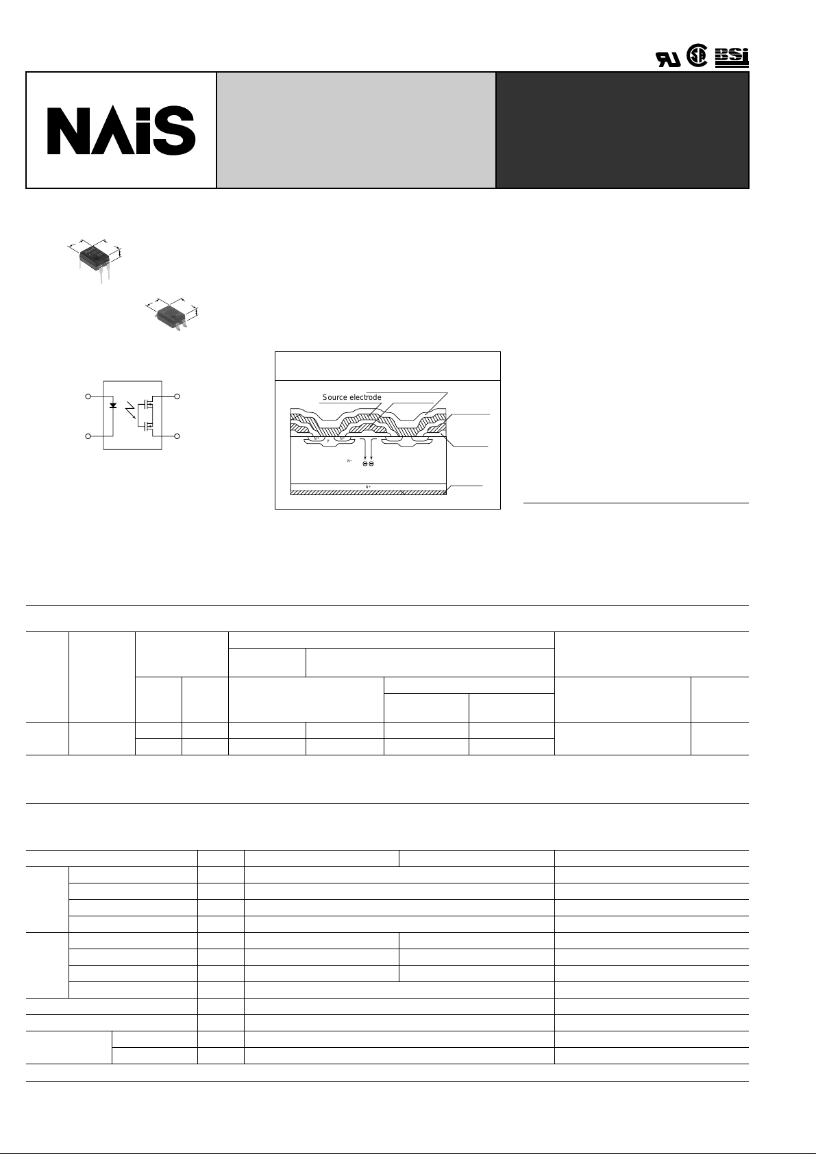
AQY41 ❍ EH
4.78
.188
6.4
.252
3.2
.126
1
2
4.78
.188
TESTING
GU (General Use)-E Type
PhotoMOS
1-Channel (Form B)
4-pin T ype
RELAYS
FEATURES
1. Low on resistance for normallyclosed type
This has been realized thanks to the builtin MOSFET processed by our proprietary
6.4
.252
2.9
.114
mm inch
4
3
method, DSD (Double-diffused and Selective Doping) method.
Cross section of the normally-closed type
of power MOS
Cross section of the normally-closed type of
power MOS
Source electrode
N+N
+
+
P
–
N
Passivation membrane
Gate electrode
+
N+N
+
P
+
N
Intermediate
insulating
membrane
Gate
oxidation
membrane
Drain
electrode
3. Compact 4-pin DIP size
The device comes in a compact
(W)6.4 × (L)4.78 × (H)3.2mm
(W).252 × (L).188 × (H).126inch, 4-pin DIP
size
4. Controls low-level analog signals
PhotoMOS relays feature extremely low
closed-circuit offset voltage to enable
control of low-level analog signals without
distortion.
5. High sensitivity, low ON resistance
Can control a maximum 0.13 A load current with a 5 mA input current. Lo w ON resistance of 18 Ω (AQY410EH). Stable
operation because there are no metallic
contact parts.
6. Low-level off state leakage current
2. Reinforced insulation 5,000 V type
More than 0.4 mm internal insulation distance between inputs and outputs. Conforms to EN41003, EN60950 (reinforced
insulation).
TYPICAL APPLICATIONS
• Modem
• T elephone equipment
• Security equipment
• Sensors
TYPES
Part No.
Output rating*
I/O isolation
Type
AC/DC
type
*Indicate the peak AC and DC values.
Note: For space reasons, the initial letters of the product number "AQY", the SMD terminal shape indicator "A" and the package type indicator "X" and "Z" are omitted from
Reinforced
the seal.
voltage
5,000 V
Load
voltage
Load
current
350 V 130 mA AQY410EH AQY410EHA AQY410EHAX AQY410EHAZ
400 V 120 mA AQY414EH AQY414EHA AQY414EHAX AQY414EHAZ
Through hole
terminal
Tube packing style
Surface-mount terminal
Tape and reel packing style
Picked from the
Picked from the
1/2-pin side
3/4-pin side
1 tube contains 100 pcs.
1 batch contains 1,000 pcs.
Packing quantity
Tube
Tape and
reel
1,000 pcs.
RATING
1. Absolute maximum ratings (Ambient temperature: 25 ° C 77 ° F)
Item Symbol AQY410EH (A) AQY414EH (A) Remarks
LED forward current I
LED reverse voltage V
Input
Peak forward current I
Power dissipation P
Load voltage (peak AC) V
Output
Continuous load current I
Peak load current I
Power dissipation P
Total power dissipation P
I/O isolation voltage V
T emperature
limits
Operating T
Storage T
FP
peak
F
R
50 mA
3 V
1 A f = 100 Hz, Duty factor = 0.1%
in
L
L
350 V 400 V
0.13 A 0.12 A
0.4 A 0.3 A 100 ms (1 shot), V
out
T
iso
opr
stg
–40 ° C to +85 ° C –40 ° F to +185 ° F Non-condensing at low temperatures
–40 ° C to +100 ° C –40 ° F to +212 ° F
75 mW
500 mW
550 mW
5,000 V AC
L
= DC
122
Ambient temperature, °C
Operate (OFF) time, ms
0
1
0.5
1.5
2
2.5
–40 –20
3
0204060
80 85
2. Electrical characteristics (Ambient temperature: 25 ° C 77 ° F)
Item Symbol AQY410EH (A) AQY414EH (A) Condition
LED operate
(OFF) current
Input
LED reverse
(ON) current
LED dropout
voltage
On resistance
Output
Off state leakage current
Operate (OFF)
time*
Reverse (ON)
Transfer char-
time*
acteristics
I/O capacitance
Initial I/O isola-
tion resistance
Note: Recommendable LED forward current I
Typical
Maximum 3.0 mA
Minimum
Typical 1.3 mA 1.2 mA
Typical
Maximum 1.5 V
Typical
Maximum 25 Ω
Maximum I
Typical
Maximum 3.0 ms
Typical
Maximum 1.0 ms
Typical
Maximum 1.5 pF
Minimum R
I
Foff
Fon
I
F
V
on
R
Leak
T
off
T
on
C
iso
iso
= 5 to 10mA. For type of connection, see page 32.
F
18 Ω 26 Ω
35 Ω
10 µ
1.4 mA 1.3 mA
0.4 mA
1.14 (1.25 V at I
F
= 50 mA)
A
1.0 ms 0.8 ms
0.3 ms 0.2 ms
0.8 pF
1,000M Ω
*Operate/Reverse time
■
■
■
AQY41 ❍ EH
L
I
=Max.
L
I
=Max.
F
I
= 5 mA
F
I
= 0 mA
L
I
= Max.
Within 1 s on time
F
I
= 5 mA
= Max.
L
V
I
= 0 mA-->5 mA
F
I
= Max.
L
I
= 5 mA-->0 mA
F
I
= Max.
L
f =1MHz
V
=0
B
500 V DC
For Dimensions, see Page 27.
For Schematic and Wiring Diagrams, see Page 32.
For Cautions for Use, see Page 36.
REFERENCE DATA
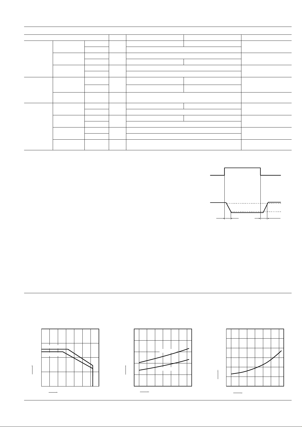
1. Load current vs. ambient temperature characteristics
Allowable ambient temperature: –40 ° C to +85 ° C
–40 ° F to +185 ° F
200
2. On resistance vs. ambient temperature characteristics
Measured portion: between terminals 3 and 4;
LED current: 0 mA; Load voltage: Max.(DC);
Continuous load current: Max. (DC)
50
Input
Output
Toff
3. Operate (OFF) time vs . ambient temper ature
characteristics
LED current: 5 mA; Load voltage: Max. (DC);
Continuous load current: Max. (DC)
10%
90%
Ton
Load current, mA
150
100
50
0
AQY410EH
AQY414EH
0204060
Ambient temperature, °C
8085
40
30
On resistance, Ω
20
10
0
100–40 –20
–40 –20
AQY414EH
AQY410EH
0204060
Ambient temperature, °C
8085
123
 Loading...