

NAIS AQY221N2VY, AQY221N2VW Datasheet
UL
pending
CSA
pending
RF (Radio Frequency)
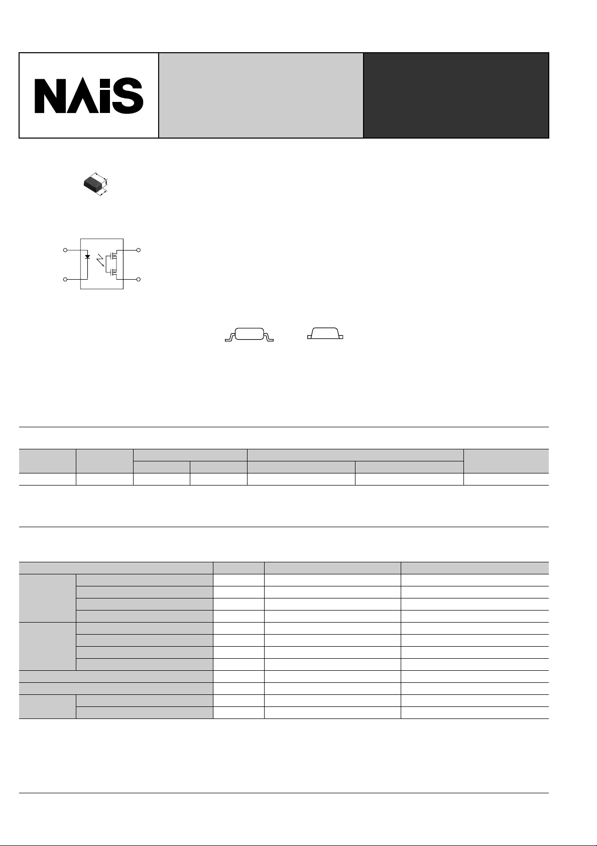
C ✕ R 10 SSOP Type
(by)
FEATURES
4.45
.175
1.80
.071
2.65
.104
mm inch
1
2
4
3
1. Reduced package size
Lower surface has been reduced 60%
and mounting space 40% compared to
conventional 4-pin SOP type.
2. Lower output capacitance and onresistance
Output capacitance(C): 1.0pF (typ.)
ON resistance(R): 9.5Ω (typ.)
3. Mounting space has been reduced
and output signals have been
improved by using new flat lead
PhotoMOS
RELAYS
TYPICAL APPLICATIONS
Measuring and testing equipment
1. Test equipment
IC tester, Liquid crystal driver tester,
semiconductor performance tester
2. Board tester
Bear board tester, In-circuit tester,
function tester
3. Medical equipment
Ultrasonic wave diagnostic machine
4. Multi-point recorder
Warping, thermo couple
terminals.
Conventional
SOP type
SSOP
Flat lead
4. High speed switching
Turn on time: 0.02ms
Turn off time: 0.02ms
TYPES
Circuit
arrangement
1 Form A AC/DC type 40 V 120 mA AQY221N2VY AQY221N2VW 3,500 pcs.
* Indicate the peak AC and DC values.
Notes: (1)Tape package is the standard packing style.
(2)For space reasons, the initial letters of the product number “AQY and V”, the package type indicator “Y” and “W” are omitted from the seal.
Type
Output rating* Tape and reel packing style
Load voltage Load current Picked from the 1/4-pin side Picked from the 2/3-pin side
Packing quantity
in tape and reel
RATING
1. Absolute maximum ratings (Ambient temperature: 25°C 77°F)
Item Symbol AQY221N2V Remarks
LED forward current I
Input
Output
Total power dissipation P
I/O isolation voltage V
Temperature
limits
LED reverse voltage V
Peak forward current I
Power dissipation P
Load voltage (peak AC) V
Continuous load current (peak AC) I
Peak load current I
Power dissipation P
Operating T
Storage T
FP
peak
F
R
in
L
L
out
T
iso
opr
stg
–40°C to +85°C –40°F to +185°F Non-condensing at low temperatures
–40°C to +100°C –40°F to +212°F
50mA
3V
1A f=100 Hz, Duty factor=0.1%
75mW
40V
0.12A Peak AC,DC
0.3A 100 ms (1 shot), VL= DC
250mW
300mW
1,500V AC
2
2. Electrical characteristics (Ambient temperature: 25°C 77°F)
0
5
10
15
20
25
02040608085-40 -20
On resistance, Ω
Ambient temperature, °C
Item Symbol AQY221N2V Condition
LED operate current
Input
LED turn off current
LED dropout voltage
On resistance
Output
Output capacitance
Off state leakage current
Turn on time*
Switching speed
Transfer
Turn off time*
characteristics
I/O capacitance
Initial I/O isolation resistance Minimum R
Note: Recommendable LED forward current IF = 5 mA.
For type of connection, see Page 5.
Typical
Maximum 3.0 mA
Minimum
Typical 0.9 mA
Typical
Maximum 1.5 V
Typical
Maximum 12.5
Typical
Maximum 1.5 pF
Typical
Maximum 10 nA
Typical
Maximum 0.5ms
Typical
Maximum 0.2 ms
Typical
Maximum 1.5 pF
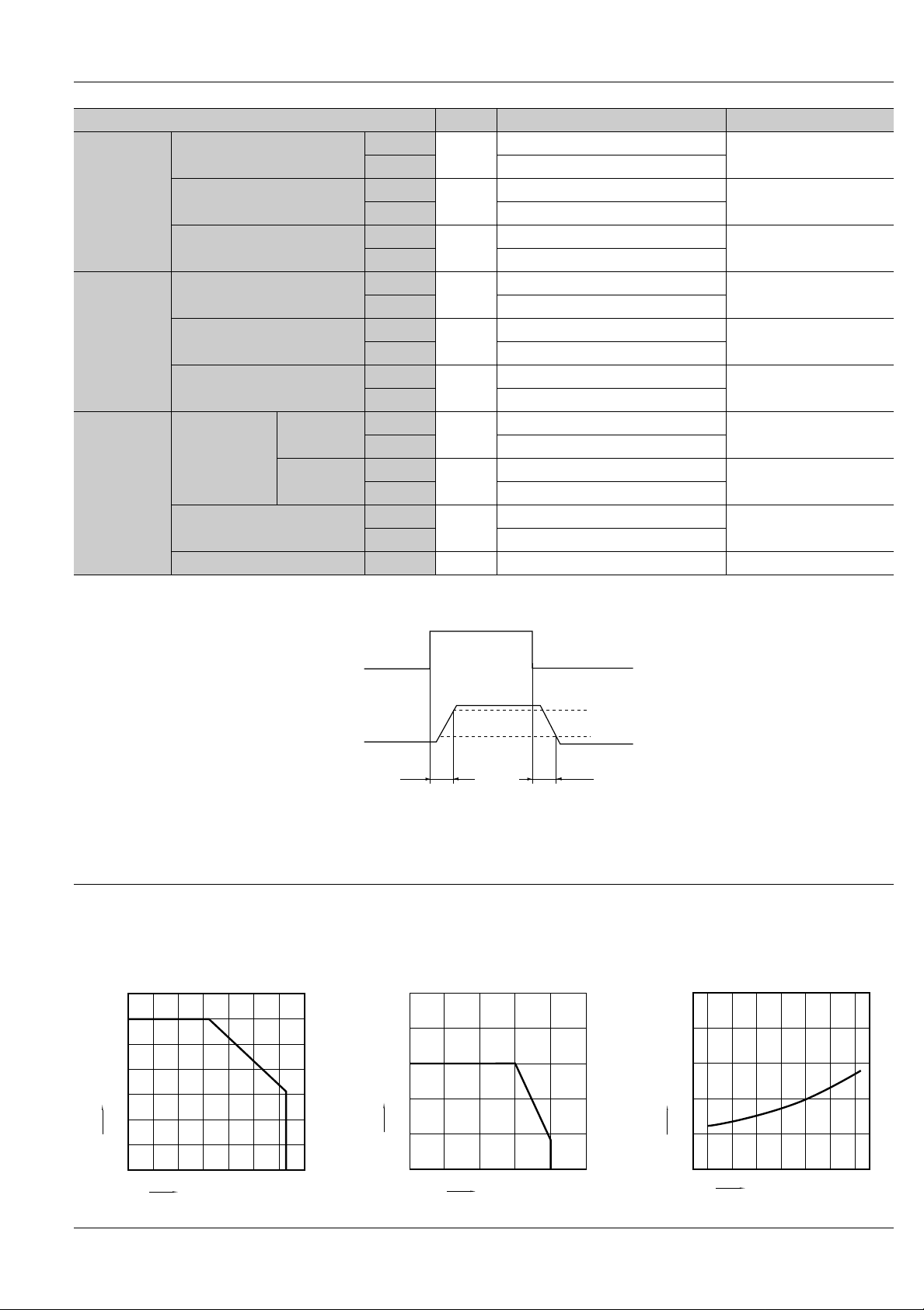
*Turn on/Turn off time
I
I
R
C
I
T
T
C
Fon
Foff
V
Leak
AQY221N2V
1.0 mA
0.2 mA
F
on
out
1.14 V (1.35 V at IF = 50mA)
9.5
Ω
Ω
1.0 pF
0.01 nA
on
off
iso
iso
0.02 ms
0.02ms
0.8 pF
1,000M
Ω
IL = 80 mA
IL = 80 mA
IF = 5mA
IF = 5mA
IL = 80 mA
Within 1 s on time
IF = 0
VB = 0 V
f = 1 MHz
IF = 0
VL = Max.
IF = 5mA
VL = 10V
RL = 125
Ω
IF = 5mA
VL = 10V
RL = 125
Ω
f = 1MHz
VB = 0
500V DC
Input
90%
Output
Ton
10%
Toff
REFERENCE DATA
1. Load current vs. ambient temperature
characteristics
Allowable ambient temperature: –40°C to +85°C
140
120
100
80
60
Load current, mA
40
20
0
0204060
Ambient temperature, °C
–40°F to +185°F
8085
100-40 -20
2. Load current vs. Load voltage characteristics
Ambient temperature: 25°C 77°F
200
160
120
Load current, mA
80
40
0
10 20 30 40 500
Load voltage, V
3. On resistance vs. ambient temperature
characteristics
Measured portion: between terminals 3 and 4
LED current: 5 mA; Load voltage: Max. (DC);
Load current: 80mA (DC)
3
 Loading...