

NAIS AQY210KSZ Datasheet
GU (General Use) Type SOP
Series 1-Channel (Form A)
PhotoMOS
with Short Circuit Protection
4-Pin T ype
RELAYS
FEATURES
3. Tape and reel
The device comes standard in a tape and
reel (1,000 pcs./reel) to facilitate automatic insertion machines.
4. Controls low-level analog signals
5. Low-level off state leakage current
TYPICAL APPLICATIONS
• T elephone equipment
• Modem
• Measuring and Testing equipment
• Security equipment
• Industrial equipment
• Traffic signal control
4.3±0.2
.169±.008
1
2
4.4±0.2
.173±.008
2.1±0.2
.083±.008
mm inch
1. Short circuit protection
When the output current exceeds a fixed
amount, it is cut and the off state is maintained. The relay can be restored by turning off the input current and then turning it
back on.
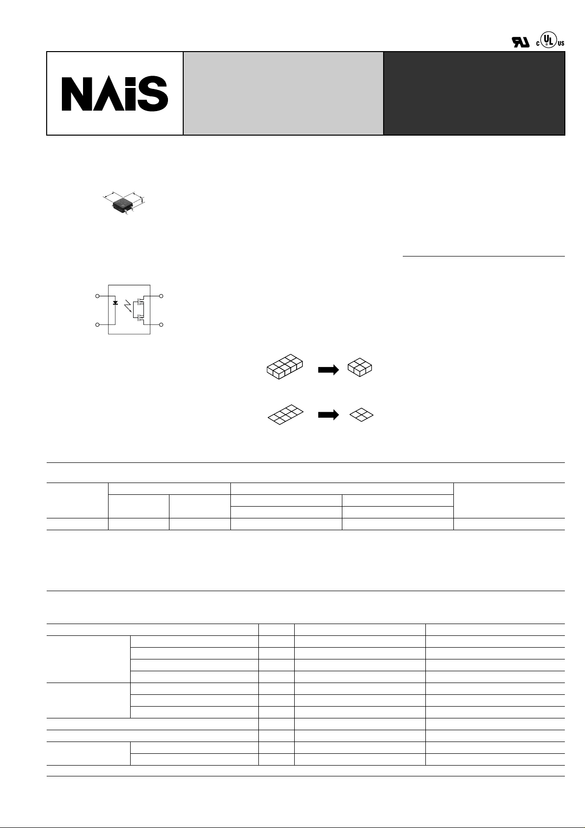
2. SO package 4-Pin type in super miniature design
The device comes in a super-miniature
SO package 4-Pin type measuring (W)
4.3 × (L) 4.4 × (H) 2.1 mm (W).169 × (L)
4
.173 × (H) .083 inch—approx. 70% of the
volume and 70% of the footprint size of
SO package 6-pin type PhotoMOS Re-
3
lays.
(4-pin)(6-pin)
Approx. 70%
Volume
Approx. 70%
Footprint
TYPES
Output rating* Part No.
Type
AC/DC type 350 V 120 mA AQY210KSX AQY210KSZ 1,000 pcs.
* Indicate the peak AC and DC values.
Notes: (1) Tape package is the standard packing style. Also available in tube. (Part No. suffix “X” or “Z” is not needed when ordering; Tube: 100 pcs.;
Case: 2,000 pcs.)
(2) For space reasons, the initial letters of the product number “AQY” and “S” are ommited on the product seal.
The package type indicator “X” and “Z” are omitted from the seal. (Ex. the label for product number AQY210KS is 210K).
Load voltage Load current
Picked from the 1/2-pin side Picked from the 3/4-pin side
1 Form A 1 Form A
Packing quantity
in tape and reel
RATING
1. Absolute maximum ratings (Ambient temperature: 25 ° C 77 ° F)
Item Symbol AQY210KS Remarks
LED forward current I
Input
Output
Total power dissipation P
I/O isolatiom voltage V
Temperature limits
LED reverse voltage V
Peak forward current I
Power dissipation P
Load voltage (peak AC) V
Continuous load current (peak AC) I
Power dissipation P
Operating T
Storage T
F
R
FP
in
L
L
out
T
iso
–40 ° C to +85 ° C –40 ° F to +185 ° F Non-condensing at low temperatures
opr
–40 ° C to +100 ° C –40 ° F to +212 ° F
stg
50 mA
3 V
1 A f = 100 Hz, Duty factor = 0.1%
75 mW
350 V
0.12 A
300 mW
350 mW
1,500 V AC
97
AQY210KS
2. Electrical characteristics (Ambient temperature: 25 ° C 77 ° F)
Item Symbol AQY210KS Condition
LED operate current
Input
LED turn off current
LED dropout voltage
On resistance
Off state leakage current Maximum I
Output
Over current
Cut off current
protection
Detection time Typical T
Turn on time*
Transfer
Turn off time*
characteristics
I/O capacitance
Initial I/O isolation resistance Minimum R
Note: Recommendable LED forward current I
Typical
Maximum 3.0 mA
Minimum
Typical 1.0 mA
Typical
Maximum 1.5 V
Typical
Maximum 35 Ω
Minimum
Typical 200 mA
Maximum 240 mA
Typical
Maximum 2 ms
Typical
Maximum 1 ms
Typical
Maximum 1.5 pF
= 5 mA. For type of connection, see Page 31.
F
■
■
■
I
Fon
Foff
I
F
V
on
R
1.13 V (1.32 V at I
1.1 mA
0.3 mA
23.5 Ω
F
= 50mA)
L
I
= 120 mA
L
I
= 120 mA
F
I
= 5 mA
F
I
= 5 mA
= 120 mA
L
I
Within 1 s on time
I
= 0 mA
F
V
= 350 V
L
I
= 5 mA
F
Within 20ms on time
I
= 5 mA
F
V
= 350V DC short circuit
L
I
= 5 mA
F
I
= 120 mA
L
I
= 5 mA
F
I
= 120 mA
L
f = 1 MHz
V
= 0
B
500 V DC
C
Leak
I
T
T
shut
shut
1 µ A
160 mA
50 µ s
on
off
iso
iso
0.7 ms
0.07 ms
0.8 pF
1,000 M Ω
*Turn on/Turn off time
Input
Output
Ton
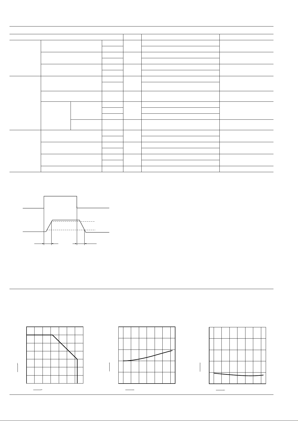
REFERENCE DATA
1. Load current vs. ambient temperature characteristics
Allowable ambient temperature: –40 ° C to +85 ° C
140
120
100
80
60
Load current, mA
40
20
0
0204060
Ambient temperature, °C
98
–40 ° F to +185 ° F
8085
100–40 –20
90%
10%
Toff
For Dimensions, see Page 28.
For Schematic and Wiring Diagrams, see Page 31.
For Cautions for Use, see Page 36.
2. On resistance vs. ambient temperature characteristics
Measured portion: between terminals 3 and 4;
LED current: 5 mA; Load voltage: Max. (DC)
Load current: Max.(DC)
50
40
30
On resistance, Ω
20
10
0
02040608085–40 –20
Ambient temperature, °C
3. Turn on time vs. ambient temperature characteristics
Measured portion: between terminals 3 and 4;
LED current: 5 mA; Load voltage: 10V (DC);
Continuous load current: Max.(DC)
4
3
2
Turn on time, ms
1
0
–40 –2050204060
Ambient temperature, °C
80
85
 Loading...