

NAIS AQX21444 Datasheet
GU (General Use) Type
PhotoMOS
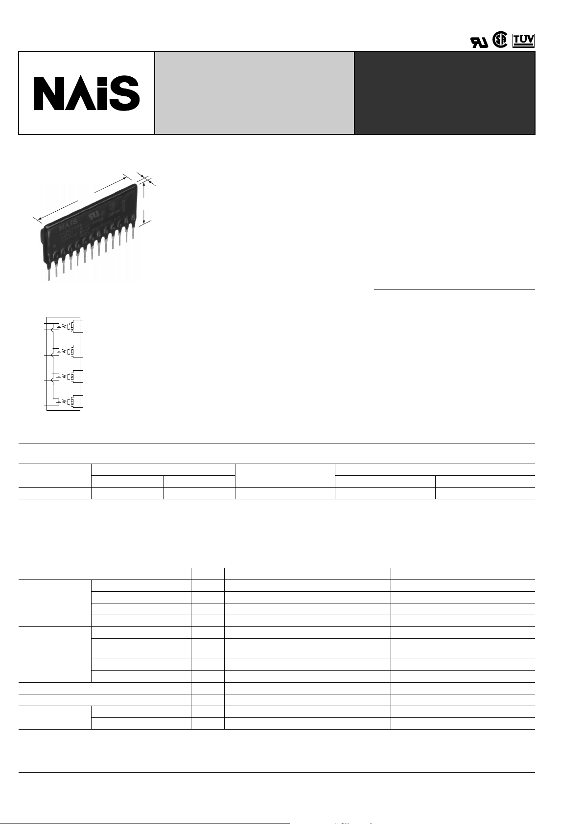
[Multi-Channel (4-Channel)
T ype]
RELAYS
FEATURES
1. 4-circuit (4-Form A) of GU
PhotoMOS Relay in a compact and slim
13 pin SIL
2. Applicable for 4 Form A use, as well
as 4 independent 1 Form A
34 max.
1.339
5 max.
.197
18 max.
.709
3. Controls low-level analog signals
PhotoMOS relays feature extremely low
closed-circuit offset voltage to enable
control of low-level analog signals without
distortion.
4. Low-level off state leakage current
mm inch
(Typical 100 pA at 100 V load voltage)
5. Optical coupling for extremely high
Q
W
E
R
T
Y
U
I
O
P
{
}
q
Input 1: DC–
W
Input 2: DC–
E
Input 3: DC–
R
Input 4: DC–
T
Output 1 (N.O.):
Y
DC or AC
Output 1 (N.O.):
U
DC or AC
Output 2 (N.O.):
I
DC or AC
Output 2 (N.O.):
O
DC or AC
Output 3 (N.O.):
P
DC or AC
Output 3 (N.O.):
{
DC or AC
Output 4 (N.O.):
}
DC or AC
Output 4 (N.O.):
q
DC or AC
Input Common: DC+
Q
isolation
6. Eliminates the need for a counter
electromotive protection diode in the
drive circuit on the input side
7. PC board layout is simplified
8. Eliminates the need for a separate
power supply to drive the power MOSFET
9. Low thermal electromotive force
(Approx. 1 µ V)
10. No restriction on mounting direction
11. No arc, no bounce, no noise
TYPICAL APPLICATIONS
• T elecomm unication equipment
• High speed inspection machine, Scanner, IC checker
• Robots
TYPES
Output rating*
Load voltage Load current Inner case Outer carton
AC/DC type 400 V 80 mA AQX21444 20 pcs. 200 pcs.
*Indicate the peak AC and DC values.
Part No.
Packing quantity
RATINGS
1. AC/DC type
1. Absolute maximum ratings (Ambient temperature: 25 ° C 77 ° F)
Item Symbol AQX21444 Remarks
LED forward current I
Input
Output
Total power dissipation P
I/O isolation voltage V
Temperature limits
LED reverse voltage V
Peak forward current I
Power dissipation P
Load voltage (peak AC) V
Continuous load current I
Peak load current I
Power dissipation P
Operating T
Storage T
FP
peak
F
R
in
L
L
out
T
iso
opr
stg
–40 ° C to +85 ° C –40 ° F to +185 ° F Non-condensing at low temperatures
–40 ° C to +100 ° C –40 ° F to +212 ° F
50 mA
3 V
1 A f = 100 Hz, Duty factor = 0.1%
75 mW
400 V
80 mA (100 mA)
0.3 A 100 ms (1 shot), V
1,450 mW
1,500 mW
1,500 V AC
( ): in case of using only 1 channel
Peak AC, DC
= DC
L
60
■
■
■
1 µ
AQX21444
2. Electrical characteristics (Ambient temperature: 25 ° C 77 ° F)
Item Symbol AQX21444 Condition
Input
Output
LED operate current
LED turn off current
LED dropout voltage
On resistance
Typical
Maximum 3 mA
Minimum
Typical 1.0 mA
Typical
Maximum 1.5 V
Typical
Maximum 50 Ω
Off state leakage current Maximum I
I
I
V
R
Leak
Fon
Foff
F
on
1.14 V (1.25 V at I
Typical
Maximum 2 ms
Typical 0.29 ms
T
on
Maximum 1 ms
Typical
Maximum 0.5 ms
Typical
Maximum 8.0 pF
Minimum R
T
off
C
iso
iso
Transfer
characteristics
Switching
Turn on time*
speed
Turn off time*
I/O capacitance
Initial I/O isolation
resistance
Vibration resistance Minimum — 10 to 55 Hz at double amplitude of 3 mm 2 hours for 3 axes
Shock resistance Minimum — 4,900 m/s
Note: Recommendable LED forward current I
= 5 mA. For type of connection, see page 34.
F
*Turn on/Turn off time
1.1 mA
0.4 mA
30 Ω
F
= 50 mA)
L
I
= 80 mA
L
I
= 80 mA
F
I
= 5 mA
F
I
= 5 mA
L
I
= 80 mA
Within 1 s on time
F
I
A
0.52 ms
0.19 ms
4.0 pF
1,000 M Ω
2
{500 G} 1 ms 3 times for 3 axes
= 0 mA
= 400 V
L
V
I
= 5 mA
F
I
= 80 mA
L
I
= 10 mA
F
I
= 80 mA
L
I
= 5 mA or 10 mA
F
I
= 80 mA
L
f = 1 MHz
V
= 0
B
500 V DC
Input
Output 10%
Ton
Toff
REFERENCE DATA
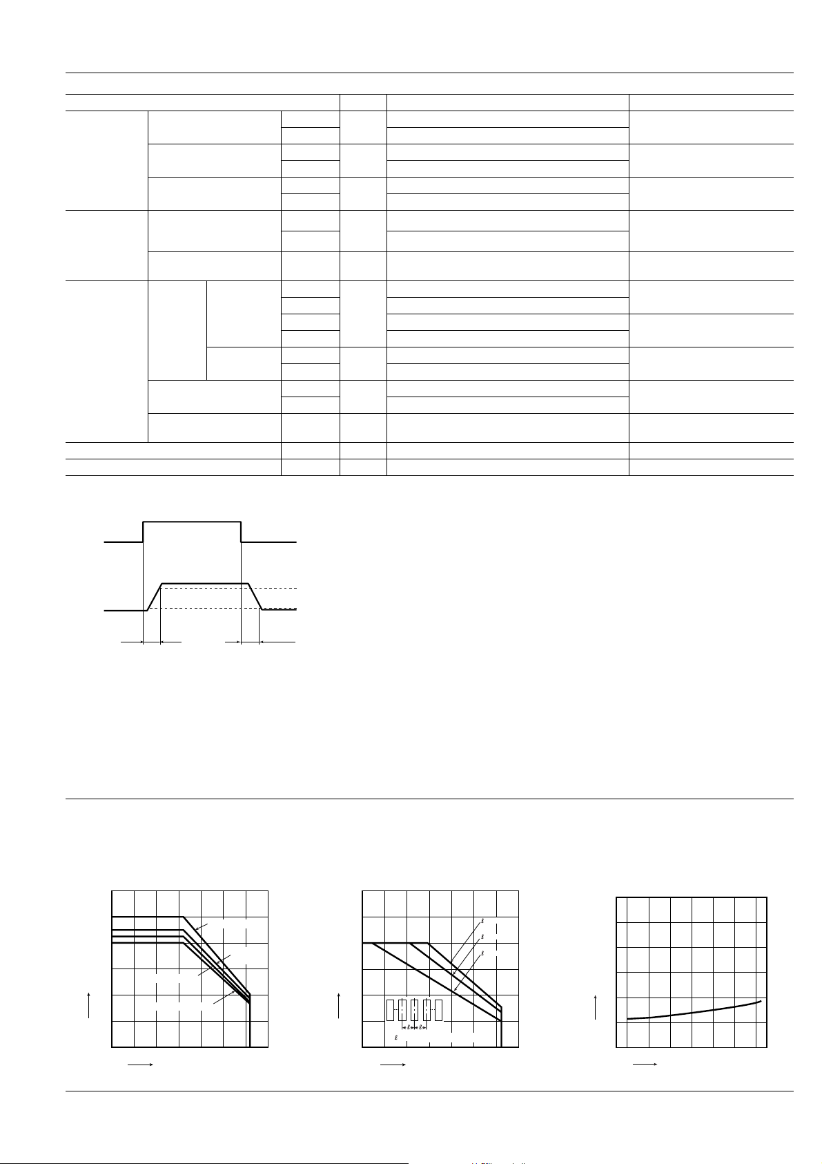
1. Load current vs. ambient temperature characteristics
Allowable ambient temperature: –40 ° C to +85 ° C
120
100
80
60
Load current, mA
40
20
3 circuit ON status
4 circuit ON status
0
–40 8085
0–20 20 40 60 100
Ambient temperature, °C
–40 ° F to +185 ° F
1 circuit ON status
2 circuit
ON status
90%
For Dimensions, see Page 29.
For Schematic and Wiring Diagrams, see Page 34.
For Cautions for Use, see Page 36.
2. Load current in adjacent mounting vs. ambient temperature
Condition: 4 circuits ON status
120
100
80
60
Load current, mA
40
20
0
–40 8085
=Adjacent mounting pitch
0–20 20 40 60 100
Ambient temperature, °C
=20mm
=10mm
=5mm
3. On resistance vs. ambient temperature characteristics
Measured portion: between terminals 6 and 7, 8 and
9, 10 and 11, 12 and 13; LED current: 5 mA;
Continuous load current: 80 mA (DC)
120
100
80
60
On resistance, Ω
40
20
0
–40
0–20 20 40 60
Ambient temperature, °C
80 85
61
 Loading...