

NAIS APE3014H, APE30148, APE30124, APE30118, APE30112 Datasheet
...
VDE
Pending
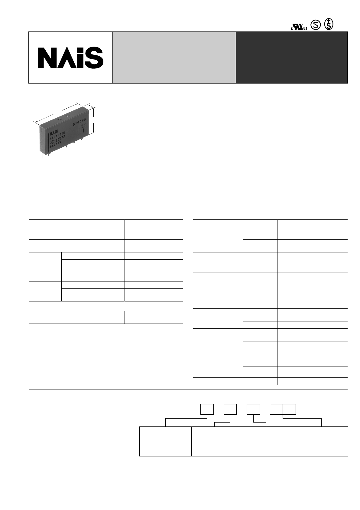
THE SLIM POWER RELAY
FEATURES
28
1.102
.197
15
.591
5
• Slim size
28 mm (L) × 5 mm (W) × 15 mm (H)
1.102 inch (L) × .197 inch (W) × .591 inch
(H)
permits high density mounting
• Wide switching capacity:
100 mA/12 V DC-6A/250 V AC
• High sensitivity: 170mW
• High breakdown (4,000 V) and surge
(6,000 V) voltage between contacts
and coil
• Clearance/creepage distance: 8/8 mm
• 1 Form A/1 Form C contact.
SPECIFICATIONS
Contacts
Arrangement 1 Form A, 1 Form C
Contact material Silver alloy
Initial contact resistance, max.
(By voltage drop 6 V DC 1 A)
100 m Ω
Nominal switching capacity 6 A 250 V AC
Rating (resistive)
Maximum switching power 1,500 VA
Maximum switching voltage 400 V AC/300 V DC
Max. switching current 6 A (AC)
Expected life
(min.operations)
Mechanical (at 180 cpm) 5 × 10
Electrical (at 6 cpm)
(at rated load)
Coil (at 25 ° C 77 ° F, 50% R.H.)
Nominal operating power
Remarks
* Specifications will vary with foreign standards certification ratings.
1
*
Measurement at same location as "Intial breakdown voltage" section
2
Detection current: 10mA
*
3
*
Wave is standard shock voltage of ± 1.2 × 50 µ s according to JEC-212-1981
4
*
Excluding contact bounce time
5
Half-wave pulse of sine wave: 50ms; detection time: 10 µ s
*
6
*
Half-wave pulse of sine wave: 11ms
7
*
Detection time: 10 µ s
8
Refer to 5. Conditions for operation, transport and storage mentioned in
*
AMBIENT ENVIRONMENT (Page 61).
170 mW (4.5 to 24 V DC)
217 mW (48 V DC)
Au-plated
silver alloy
6
N.O.: 5 × 10
N.C.: 3 × 10
30 m Ω
4
4
PE-RELAYS
Insulation complying to following standards:
EN 60255 General specification for electrical relays
EN 60335 For use in house-hold appliances
EN 60730 For use in temperature sensing appliances
EN 60950 For use in electrical business equipment
EN 60065 For use in entertainment electronics
(radio, HiFi-sets)
EN 50178 For use in industrial range
Characteristics
Initial insulation resistance*
Initial breakdown
2
voltage*
Surge voltage between contacts and
3
coil*
Operate time*
4
(at nominal voltage) Max. 8 ms (approx. 5 ms)
Release time (without diode)*
(at nominal voltage)
Temperature rise
Shock resistance
Vibration resistance
Conditions for operation,
transport and storage*
8
(Not freezing and condensing at low temperature)
Unit weight Approx. 4 g .14 oz
1
Between open
contacts
Between contacts and coil
Min. 1,000 M Ω at 500 V DC
1,000 Vrms
4,000 Vrms
Min. 6,000 V (Initial)
4
Max. 4 ms (approx. 2.5 ms)
Max. 30 ° C with nominal coil
voltage across
coil and at nominal switching
capacity
1 Form C: Min. 49 m/s
Functional*
Destructive*
Functional*
Destructive
Ambient
temp.
5
1 Form A: Min. 98 m/s
6
Min. 980 m/s
7
at double amplitude of 1.0 mm/6 G
2
{100 G}
10 to 55 Hz
10 to 55 Hz
at double amplitude of 1.5 mm/9 G
–40 ° C to +85 ° C
–40 ° F to +185 ° F
Humidity 5 to 85%R.H.
2
{5 G}
2
{10 G}
TYPICAL APPLICATIONS
• Interface relays for programmable controllers
• Output relays for measuring equipment,
timers, counters and temperature controllers
• Industrial equipment, office equipment
• House-hold appliances for Europe
ORDERING INFORMATION
Ex.
APE 0
Contact arrangement Contact type
1: 1 Form A
0: Single contact
3: 1 Form C
(Notes) 1. Standard packing: Tube: 20 pcs.; Case: 1,000 pcs.
2. 5 V, 60 V type is also available.
3. 1 Form B is also available.
Contact material
0: Silver alloy
1: Au-plated silver alloy
Coil voltage (DC)
4H: 4.5 V
06: 6 V
12: 12 V
18: 18 V
24: 24 V
48: 48 V
211
NOCOM
Coil
NOCOM
Coil
NC
Ω ( ±
PE
TYPES AND COIL DATA (at 20 ° C 68 ° F)
Pick-up
voltage,
(Initial)
V DC (max.)
Part No.
APE1004H
Contact
arrangement
Nominal
voltage,
V DC
4.5 2.97 0.225 38
APE10006 6 3.96 0.3 28 212 7.2
APE10012 12 7.92 0.6 14 847 14.4
APE10018 18 11.88 0.9 9 1,906 21.6
1 Form A
(without Au-
plated)
APE10024 24 15.84 1.2 7 3,388 28.8
APE10048 48 31.68 2.4 5 217 10,618 57.6
APE1014H
4.5 2.97 0.225 38
APE10106 6 3.96 0.3 28 212 7.2
APE10112 12 7.92 0.6 14 847 14.4
APE10118 18 11.88 0.9 9 1,906 21.6
1 Form A
(with Au-plated)
APE10124 24 15.84 1.2 7 3,388 28.8
APE10148 48 31.68 2.4 5 217 10,618 57.6
APE3004H
4.5 2.97 0.225 38
APE30006 6 3.96 0.3 28 212 7.2
APE30012 12 7.92 0.6 14 847 14.4
APE30018 18 11.88 0.9 9 1,906 21.6
1 Form C
(without Au-
plated)
APE30024 24 15.84 1.2 7 3,388 28.8
APE30048 48 31.68 2.4 5 217 10,618 57.6
APE3014H
4.5 2.97 0.225 38
APE30106 6 3.96 0.3 28 212 7.2
APE30112 12 7.92 0.6 14 847 14.4
APE30118 18 11.88 0.9 9 1,906 21.6
1 Form C
(with Au-plated)
APE30124 24 15.84 1.2 7 3,388 28.8
APE30148 48 31.68 2.4 5 217 10,618 57.6
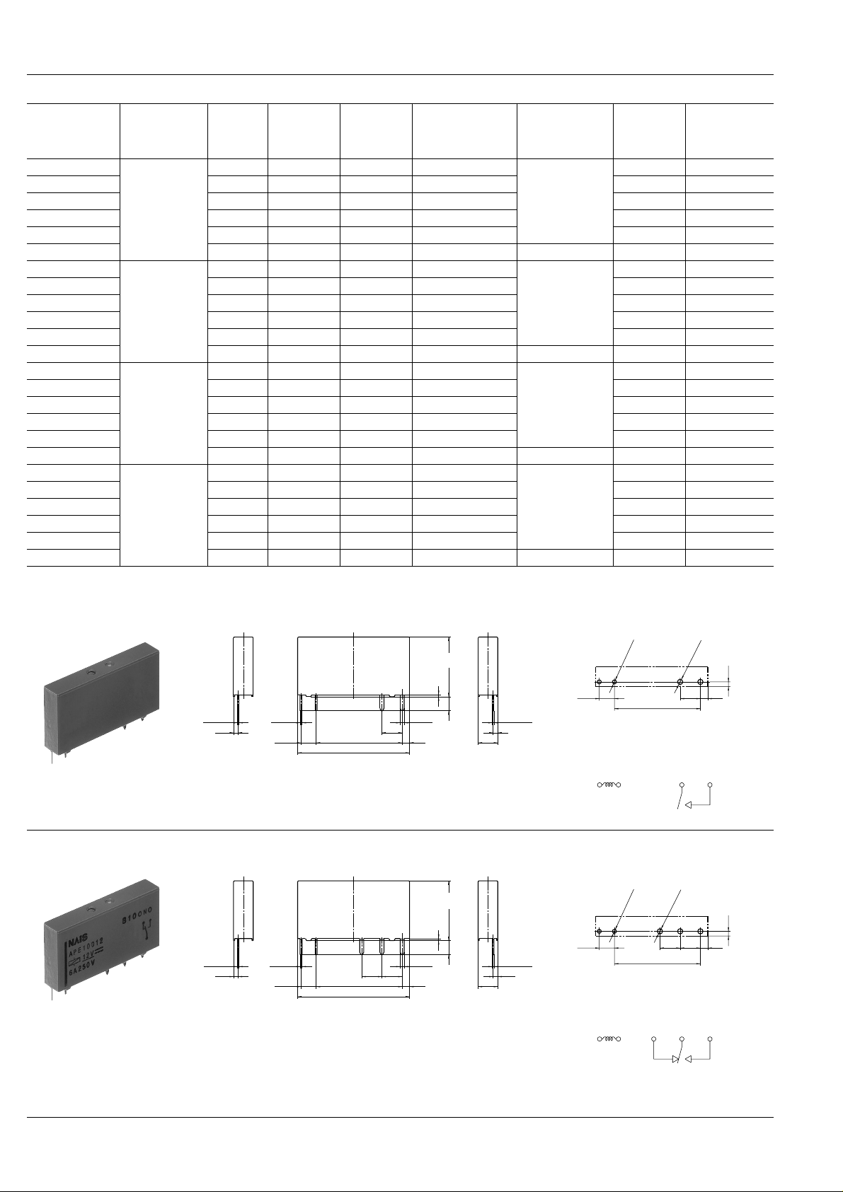
DIMENSIONS
1. 1 Form A type
Drop-out
voltage,
(Initial)
V DC (min.)
Nominal operating
current,
mA ( ± 10%)
Nominal
operating power,
mW
170
170
170
170
PC board pattern (Bottom view)
Coil
resistance,
10%)
119 5.4
119 5.4
119 5.4
119 5.4
Max. allowable
voltage,
V DC
mm inch
2. 1 Form C type
0.3
.012
0.3
.012
+0.2
–0.1
+.008
–.004
1.2
.047
+0.2
–0.1
+.008
–.004
1.2
.047
2-0.5
2-.020
3.78
.149
2-0.5
2-.020
3.78
.149
21.42
.843
28.0max.
1.102max.
21.42
.843
28.0max.
1.102max.
15.0max.
.591max.
0.5
.020
3.5
.138
2-1.0
2-.039
5.04
.198
1.9
.075
5.0max.
.197max.
General tolerance: ± 0.3 ± .012
15.0max.
.591max.
0.5
.020
3.5
.138
3-1.0
3-.039
5.04
5.04
.198
.198
1.9
.075
5.0max.
.197max.
General tolerance: ± 0.3 ± .012
0.4
.016
0.4
.016
1.2
.047
1.2
.047
1.2
.047
2-1.3 dia.
5.04
.198
2-.051 dia.
1.9
.075
2-1.0 dia.
2-.039 dia.
3.78
+0.2
–0.1
+.008
–.004
.149
21.42
.843
Tolerance: ± 0.1 ± .004
Schematic (Bottom view)
PC board pattern (Bottom view)
1.2
5.04
.198
1.9
.075
.047
2-1.0 dia.
2-.039 dia.
3-1.3 dia.
3-.051 dia.
21.42
.843
5.04
.198
+0.2
–0.1
+.008
–.004
3.78
.149
Tolerance: ± 0.1 ± .004
Schematic (Bottom view)
212
 Loading...