

NAIS ALE75F48, ALE75F24, ALE75F18, ALE75F12, ALE75F09 Datasheet
...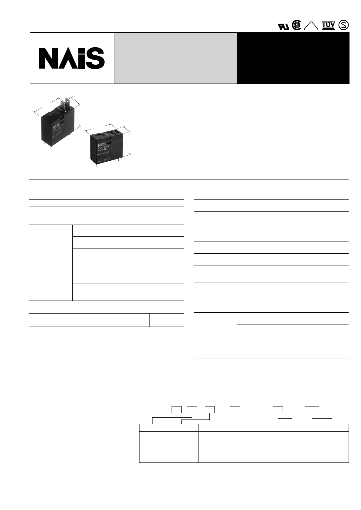
16A Power Relay For
Micro wave oven
VDE
LE RELA YS
LE
FEATURES
1. Ideal for magnetron and heater
loads
2. Excellent heat resistance
• This satisfies UL coil insulation class B/
12.4
.488
class F available
28.6
1.126
12.4
.488
24.9
.980
28.6
1.126
3. High insulation resistance
24.9
• Creepage distance and clearances be-
.980
tween contact and coil: Min. 8 mm .315
inch
• Surge withstand voltage: Min. 10,000V
mm inch
SPECIFICATIONS
Contact
Arrangement 1 Form A
Initial contact resistance, max.
(By voltage drop 6 V DC 1 A)
Contact material Silver alloy
Nominal switching capacity
Max. switching
Rating
(resistive load)
power
Max. switching
voltage
Max. switching
current
Mechanical
Expected life
(min. operations)
(at 180 cpm)
Electrical
(at 20 cpm)
(Resistive load)
Coil
Type Standard High sensitive
Nominal operating power 400 mW 200 mW
Remarks
∗
Specifications will vary with foreign standards certification ratings.
1
*
Measurement at same location as “Initial breakdown voltage” section.
2
*
Detection current: 10mA
3
*
Wave is standard shock voltage of ±1.2 × 50µs according to JEC-212-1981
4
*
Excluding contact bounce time.
5
*
Half-wave pulse of sine wave: 11 ms; detection time: 10 µs
6
*
Half-wave pulse of sine wave: 6 ms
7
*
Detection time: 10 µs
8
*
Refer to 5. Conditions for operation, transport and storage mentioned in
AMBIENT ENVIRONMENT (Page 24).
100 m
Ω
16 A 277 V AC
4,432 V A
277 V AC
16 A
6
2 × 10
5
10
4. Low operating power
• Nominal operating power: 400mW/
200mW (High sensitive type)
5. A wide variety of types
• Product line consists of 4 types with different shapes and pins
6. Conforms to the various safety
standards:
• UL/CSA, TÜV, VDE approved and
SEMKO available
Characteristics
Max. operating speed
(at rated load)
Initial insulation resistance*
1
Min. 1,000 MΩ (at 500 V DC)
Between open
Initial breakdown
2
voltage*
contacts
Between con-
tacts and coil
Initial surge voltage between contact
and coil*
Operate time*
3
4
(at nominal voltage) (at 20°C 68°F)
Release time (with diode)*
4
(at nominal voltage) (at 20°C 68°F)
Temperature rise (at nominal voltage)
(resistance method, contact current
16 A, 20°C 68°F)
Shock resistance
Vibration
resistance
Conditions for operation,
transport and storage
(Not freezing and condensing at low temperature)
Functional*
Destructive*
Functional*
Destructive
Ambient temp.
8
*
Humidity 5 to 85% R.H.
5
6
7
at double amplitude of 1.5mm
at double amplitude of 1.5mm
Unit weight Approx. 17 g .60 oz
20 cpm
1,000 Vrms for 1 min.
4,000 Vrms for 1 min.
Min. 10,000 V
Max. 20ms
Max. 20ms
Max. 25ms
(200 mW type)
Max. 55°C
Max. 45°C
(200 mW type)
Min. 200 m/s2{20 G}
Min. 1,000 m/s2{100 G}
10 to 55Hz
10 to 55Hz
–40°C to +85°C
–40°F to +185°F
TYPICAL APPLICATIONS
• Microwave ovens
• Refrigerators
• OA equipment
ORDERING INFORMATION
LE
Product name
LE
Contact arrangement
1: 1 Form A
7: 1 Form A
(200 mW)
2: TMP type/PCB side three terminals
(includes one dummy terminal)
3: TMP type/PCB side three terminals
4: TMP type/PCB side four terminals
5: PCB type (No tab terminals)
UL/CSA, TÜV, VDE approved type is standard.
Note: Standard packing; Carton: 100 pcs. Case 500 pcs.
2B121AEx.
Terminal shape
Coil insulation class
B: Class B insulation
F: Class F insulation
Coil voltage, V DC
05: 5
18: 18
06: 6
24: 24
09: 9
48: 48
12: 12
43
LE
TYPES
1. Standard type
Contact
arrangement
1 Form A
❍
: Input the following letter. Class B: B, Class F: F
2. High sensitive type
Contact
arrangement
1 Form A
(High sensitivity:
200mW)
❍
: Input the following letter. Class B: B, Class F: F
Coil voltage,
V DC
5 ALE12❍05 ALE13❍05 ALE14❍05 ALE15❍05
6 ALE12❍06 ALE13❍06 ALE14❍06 ALE15❍06
9 ALE12❍09 ALE13❍09 ALE14❍09 ALE15❍09
12 ALE12❍12 ALE13❍12 ALE14❍12 ALE15❍12
18 ALE12❍18 ALE13❍18 ALE14❍18 ALE15❍18
24 ALE12❍24 ALE13❍24 ALE14❍24 ALE15❍24
48 ALE12❍48 ALE13❍48 ALE14❍48 ALE15❍48
Coil voltage,
V DC
5 ALE72❍05 ALE73❍05 ALE74❍05 ALE75❍05
6 ALE72❍06 ALE73❍06 ALE74❍06 ALE75❍06
9 ALE72❍09 ALE73❍09 ALE74❍09 ALE75❍09
12 ALE72❍12 ALE73❍12 ALE74❍12 ALE75❍12
18 ALE72❍18 ALE73❍18 ALE74❍18 ALE75❍18
24 ALE72❍24 ALE73❍24 ALE74❍24 ALE75❍24
48 ALE72❍48 ALE73❍48 ALE74❍48 ALE75❍48
TMP type/PCB side
three terminals
(includes one dummy
terminal)
Part No. Part No. Part No. Part No.
TMP type/PCB side
three terminals
(includes one dummy
terminal)
Part No. Part No. Part No. Part No.
TMP type/PCB side
three terminals
TMP type/PCB side
three terminals
TMP type/PCB side
four terminals
TMP type/PCB side
four terminals
PCB type
(No tab terminals)
PCB type
(No tab terminals)
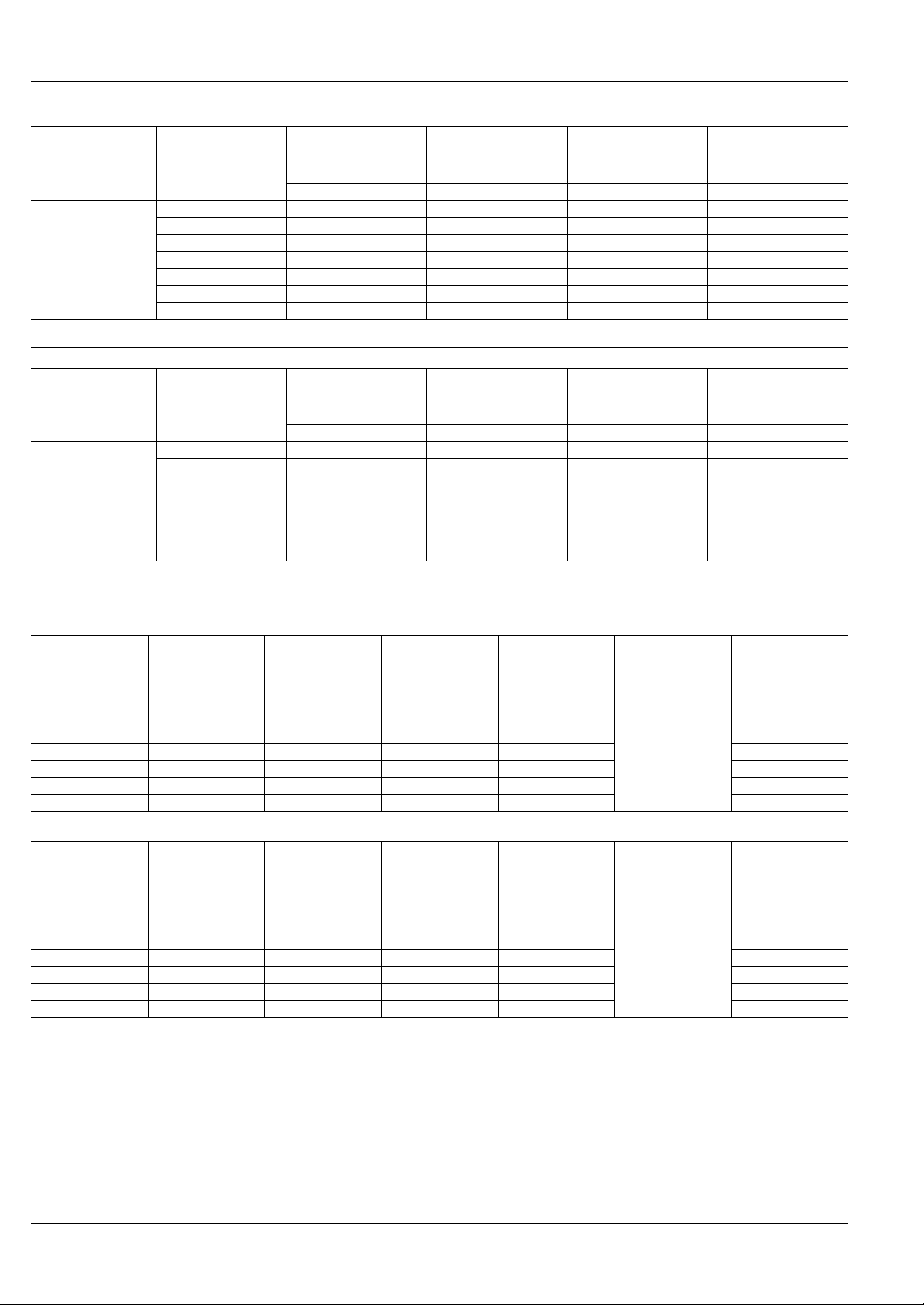
COIL DATA (at 20°C 68°F)
1. Standard type
Nominal voltage,
V DC
5 3.75 0.25 63 80
6 4.5 0.3 90 66.7 8.7
9 6.75 0.45 203 44.4 13.05
12 9 0.6 360 33.3 17.4
18 13.5 0.9 810 22.2 26.1
24 18 1.2 1,440 16.7 34.8
48 36 2.4 5,760 8.3 69.6
2. High sensitive type
Nominal voltage,
V DC
5 3.75 0.25 125 40
6 4.5 0.3 180 33.3 8.7
9 6.75 0.45 405 22.2 13.05
12 9 0.6 720 16.7 17.4
18 13.5 0.9 1,620 11.1 26.1
24 18 1.2 2,880 8.3 34.8
48 36 2.4 11,520 4.2 69.6
Pick-up voltage,
V DC (max.)
(at 20°C 68°F)
Pick-up voltage,
V DC (max.)
(at 20°C 68°F)
Drop-out voltage,
Drop-out voltage,
V DC (min.)
(at 20°C 68°F)
V DC (min.)
(at 20°C 68°F)
Coil resistance,
Ω (±
10%)
(at 20°C 68°F)
Coil resistance,
Ω (±
10%)
(at 20°C 68°F)
Nominal operating
current, mA
(±10%)
(at 20°C 68°F)
Nominal operating
current, mA
(±10%)
(at 20°C 68°F)
Nominal operating
power, mW
(at 20°C 68°F)
400
Nominal operating
power, mW
(at 20°C 68°F)
200
Maximum
allowable voltage,
V DC
(at 20°C 68°F)
7.25
Maximum
allowable voltage,
V DC
(at 20°C 68°F)
7.25
44
 Loading...