

NAIS AGQ210S4HZ, AGQ210S4H, AGQ210S24, AGQ210S1HZ, AGQ210S1HX Datasheet
...
GQ
129
GQ-RELAYS
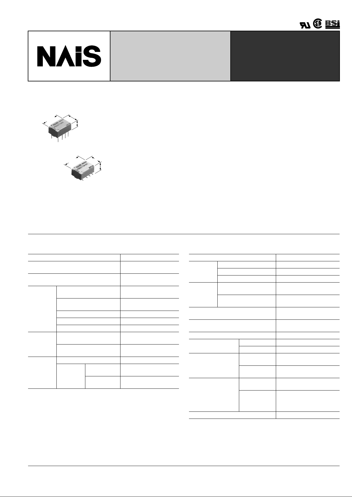
ULTRA-SMALL P ACKAGE
FLAT POLARIZED RELAY
7.20±0.3
.283±.012
10.60±0.3
.417±.012
5.20±0.2
.205±.008
10.60±0.3
.417±.012
Max.5.40
.213
7.20±0.3
.283±.012
mm inch
FEATURES
• Compact flat body saves space
With a small footprint of 10.6 mm (L) × 7.2
mm (W) .417 inch (L) × .283 inch (W) for
space savings, it also has a very short
height of 5.2 mm .205 inch. (Standard PC
board type.)
• Outstanding surge resistance.
Surge withstand between open contacts:
1,500 V 10 × 160 µ s (FCC part 68)
Surge withstand between contacts and
coil: 2,500 V 2 × 10 µ s (Bellcore)
• The use of twin cr ossbar contacts ensures high contact reliability.
AgPd contact is used because of its good
sulfide resistance. Adopting low-gas
molding material. Coil assembly molding
technology which avoids generating volatile gas from coil.
• Increased packaging density
Due to highly efficient magnetic circuit design, leakage flux is reduced and changes
in electrical characteristics from components being mounted close-together are
minimized. This all means a packaging
density higher than ever before.
• Nominal operating power: 140 mW
• Outstanding vibration and shock resistance.
Functional shock resistance:
750 m/s
2
{75G}
Destructive shock resistance:
1,000 m/s
2
{100G}
Functional vibration resistance:
10 to 55 Hz (at double amplitude of 3.3
mm .130 inch)
Destructive vibration resistance:
10 to 55 Hz (at double amplitude of 5 mm
.197 inch)
SPECIFICATIONS
Contact
Remarks:
* Specifications will vary with foreign standards certification ratings.
*
1
Measurement at same location as "Initial breakdown voltage" section.
*
2
Detection current: 10mA.
*
3
Nominal voltage applied to the coil, excluding contact bounce time.
*
4
By resistive method, nominal voltage applied to the coil; contact carrying current:
1 A.
*
5
Half-wave pulse of sine wave: 6 ms;detection time: 10 µ s.
*
6
Half-wave pulse of sine wave: 6 ms.
*
7
Detection time: 10 µ s .
*
8
Refer to 5. Conditions for operation, transport and storage mentioned in
AMBIENT ENVIRONMENT (Page 61)
Characteristics
Notes:
❇
1 This value can change due to the switching frequency , environmental conditions ,
and desired reliability level, therefore it is recommended to check this with the
actual load.
❇
2 The upper limit for the ambient temperature is the maximum temperature that
can satisfy the coil temperature rise. Under the packing condition, allowable
temperature range is from –40 to +70 ° C –40 ° to +158 ° F.
Arrangement 2 Form C
Initial contact resistance, max.
(By voltage drop 6 V DC 1A )
100 m Ω
Contact material
Stationary: AgPd+Au clad
Movable: AgPd
Rating
Nominal switching capacity
(resistive load)
1 A 30 V DC
0.3 A 125 V AC
Max. switching power
(resistive load)
30 W, 37.5 V A
Max. switching voltage 110 V DC, 125 V AC
Max. switching current 1 A
Min. switching capacity ❇ 1 10 µ A 10 mV DC
Nominal
operating
power
Single side stable
140mW (1.5 to 12 V DC)
230mW (24 V DC)
1 coil latching
100mW (1.5 to 12 V DC)
120mW (24 V DC)
Expected
life (min.
operations)
Mechanical (at 180 cpm) 5 × 10
7
Electrical
(at 20 cpm)
1 A 30 V DC
resistive
10
5
0.3 A 125 V AC
resistive
10
5
Initial insulation resistance*
1
Min. 1,000M Ω (at 500V DC)
Initial
breakdown
voltage*
2
Between open contacts 750 Vrms for 1min.
Between contact sets 1,000 Vrms for 1min.
Between contacts and coil 1,500 Vrms for 1min.
Initial surge
voltage
Between open contacts
(10 × 160 µ s)
1,500 V(FCC Part 68)
Between contacts and coil
(2 × 10 µ s)
2,500 V(Bellcore)
Operate time [Set time]*
3
(at 20 ° C)
Max. 4 ms (Approx. 2 ms)
[Max. 4 ms (Approx. 2 ms)]
Release time (without diode)
[Reset time]*
3
(at 20 ° C)
Max. 4 ms (Approx. 1 ms)
[Max. 4 ms (Approx. 2 ms)]
Temperature rise*
4
(at 20 ° C) Max. 50 ° C
Shock resistance
Functional*
5
Min. 750 m/s
2
{75G]
Destructive*
6
Min. 1,000 m/s
2
{100G]
Vibration resistance
Functional*
7
10 to 55 Hz at double
amplitude of 3.3 mm
Destructive
10 to 55 Hz at double
amplitude of 5 mm
Conditions for operation, transport and
storage*
8
(Not freezing and condensing at low temperature)
Ambient
temperature ❇ 2
–40 ° C to 85 ° C
–40 ° F to 185 ° F
Humidity 5 to 85% R.H.
Unit weight Approx. 1 g .035 oz
TESTING
GQ
130
TYPICAL APPLICATIONS
• Telephone exchange, transmission
equipment
• Communications devices
• Measurement devices
• Home appliances, and audio/visual
equipment
• Handheld and portable products
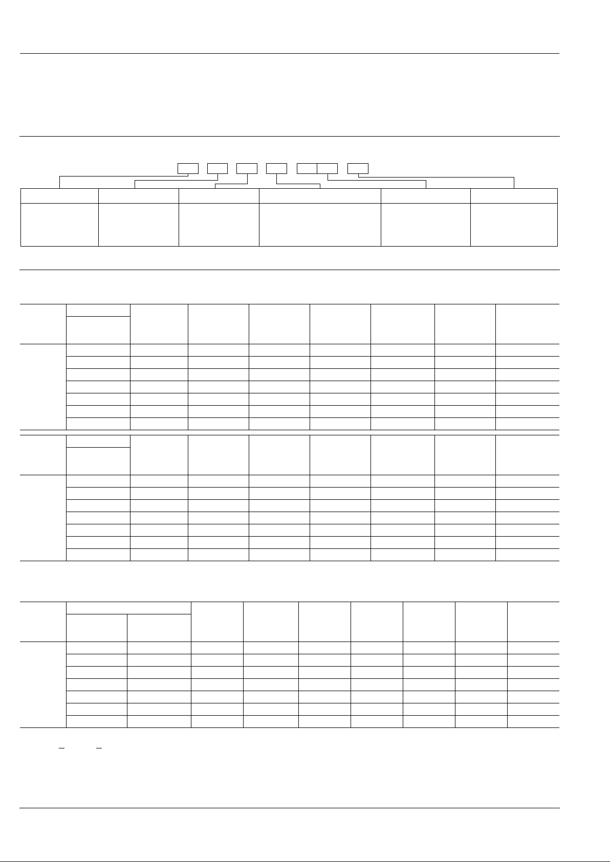
ORDERING INFORMATION
200A Z1HEx. AGQ
Contact arrangement
Terminal shapeOperating function Packing style
Coil voltage (DC)
Nil: Standard PC board terminal
A: Surface-mount terminal A type
S: Surface-mount terminal S type
2: 2 Form C 0: Single side stable
1: 1 coil latching
Type of operation
0: Standard type
(B.B.M.)
Nil: Tube packing
Z:
Tape and reel packing
(piked from 5/6/7/8
pin side)
1H: 1.5V
03 : 3V
4H: 4.5V
06 : 6V
09 : 9V
12 : 12V
24 : 24V
Note: Tape and reel packing symbol “-Z” is not marked on the relay. “X” type tape and reel packing (picked from 1/2/3/4-pin side) is also available. Suffix “X” instead of “Z”.
TYPES AND COIL DATA (at 20 ° C 68 ° F)
(1) Standard PC board terminal
1) Standard packing: 50 pcs. in an inner package (tube); 1,000 pcs. in an outer package
2) Specified value of pick-up, drop-out, set and reset voltage is with the condition of square wave coil pulse.
(2) Surface-mount terminal
❍
: For each surface-mounted terminal variation, input the following letter.
A type: A
, S type: S
1) Standard packing: 50 pcs.(tube), 900pcs. (tape and reel)in an inner package; 1,000 pcs.(tube), 1,800pcs. (tape and reel)in an outer package
2) Specified value of pick-up, drop-out, set and reset voltage is with the condition of square wave coil pulse.
Operating
Function
Part No.
Coil Rating,
V DC
Pick-up volt-
age, V DC
(max.)
(initial)
Drop-out
voltage,
V DC (min.)
(initial)
Nominal
operating
current,
mA ( ± 10%)
Coil resistance,
Ω ( ±
10%)
Nominal
operating
power, mW
Max. allowable
voltage,
V DC
Standard PC
board terminal
Single side
stable
AGQ2001H 1.5 1.13 0.15 93.8 16 140 2.25
AGQ20003 3 2.25 0.3 46.7 64.2 140 4.5
AGQ2004H 4.5 3.38 0.45 31 145 140 6.75
AGQ20006 6 4.5 0.6 23.3 257 140 9
AGQ20009 9 6.75 0.9 15.5 579 140 13.5
AGQ20012 12 9 1.2 11.7 1,028 140 18
AGQ20024 24 18 2.4 9.6 2,504 230 28.8
Operating
Function
Part No.
Coil Rating,
V DC
Set voltage,
V DC (max.)
(initial)
Reset voltage,
V DC (max.)
(initial)
Nominal
operating
current,
mA ( ± 10%)
Coil resistance,
Ω ( ±
10%)
Nominal
operating
power, mW
Max. allowable
voltage,
V DC
Standard PC
board terminal
1 coil
latching
AGQ2101H 1.5 1.13 1.13 66.7 22.5 100 2.25
AGQ21003 3 2.25 2.25 33.3 90 100 4.5
AGQ2104H 4.5 3.38 3.38 22.2 202.5 100 6.75
AGQ21006 6 4.5 4.5 16.7 360 100 9
AGQ21009 9 6.75 6.75 11.1 810 100 13.5
AGQ21012 12 9 9 8.3 1,440 100 18
AGQ21024 24 18 18 5.0 4,800 120 36
Operating
Function
Part No.
Coil Rating,
V DC
Pick-up
voltage,
V DC (max.)
(initial)
Drop-out
voltage,
V DC (min.)
(initial)
Nominal
operating
current,
mA ( ± 10%)
Coil
resistance,
Ω ( ±
10%)
Nominal
operating
power,
mW
Max.
allowable
voltage,
V DC
Tube packing
Tape and reel
packing
Single side
stable
AGQ200 ❍ 1H AGQ200 ❍ 1HZ 1.5 1.13 0.15 93.8 16 140 2.25
AGQ200 ❍ 03 AGQ200 ❍ 03Z 3 2.25 0.3 46.7 64.2 140 4.5
AGQ200 ❍ 4H AGQ200 ❍ 4HZ 4.5 3.38 0.45 31 145 140 6.75
AGQ200 ❍ 06 AGQ200 ❍ 06Z 6 4.5 0.6 23.3 257 140 9
AGQ200 ❍ 09 AGQ200 ❍ 09Z 9 6.75 0.9 15.5 579 140 13.5
AGQ200 ❍ 12 AGQ200 ❍ 12Z 12 9 1.2 11.7 1,028 140 18
AGQ200 ❍ 24 AGQ200 ❍ 24Z 24 18 2.4 9.6 2,504 230 28.8
 Loading...