

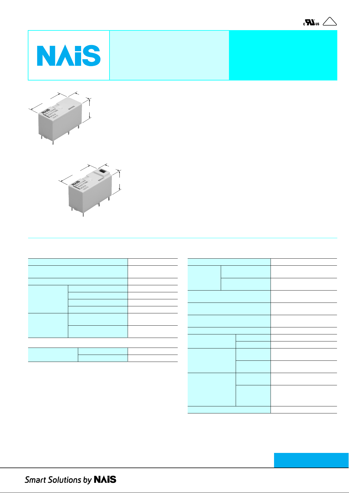
16A, COMPACT AND
HIGH INSULATION
POWER LATCHING RELAY
VDE
pendingpending
DJ-RELAYS
FEATURES
1. Latching operation
Latching via a polarized magnetic circuit
structure allows remote operation and
29.0
1.142
13.0
.512
16.0
.630
lower energy consumption
2. Compact with high capacity
16A contact rating in a compact 29 x 13 x
16.5 mm (L x W x H) size.
3. Low power consumption
Without test button
1 coil latching: 150mW
2 coil latching: 250mW
29.0
1.142
13.0
.512
16.0
.630
4. High insulation
Both clearance and creepage distance
between coil and contact are at 8 mm min.
5. With operation verification function
A test button (manual lever) type to
facilitate circuit checks is also available.
With test button
SPECIFICATIONS
Contact
Arrangement 1 Form A, 1 Form C
Initial contact resistance, max.
(By voltage drop 6 V DC 1 A)
Contact material Silver alloy
Nominal switching capacity 16 A 250V AC
Rating
(resistive load)
Expected life
(min. operations)
Max. switching power 4,000 V A
Max. switching voltage 250V AC
Max. switching current 16 A
Mechanical
(at 180 cpm)
Electrical (Resistive load)*
(at 20 cpm)
1
Coil
Nominal operating
power
Remarks
* Specifications will vary with foreign standards certification ratings.
*1With breathing holes open
2
Measurement at same location as “Initial breakdown voltage” section.
*
*3Detection current: 10mA
4
Wave is standard shock voltage of ±1.2 × 50µs according to JEC-212-1981
*
*5Excluding contact bounce time.
6
By resistive method, max. switching current
*
*7Half-wave pulse of sine wave: 11 ms; detection time: 10 µs
*8Half-wave pulse of sine wave: 6 ms
9
Detection time: 10 µs
*
*10Refer to 5. Usage, transport and storage conditions mentioned in NOTES
1 coil latching 150mW
2 coil latching 250mW
100 m
Ω
6
5×10
105 (at 16A 250V AC)
TYPICAL APPLICATIONS
• Network for household appliances
(Motor control, Light control)
• Time switches
Characteristics
Initial insulation resistance*
Initial
breakdown
voltage*
Surge voltage between contact and
4
coil*
Set time*
(at nominal voltage)
Reset time*
(at nominal voltage)
Temperature rise (at 70°C)*
Shock
resistance
Vibration
resistance
Conditions for
operation, transport
and storage*
(Not freezing and
condensing at low
temperature)
Unit weight Approx. 14 g .49 oz
Between open
contacts
Between contacts and
3
coil
5
5
10
2
6
Functional*
Destructive*
Functional*
Destructive
Ambient
temperature
Humidity 5 to 85% R.H.
Min. 1,000 MΩ (at 500 V DC)
1,000 Vrms for 1 min.
4,000 Vrms for 1 min.
Min. 10,000 V (initial)
Approx. 10ms
Approx. 10ms
Max. 55°C
7
8
9
Min. 200 m/s2 {20 G}
Min. 1,000 m/s2 {100 G}
10 to 55Hz
at double amplitude of 2.0mm
10 to 55Hz
at double amplitude of 3.0mm
–40°C to +70°C
–40°F to +158°F
http://www.naisrelay.com/
DJ RELAY
ASCT1B258E ’03.1
New
1
DJ
ORDERING INFORMATION
Ex. ADJ
Contact arrangement
1: 1 Form C
2: 1 Form A
Note: Standard packing: Carton: 100 pcs, Case: 500 pcs
Operating function and protective construction Auxiliary function Coil voltage (DC)
1: 1 coil latching, Flux-resistant type
2: 1 coil latching, Sealed type
3: 2 coil latching, Flux-resistant type
4: 2 coil latching, Sealed type
TYPES
1. Without test button
1) Flux-resistant type
Contact arrangement Coil voltage, V DC
5 ADJ21005 ADJ23005
6 ADJ21006 ADJ23006
1 Form A
1 Form C
2) Sealed type
Contact arrangement Coil voltage, V DC
1 Form A
1 Form C
2. With test button
Flux-resistant type
Contact arrangement Coil voltage, V DC
1 Form A
1 Form C
12 ADJ21012 ADJ23012
24 ADJ21024 ADJ23024
48 ADJ21048 ADJ23048
5 ADJ11005 ADJ13005
6 ADJ11006 ADJ13006
12 ADJ11012 ADJ13012
24 ADJ11024 ADJ13024
48 ADJ11048 ADJ13048
5 ADJ22005 ADJ24005
6 ADJ22006 ADJ24006
12 ADJ22012 ADJ24012
24 ADJ22024 ADJ24024
48 ADJ22048 ADJ24048
5 ADJ12005 ADJ14005
6 ADJ12006 ADJ14006
12 ADJ12012 ADJ14012
24 ADJ12024 ADJ14024
48 ADJ12048 ADJ14048
5 ADJ21105 ADJ23105
6 ADJ21106 ADJ23106
12 ADJ21112 ADJ23112
24 ADJ21124 ADJ23124
48 ADJ21148 ADJ23148
5 ADJ11105 ADJ13105
6 ADJ11106 ADJ13106
12 ADJ11112 ADJ13112
24 ADJ11124 ADJ13124
48 ADJ11148 ADJ13148
0: Without test button
1: With test button
1 coil latching type 2 coil latching type
Part No. Part No.
1 coil latching type 2 coil latching type
Part No. Part No.
1 coil latching type 2 coil latching type
Part No. Part No.
05: 5 V
06: 6 V
12: 12 V
24: 24 V
48: 48 V
2

COIL DATA (at 20°C 68°F)
10.16
.400
3.50
.138
13.0
.512
42−1
+8
−9
−8
+142
42−1
+8
−9
−8
+142
• 1 coil latching type
Nominal voltage,
V DC
5 3.5 3.5 167
6 4.2 4.2 240 7.8
12 8.4 8.4 960 15.6
24 16.8 16.8 3,840 31.2
48 33.6 33.6 15,360 62.4
Set voltage,
max. V DC
(initial)
• 2 coil latching type
Nominal voltage,
V DC
5 3.5 3.5 100
6 4.2 4.2 144 7.8
12 8.4 8.4 576 15.6
24 16.8 16.8 2,304 31.2
48 33.6 33.6 9,216 62.4
Set voltage,
max. V DC
(initial)
DIMENSIONS
1. 1 Form A, without test button
16.0
.630
Reset voltage,
max. V DC
(initial)
Reset voltage,
max. V DC
(initial)
Coil resistance,
Ω (±
10%)
Coil resistance,
Ω (±
10%)
1 coil latching type 2 coil latching type
3.50
.138
Nominal operating
power,
mW
150
Nominal operating
power,
mW
250
PC board pattern (Bottom view)
1.50 dia.
.059 dia.
5.08
.200
5.08
.200
5.08
.200
15.24
.600
2 coil latching type only
DJ
Max. allowable
voltage,
V DC
6.5
Max. allowable
voltage,
V DC
6.5
mm inch
5.08
.200
Tolerance: ±0.1 ±.004
1.80
.071
2. 1 Form A, with test button
16.0
.630
1.80
.071
15.24
.600
15.24
.600
29.0
1.142
.248
29.0
1.142
6.3
10.16
.400
10.16
.400
10.16
.400
13.0
.512
General tolerance: ±0.3 ±.012
1 coil latching type 2 coil latching type
9.0
.354
18.2
.717
3.50
.138
10.16
.400
13.0
.512
3.50
.138
9.0
.354
10.16
.400
13.0
.512
Schematic (Bottom view)
1 coil latching type
(Reset condition)
2 coil latching type
(Reset condition)
PC board pattern (Bottom view)
1.50 dia.
.059 dia.
5.08
.200
5.08
.200
5.08
.200
15.24
.600
2 coil latching type only
Tolerance: ±0.1 ±.004
Schematic (Bottom view)
1 coil latching type
2 coil latching type
5.08
.200
General tolerance: ±0.3 ±.012
(Reset condition)
(Reset condition)
3

DJ
10.16
.400
3.50
.138
13.0
.512
2 coil latching type only
15.24
.600
1.50 dia.
.059 dia.
5.08
.200
5.08
.200
5.08
.200
5.08
.200
2 coil latching type only
15.24
.600
1.50 dia.
.059 dia.
5.08
.200
5.08
.200
5.08
.200
5.08
.200
3. 1 Form C, without test button
16.0
.630
1.80
.071
4. 1 Form C, with test button
15.24
.600
5.08
.200
29.0
1.142
.248
6.3
1 coil latching type 2 coil latching type
3.50
.138
10.16
5.08
.200
.400
13.0
.512
General tolerance: ±0.3 ±.012
1 coil latching type 2 coil latching type
9.0
.354
9.0
.354
PC board pattern (Bottom view)
Tolerance: ±0.1 ±.004
Schematic (Bottom view)
1 coil latching type
−1
+8
6
(Reset condition)
2 coil latching type
+1
42
−9
−8
(Reset condition)
PC board pattern (Bottom view)
mm inch
42
6
16.0
.630
1.80
.071
15.24
.600
5.08
.200
29.0
1.142
5.08
.200
18.2
.717
3.50
.138
10.16
.400
13.0
.512
General tolerance: ±0.3 ±.012
3.50
.138
10.16
.400
13.0
.512
Schematic (Bottom view)
1 coil latching type
−1
+8
42
6
(Reset condition)
Tolerance: ±0.1 ±.004
2 coil latching type
+1
−9
−8
42
6
(Reset condition)
4

REFERENCE DATA
1. Max. switching capacity 2. Temperature rise
100
AC resistive load
16
10
Contact current, A
100 100 1,000
Contact voltage, V
Sample: ADJ12024, 6 pcs.
Coil applied voltage: 0 %V, Contact current: 16 A, 20 A
Measured portion: Contact, Ambient temperature:
25°C 77°F, 85°C 185°F
40
35
30
25
20
15
Temperature rise, °C
10
5
0
010 25
51520
Contact current, A
+25°C
+85°C
3. Set and Reset time
Sample: ADJ12024, 10 pcs
30
25
20
15
10
Set and Reset time, ms
5
0
70 90 130
80 100 110 120
Coil applied voltage, %V
Max.
x
Min.
DJ
4. Ambient temperature characteristics
Sample: ADJ12024, 6pcs
Ambient temperature: –40 to +85°C –40 to 185°F
30
Set
Reset
20
10
Change rate
-40-60 -20 02040 60 80 100
to nominal V, %V
Ambient
temperature, °C
-10
-20
-30
NOTES
1. Coil operating power
Pure DC current should be applied to the
coil. The wav e form should be rectangular.
If it includes ripple, the ripple factor should
be less than 5%. However, check it with
the actual circuit since the characteristics
may be slightly different.
2. Coil connection
When connecting coils, refer to the wiring
diagram to prevent mis-operation or
malfunction.
3. Soldering
We recommend the following soldering
conditions
Soldering: 200°C 392° F, max. 5 s
4. Others
1) If the relay has been dropped, the
appearance and characteristics should
always be checked before use.
2) The cycle lifetime is defined under the
standard test condition specified in the
JIS* C 5442-1996 standard (temperature
15 to 35°C 59 to 95°F, humidity 25 to
5. Influence of adjacent mounting
Sample: ADJ12024, 6pcs
Ambient temperature: Room temperature
5
Set voltage
0
-5
5
0
Change rate to nominal V, %V
Reset voltage
-5
Distance between relays , mm
OFF
OFF
OFF
121086402
85%). Chec k this with the real device as it
is affected by coil driving circuit, load type,
activation frequency, activation
phase,ambient conditions and other
factors.
Also, be especially careful of loads such
as those listed below.
• When used for AC load-operating and
the operating phase is synchronous.
Rocking and fusing can easily occur due
to contact shifting.
• High-frequency load-operating
When high-frequency opening and
closing of the relay is performed with a
load that causes arcs at the contacts,
nitrogen and oxygen in the air is fused by
the arc energy and HNO
3
is formed. This
can corrode metal materials.
Three countermeasures for these are
listed here.
• Incorporate an arc-extinguishing circuit.
• Lower the operating frequency
• Lower the ambient humidity
3) For secure operations, the voltage
applied to the coil should be nominal
voltage. In addition, please note that pickup and drop-out voltage will vary
according to the ambient temperature and
operation conditions.
4) Heat, smoke, and ev en a fire may occur
if the relay is used in conditions outside of
the allowable ranges for the coil ratings,
contact ratings, operating cycle lifetime,
and other specifications. Therefore, do
not use the relay if these ratings are
exceeded. Also, make sure that the relay
is wired correctly.
5) Incorrect wiring may cause unexpected
events or the generation of heat or flames .
6) Check the ambient conditions when
storing or transporting the relays and
devices containing the relays . F reezing or
condensation may occur in the relay,
causing functional damage. Avoid
subjecting the relays to heavy loads, or
strong vibration and shocks.
5

DJ
,,,,
,,,,,,
,,,,,,,,
,,,,,,,,,,
,,,,,,,,,,
,,,,,,,,,
,,,,,,,,
,,,,,,
,,,,
,,
5. Usage, transport and storage
conditions
1) Ambient temperature, humidity, and
atmospheric pressure during usage,
transport, and storage of the relay:
• Temperature:
–40 to +70°C –40 to +158°F
• Humidity: 5 to 85% RH
(Avoid freezing and condensation.)
The humidity range varies with the
temperature. Use within the range
indicated in the graph below.
Humidity, %RH
85
Tolerance range
(Avoid freezing
when used at
temperatures lower
than 0°C 32°F
–40
–40
(Avoid
condensation
when used at
temperatures higher
than 0°C 32°F
5
0
+32
Temperature, °C °F
70
+158
• Atmospheric pressure: 86 to 106 kPa
Temperature and humidity range for
usage, transport, and storage
2) Condensation
Condensation forms when there is a
sudden change in temperature under high
temperature and high humidity conditions.
Condensation will cause deterioration of
the relay insulation.
3) Freezing
Condensation or other moisture may
freeze on the relay when the
temperatures is lower than 0°C 32° F . This
causes problems such as sticking of
movable parts or operational time lags.
4) Low temperature, low humidity
environments
The plastic becomes brittle if the relay is
exposed to a low temperature, low
humidity environment for long periods of
time.
6. Test button (manual lever) operation
The relay contacts switch over as follows:
Set condition Reset condition
1/31/2003 All Rights Reserved, © Copyright Matsushita Electric Works, Ltd.
Go To Online Catalog
 Loading...