

NAIS ACT512, ACT212, ACT112 Datasheet
CT
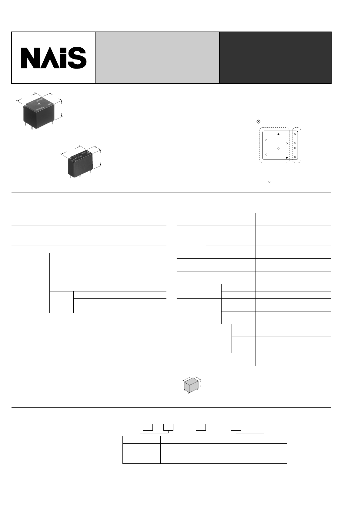
ULTRA SMALL
AUTOMOTIVE RELAY
CT-RELAYS
17.4
.685
14
.551
13.5
.531
FEATURES
• Ultra small size
Twin type: 17.4(L) × 14.0(W) × 13.5(H)mm
.685(L) × .551(W) × .531(H)inch
Slim 1c type: 17.4(L) × 7.2(W) × 13.5(H)mm
.685(L) × .283(W) × .531(H)inch
Twin type (8 terminals)
mm inch
17.4
.685
Slim 1c type
7.2
.283
13.5
.531
• Twin (1 Form C × 2)
Forward/re verse motor control is possib le
with a single relay.
SPECIFICATIONS
Contact
Arrangement
Contact material Silver alloy
Initial contact resistance, max.
(By voltage drop 6 V DC 1 A)
Initial contact voltage drop, max. 0.2 V (at 10 A switching)
Nominal switching
capacity
Rating
Max. carrying current
Mechanical (at 120 cpm) Min. 10
Expected life
(min. operation)
Electrical
Resistive load Min. 10
Motor load
Coil
Nominal operating power 800 mW
Remarks
* Specifications will vary with foreigh standards certification ratings.
1
At nominal switching capacity, operating frequency: 1s ON, 9s OFF
*
2
*
N.O.: at 5 A (steady), 25 A (inrush)/N.C.: at 20 A (brake) 14 V DC, operating frequency: 0.5s ON, 9.5s OFF
3
At 25A 14 V DC (Motor lock), operating frequency: 0.5s ON, 9.5s OFF
*
4
*
Measurement at same location as "Initial breakdown voltage " section
5
Detection current: 10mA
*
6
*
Excluding contact bounce time
7
Half-wave pulse of sine wave: 11ms; detection: 10 µ s
*
8
*
Half-wave pulse of sine wave: 6ms
9
Detection time: 10 µ s
*
1 Form C × 2 (H bridge),
1 Form C
100m Ω
N.O.: 20 A 14 V DC
N.C.: 10 A 14 V DC
35 A for 2 minutes,
25 A for 1 hour
(14 V, at 20 ° C 68 ° F)
7
5
1
*
5
Min. 2 × 10
Min. 10
2
*
5
3
*
• Simple footprint enables ease of PC
board layout
10 terminals layout
Contact
terminal
Coil
terminal
= 8 terminals
Characteristics
Max. operating speed
(at nominal switching capacity)
Initial insulation resistance*
Initial
breakdown
voltage*
Operate time*
Between open
contacts
Between contacts
5
and coil
6
4
Min. 100 M Ω (at 500 V DC)
(at nominal voltage) (at 20 ° C 68 ° F)
Release time (without diode)*
6
(at nominal voltage) (at 20 ° C 68 ° F)
Shock resistance
Vibration
resistance
Functional*
Destructive*
Functional*
Destructive*
Conditions for operation, transport and stor-
11
age*
(Not freezing and
condensing at low temperature)
Unit weight
10
*
Time of vibration for each direction;
X
11
Refer to 5. Conditions for operation, transport and storage mentioned in
*
AMBIENT ENVIRONMENT (Page 61)
X, Y, direction: 2 hours
Y
Z direction: 4 hours
Z
7
8
9
10
Min. 1,000 m/s
Ambient
temp
Humidity 5 to 85% R.H.
Approx. 8.0g .28oz (Twin type)
Approx. 4.0g .14oz (Slim 1c type)
6 cpm
500 Vrms for 1 min.
500 Vrms for 1 min.
Max. 10ms (Initial)
Max. 10ms (Initial)
Min. 100 m/s
10 to 100 Hz,
Min. 44.1m/s
10 to 500 Hz,
Min. 44.1m/s
2
2
2
{4.5G}
2
{4.5G}
–40 ° C to +85 ° C
–40 ° F to +185 ° F
{10G}
{100G}
TYPICAL
APPLICATIONS
• Power windows
• Auto door lock
• Power sunroof
• Electrically powered mirrors
364
ORDERING INFORMATION
CT 1 12AEx.
Product name
CT
Standard packing; 1 Form C: Carton(tube package) 30pcs. Case 1,500pcs.
Contact arrangement
1: 1 Form C
Coil voltage (V DC)
12: 12
2: 1 Form C × 2 (8 terminals type)
5: 1 Form C × 2 (10 terminals type)
1 Form C × 2: Carton(tube package) 30pcs. Case 900pcs.
TYPES AND COIL DATA (at 20 ° C 68 ° F)
Contact
arrangement
Part No.
1c ACT112 12
1c × 2
(8 terminals type)
1c × 2
(10 terminals type)
ACT212 12
ACT512 12
Nominal
voltage,
V DC
Pick-up
voltage,
V DC (max.)
(Initial)
7.2
(Initial)
7.2
(Initial)
7.2
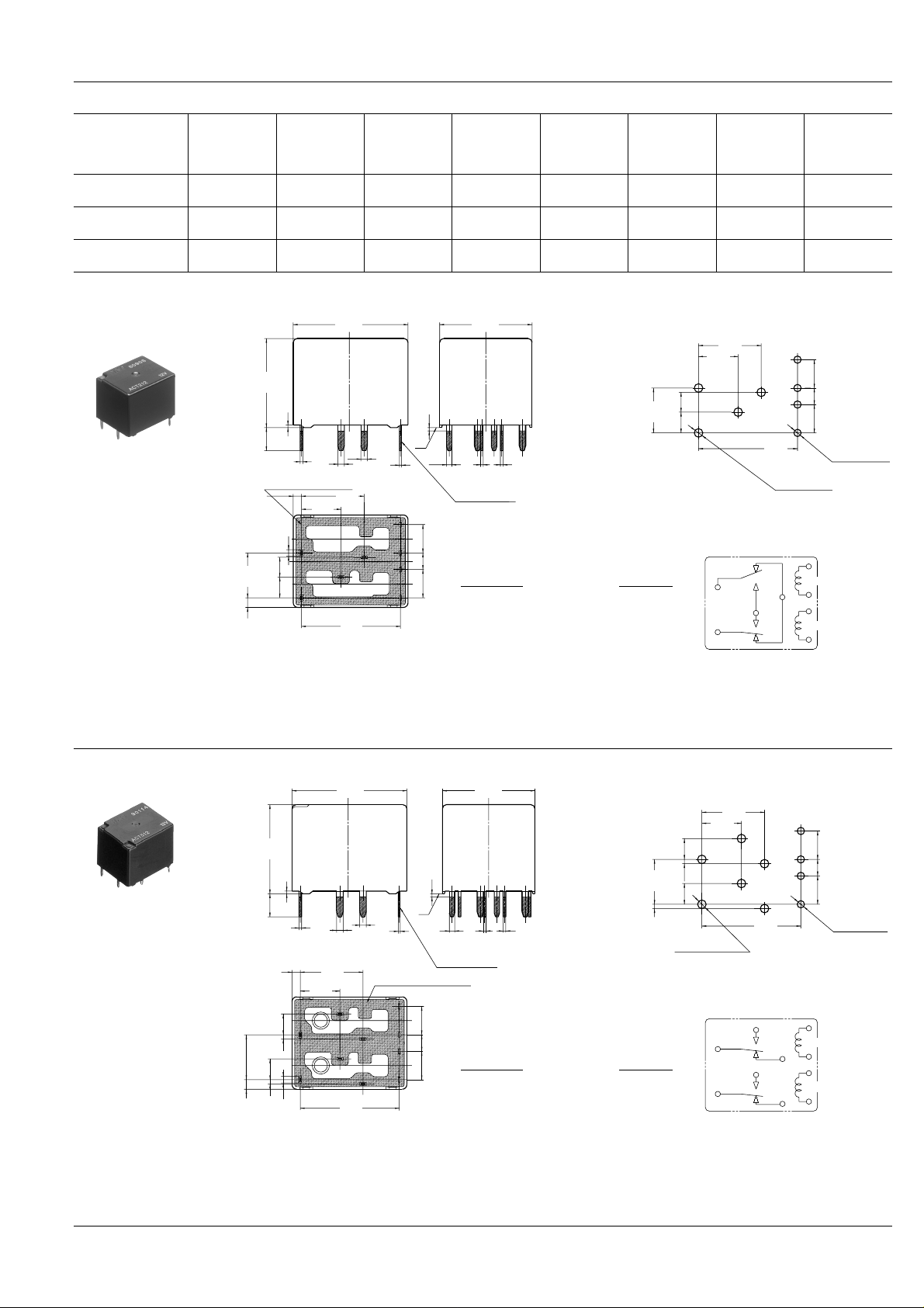
DIMENSIONS
1. Twin type (8 terminals)
13.5
.531
0.4
.016
3.5
.138
0.4
.016
Sealed by epoxy resin
1.25
.049
1
.039
3
6.8
.118
.268
3.15
.124
1.45
.057
.039
.236
1
6
17.4
.685
9.5
.374
JAPAN
15
.591
.039
Max. 1.0
.039
*A
1
0.3
.012
4.3
.169
2.5
.098
4.3
.169
0.8
.031
Ω ( ±
Drop-out
voltage,
resistance,
V DC (min.)
(Initial)
1.0
(Initial)
1.0
(Initial)
1.0
14
.551
0.4
0.4
.016
.016
Pre-soldering
Dimension:
Max. 1mm .039 inch:
Coil
10%)
180 53.3 800 10 to 16
180 53.3 800 10 to 16
180 53.3 800 10 to 16
Nominal
operating
current,
mA ( ± 10%)
.118
6.8
.268
3.15
.124
Tolerance
0.1 ± .004
1 to 3mm .039 to .118 inch: ± 0.2 ± .008
Min. 3mm .118 inch:
0.3 ± .012
±
±
±
±
Nominal
operating
power,
mW
PC board pattern (Bottom view)
9.5
.374
6
.236
3
15
.591
+0.1
0
4-1.4 dia
+0.04
4-.055 dia
0
Tolerance: ± 0.1 ± .004
Schematic (Bottom view)
COM
NO
COM
COIL
NC
COIL
CT
Usable
voltage range,
V DC
mm inch
4.3
.169
2.5
.098
4.3
.169
+0.1
0
4-1.1 dia
+0.04
4-.043 dia
0
* Dimensions (thickness and width) of terminal specified in this catalog is measured before pre-soldering.
Intervals between terminals is measured at A surface level.
2. Twin type (10 terminals)
6.8
.268
1.45
.057
.138
3.15
.124
3.5
1.25
.049
0.65
.026
13.5
.531
3.15
.124
0.65
.026
0.4
.016
0.4
.016
1
.039
.039
.236
6
1
9.5
.374
17.4
.685
1
.039
Sealed by epoxy resin
JAPAN
JAPAN
15
.591
0.3
.012
Max. 1.0
.039
*A
4.3
.169
2.5
.098
4.3
.169
14
.551
0.4
.016
0.4
.016
0.8
.031
Pre-soldering
Dimension:
Max. 1mm .039 inch:
1 to 3mm .039 to .118 inch: ± 0.2 ± .008
Min. 3mm .118 inch:
6.8
.268
0.65
.026
Tolerance
0.1 ± .004
0.3 ± .012
PC board pattern (Bottom view)
9.5
.374
6
3.15
.124
0.65
.026
3.15
.124
.236
+0.1
0
6-1.4 dia
+0.04
6-.055 dia
0
15
.591
Tolerance: ± 0.1 ± .004
Schematic (Bottom view)
NO
COM
NO
COM
NC
NC
COIL
COIL
4.3
.169
2.5
.098
4.3
.169
+0.1
0
4-1.1 dia
4-.043 dia
+0.04
0
* Dimensions (thickness and width) of terminal specified in this catalog is measured before pre-soldering.
Intervals between terminals is measured at A surface level.
365
 Loading...