

Page 1
REFERENCE MANUAL
POWER AMPLIFIERS
ENGLISH
Page 2

Contents
Section Page
Contents
1 Connections E1
1.1 Interconnect Cables E1
1.2 Loudspeaker Cables E1
2 Mains Power E1
2.1 Mains Plug Wiring E1
2.2 Equipment Fuses E1
2.3 Non-rewirable Mains Plugs E1
2.4 Mains Circuits and Cables E1
3 General Installation E2
3.1 Siting The Equipment E2
3.2 Switching On E2
3.3 Running In E2
3.4 Radio Interference E2
3.5 Lightning Precautions E2
3.6 Problems? E2
3.7 Service and Updates E2
4 NAP 500 Installation and Operation E3
4.1 General Connections Notes E3
4.2 Protection Notes E3
4.3 Loudspeaker Cable and Connectors E3
5 NAP 500 Connections E4
5.1 NAP 500 Connected to NAP 500PS E4
6 NAP 300 Installation and Operation E5
6.1 General Connections Notes E5
6.2 Protection Notes E5
6.3 Loudspeaker Cable and Connectors E5
7 NAP 300 Connections E6
7.1 NAP 300 Connected to NAP 300PS E6
8 NAP 250 Installation and Operation E7
8.1 General Connections Notes E7
8.2 Protection Notes E7
8.3 Loudspeaker Cable and Connectors E7
9 NAP 250 Connections E7
9.1 NAP 250 Rear E7
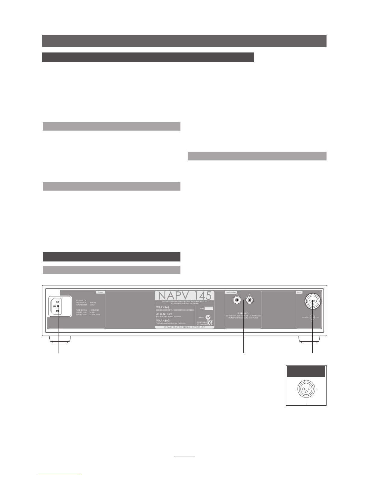
10 NAPV 145 Installation and Operation E8
10.1 General Connections Notes E8
10.2 Protection Notes E8
10.3 Loudspeaker Cable and Connectors E8
11 NAPV 145 Connections E8
11.1 NAPV 145 Rear E8
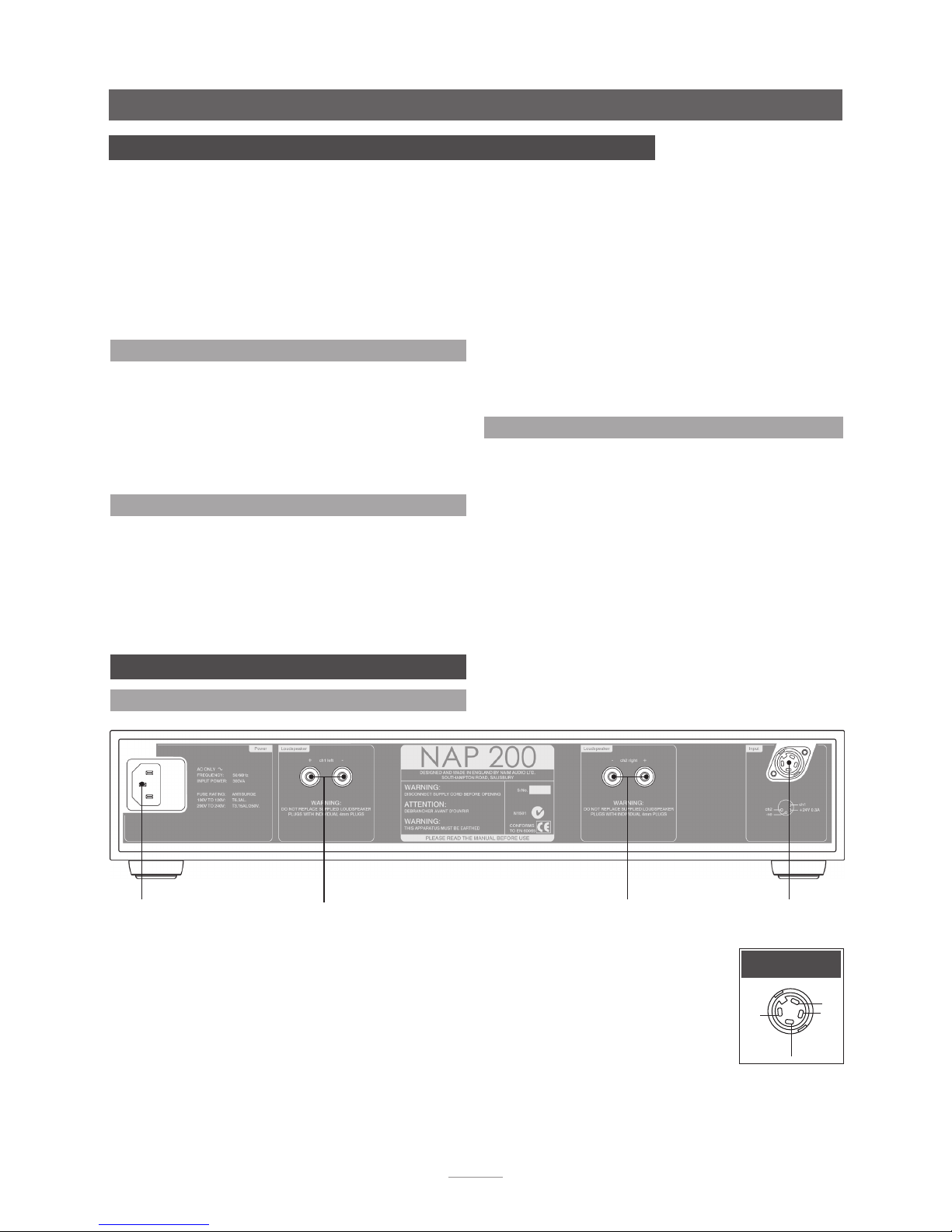
12 NAP 200 Installation and Operation E9
12.1 General Connections Notes E9
12.2 Protection Notes E9
12.3 Loudspeaker Cable and Connectors E9
13 NAP 200 Connections E9
13.1 NAP 200 Rear E9
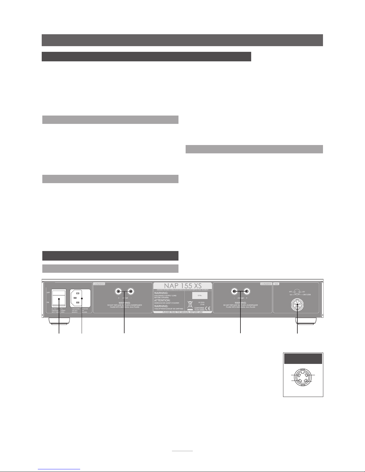
14 NAP 155 XS Installation and Operation E10
14.1 General Connections Notes E10
14.2 Protection Notes E10
14.3 Loudspeaker Cable and Connectors E10
15 NAP 155 XS Connections E10
15.1 NAP 155 XS Rear E10
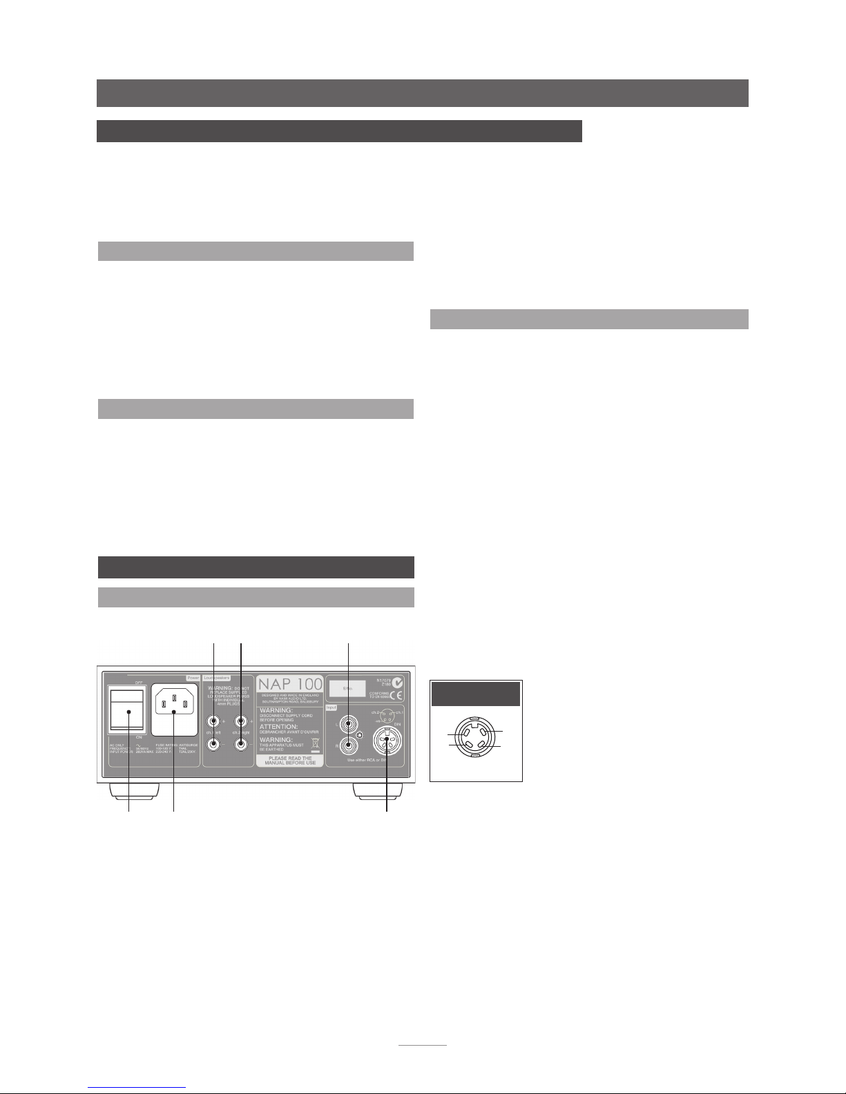
16 NAP 100 Installation and Operation E11
16.1 General Connections Notes E11
16.2 Protection Notes E11
16.3 Loudspeaker Cable and Connectors E11
17 NAP 100 Connections E11
17.1 NAP 100 Rear E11
18 Specifications E12
19 Declaration of Conformity E13
20 Statutory Safety Warnings E13
Page 3

E1
1 Connections
It is important for both safety and performance that
the standard cables supplied are not modified.
1.1 Interconnect Cables
If options are available with your equipment and installation,
DIN interconnect sockets should be used in preference to RCA
Phono sockets. One end of each Naim interconnect cable is
marked with a band to establish its correct orientation. The band
denotes the end that connects to the signal source. Naim Hi-Line
interconnect cables will provide the best results.
Interconnect plugs and sockets should be kept clean and free
from corrosion. The easiest way to clean them is to switch off
the equipment, pull the plugs out of their sockets, and push
them back in again. Contact cleaners and “enhancers” should not
be used as the film they deposit may degrade the sound.
1.2 Loudspeaker Cables
Loudspeaker cables are vitally important. They should each be
at least 3.5 metres long and of equal length. The recommended
maximum is normally 20 metres although longer cables may be
viable with some Naim amplifiers.
Some Naim amplifiers are designed only to work with Naim
loudspeaker cable and using alternatives may degrade the
performance or even damage the amplifier. Other Naim
amplifiers can be used with any high quality loudspeaker cable
although we recommend that Naim loudspeaker cable is used.
Naim loudspeaker cable is directional and should be oriented so
that the printed arrow points towards the speakers. The Naim
loudspeaker connectors supplied are designed to comply with
European safety legislation and must be used.
Contact your local retailer or distributor for further advice on
loudspeaker cables and connectors.
2 Mains Power
Where fused plugs are used 13 amp fuses should be
fitted. Fuses of a lower rating will fail after a period of
use. Do not wire voltage dependent resistors or noise
suppressors into mains plugs. They degrade the mains
supply and the sound.
2.1 Mains Plug Wiring
In some territories a mains plug may need to be fitted to the
supplied mains lead. As the colours of the wires in the mains
lead may not correspond with the coloured markings identifying
the terminals in the plug proceed as follows:
The wire coloured GREEN-AND-YELLOW must be connected to
the terminal in the plug marked by the letter E or by the safety
earth symbol or coloured GREEN or GREEN and YELLOW.
The wire coloured BLUE must be connected to the terminal in
the plug marked with the letter N or coloured BLACK.
The wire coloured BROWN must be connected to the terminal in
the plug marked with the letter L or coloured RED.
2.2 Equipment Fuses
Mains powered Naim Audio equipment is fitted with a mains
fuse on the rear panel adjacent to the mains input socket.
Replace it if necessary only with the spare fuse supplied or with
an identical fuse. Repeated failure of the fuse points to a fault
that should be investigated by your retailer or Naim itself.
2.3 Non-rewirable Mains Plugs
If a non-rewirable plug is cut from a mains lead (for whatever
purpose) the plug MUST be disposed of in a way to render it
totally useless. Considerable shock hazard exists if the cut-off
plug is inserted into a mains outlet.
2.4 Mains Circuits and Cables
A hi-fi system usually shares a mains circuit with other
household equipment some of which can cause distortion of the
mains waveform. This distortion can in turn lead to mechanical
hum from mains transformers. Some Naim transformers are
large in size, making them relatively sensitive to such distortion,
and it may be necessary to take account of transformer hum
when siting your equipment.
Transformer hum is not transmitted through the speakers and
has no effect on the performance of the system; however, a
separate mains circuit may reduce it. Such a circuit (ideally
with a 30 or 45 Amp rating) will also generally improve system
performance. Advice on the installation of a separate mains
circuit should be sought from a qualified electrician.
Use only the mains leads and plugs supplied or the Naim
PowerLine mains cable.
Introduction
Naim Audio products are conceived with performance as the top priority. Careful
installation will help ensure that their full potential is achieved. This manual covers
all power amplifiers. It begins with some general installation notes. Product specific
information begins in Section 4.
Note: Please read
the Statutory Safety
Warnings found at the
end of this manual.
Page 4

E2
3 General Installation
Naim equipment is designed to offer the finest
performance possible avoiding compromise wherever
practical. This can lead to circumstances that may
be unfamiliar. The notes that follow contain advice
specifically related to Naim equipment as well as more
general warnings about the use of domestic audio
products. Please read them carefully.
3.1 Siting The Equipment
In order to reduce the risk of hum audible from the loudspeakers,
power supplies and power amplifiers should be located a
reasonable distance away from other equipment. The maximum
separation distance for connected equipment is that allowed by
the standard interconnect lead.
Some Naim equipment is extremely heavy. Check the weight
of the equipment prior to lifting and if necessary use more than
one person so that it can be moved safely. Ensure that your
equipment rack or table can easily support the weight and is
stable.
3.2 Switching On
Source components and power supplies should be switched on
before the power amplifiers. Always switch amplifiers off and
wait a minute before connecting or disconnecting any leads.
Always use the power switch on the product rather than a mains
outlet switch.
A “thump” may be heard from the loudspeakers as power
amplifiers are switched on. This is normal, will not cause any
loudspeaker damage and does not point to any fault or problem.
A mild “pop” may also be heard shortly after equipment is
switched off.
3.3 Running In
Naim equipment takes a considerable time to run in before
it performs at its best. The duration varies, but under some
conditions the sound may continue to improve for over a month.
Better and more consistent performance will be achieved if
the system is left switched on for long periods. It is worth
remembering however that equipment left connected to the
mains can be damaged by lightning.
3.4 Radio Interference
In some circumstances, depending on where you live and the
earthing arrangements in your home, you may experience
radio frequency interference. Controls on broadcasting in some
territories allow very high levels of radio frequency radiation and
both the choice and exact siting of equipment may be critical.
Susceptibility to radio frequency interference is related to the
wide internal bandwidth necessary for high sound quality. A
radio frequency filter kit is available for some Naim equipment
but sound quality will be progressively compromised as more
elements of the kit are fitted.
3.5 Lightning Precautions
Your Naim hi-fi system can be damaged by lightning and should
be turned off and disconnected from the mains when there is
risk of lightning strike. For complete protection all mains plugs
and any aerial cables should be disconnected when not in use.
3.6 Problems?
Consumer protection varies from country to country. In
most territories a retailer must be prepared to take back any
equipment he has sold if it cannot be made to work satisfactorily.
A problem may be due to a fault in the system or its installation
so it is essential to make full use of your dealer’s diagnostic skills.
Please contact your local distributor, or Naim Audio directly, if
any difficulties cannot be resolved.
Some Naim equipment is made in special versions for
different territories and this makes it impracticable to arrange
international guarantees. Please establish the local guarantee
arrangements with your retailer. Contact Naim Audio directly for
help and advice if necessary.
3.7 Service and Updates
It is essential that repairs and updates are only carried out by
an authorised Naim retailer or at the factory by Naim itself.
Many components are custom made, tested or matched and
appropriate replacements are often unobtainable from other
sources.
Direct contact to Naim for service or update information should
be made initially through Customer Services:
Please quote the product serial number (found on its rear panel)
in all correspondence.
Introduction
Page 5

E3
NAP 500
4.1 General Connections Notes
The mains earth (ground) should always be connected regardless
of what other equipment is used in conjunction with Naim power
amplifiers. This only grounds the case and the electrostatic
screen within the transformer, and is not connected to the signal
negative. In order to avoid hum loops, the signal negative of the
whole system should be connected to the mains earth (ground)
in one place.
Note: Each channel of the NAP 500 is a “bridged” amplifier, so
none of the speaker outlet sockets (+ or -) are at earth potential.
Avoid connecting mains powered equipment such as electrostatic
speakers, sub-woofers and headphone energisers that do not
have a floating earth. No plug which is connected directly or
indirectly to earth potential should be attached to any speaker
outlet (+ or -).
4.2 Protection Notes
In the NAP 500 the fan speed is increased in response to an
increase in amplifier dissipation. If the amplifier reaches 70°C
due to prolonged running at high level or to airflow being
blocked, the output will be interrupted and the fan will run at full
speed until it has cooled down. This may take a few minutes.
It is not necessary to switch the amplifier off, but it may be
advisable to mute the preamplifier or turn the volume down to
avoid surprises when it comes back on.
OPERATION OF THE AMPLIFIER’S THERMAL PROTECTION
SUGGESTS PROLONGED USE AT TOO HIGH A VOLUME
LEVEL. YOUR LOUDSPEAKERS MAY BE AT RISK IF THIS IS
THE CASE. THE VOLUME SHOULD BE REDUCED.
4 NAP 500 Installation and Operation
The NAP 500 and NAP 500PS should be installed on a dedicated equipment stand intended
for the purpose and should be in their final location before connecting cables or switching
on. Switch on the source and preamplifier components, with the volume turned down, before
switching on the NAP 500. The NAP 500 power button is located on the front panel of the
NAP 500PS Power Supply.
Care should be taken when siting the NAP 500 to ensure that the top and bottom ventilation
grids are not blocked.
The NAP 500 and NAP 500PS are very heavy and care should be taken when lifting or moving
them. Make sure that the surface they are to be placed on can support the full weight.
4.3 Loudspeaker Cable and Connectors
Only Naim Audio speaker cable should be used to connect a
loudspeaker to the output of the NAP 500. Custom Naim Audio
loudspeaker connectors are supplied to make the connection
and in order to comply with current European safety regulations
these should always be used.
DAMAGE TO THE AMPLIFIER MAY RESULT IF “HIGH
DEFINITION” CABLE OR ANY OTHER SPECIAL CABLE IS USED
TO CONNECT THE LOUDSPEAKERS.
Ensure when connecting speakers that they are “in phase”. That
is, the positive and negative connection orientation at both the
speaker and amplifier ends of the cable is the same for both
channels.
Page 6
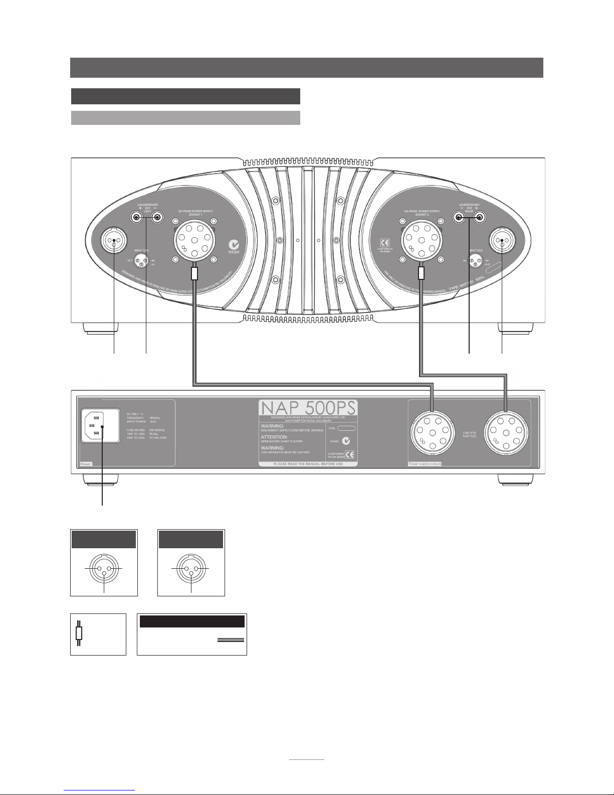
E4
NAP 500
signal
input ch1 (L)
signal
input ch2(R)
mains input
and fuse
left
speaker
right
speaker
cable
direction
marker
NAP 500PS Burndy
Interconnect Cables
Input Ch1 Input Ch2
ch1
-ve
nc
nc ch2
-ve
5 NAP 500 Connections
5.1 NAP 500 Connected to NAP 500PS
Page 7

E5
6.1 General Connections Notes
The negative input and output connections for each channel are
common. The mains earth (ground) should always be connected
regardless of what other equipment is used in conjunction
with Naim power amplifiers. This only grounds the case and
the electrostatic screen within the transformer, and is not
connected to the signal negative. In order to avoid hum loops,
the signal negative of the whole system should be connected to
the mains earth (ground) in one place.
6.2 Protection Notes
In the NAP 300 the fan speed is increased in response to an
increase in amplifier dissipation. If the amplifier reaches 70°C
due to prolonged running at high level or to airflow being
blocked, the output will be interrupted and the fan will run at full
speed until it has cooled down. This may take a few minutes.
It is not necessary to switch the amplifier off, but it may be
advisable to mute the preamplifier or turn the volume down to
avoid surprises when it comes back on.
OPERATION OF THE AMPLIFIER’S THERMAL PROTECTION
SUGGESTS PROLONGED USE AT TOO HIGH A VOLUME
LEVEL. YOUR LOUDSPEAKERS MAY BE AT RISK IF THIS IS
THE CASE. THE VOLUME SHOULD BE REDUCED.
6 NAP 300 Installation and Operation
The NAP 300 and NAP 300PS should be installed on a dedicated equipment stand intended
for the purpose and should be in their final location before connecting cables or switching
on. Switch on the source and preamplifier components, with the volume turned down, before
switching on the NAP 300. The NAP 300 power button is located on the front panel of the
NAP 300PS Power Supply.
Care should be taken when siting the NAP 300 to ensure that the underside fan inlet and rear
outlet are not obstructed.
The NAP 300 and NAP 300PS are heavy and care should be taken when lifting or moving
them. Make sure that the surface they are to be placed on can support the full weight.
6.3 Loudspeaker Cable and Connectors
Only Naim Audio speaker cable should be used to connect a
loudspeaker to the output of the NAP 300. Custom Naim Audio
loudspeaker connectors are supplied to make the connection
and in order to comply with current European safety regulations
these should always be used.
DAMAGE TO THE AMPLIFIER MAY RESULT IF “HIGH
DEFINITION” CABLE OR ANY OTHER SPECIAL CABLE IS
USED TO CONNECT THE LOUDSPEAKERS.
Ensure when connecting speakers that they are “in phase”. That
is, the positive and negative connection orientation at both the
speaker and amplifier ends of the cable is the same for both
channels.
NAP 300
Page 8
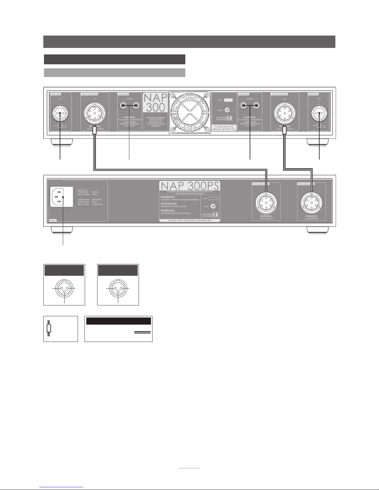
E6
NAP 300
signal
input ch1(L)
signal
input ch2(R)
mains input
and fuse
left
speaker
right
speaker
cable
direction
marker
NAP 300PS Burndy
Interconnect Cables
Input Ch1 Input Ch2
ch1
-ve
nc
nc ch2
-ve
7 NAP 300 Connections
7.1 NAP 300 Connected to NAP 300PS
Page 9
E7
8.1 General Connections Notes
The negative input and output connections are all common. The
mains earth should always be connected regardless of what
other equipment is used. This only grounds the case and the
electrostatic screen within the transformer, and is not connected
to the signal negative. In order to avoid hum loops, the signal
negative of the whole system should be connected to the mains
earth (ground) in one place.
8.2 Protection Notes
If the amplifier’s external case reaches 70°C due to prolonged
running at high power, the mains supply will be interrupted and
the illuminated logo will switch off until the amplifier has cooled
down. This may take up to thirty minutes.
8 NAP 250 Installation and Operation
The NAP 250 should be installed on a dedicated equipment stand intended for the purpose
and should be in its final location before connecting cables or switching on. Switch on the
source and preamplifier components, with the volume turned down, before switching on the
NAP 250. The NAP 250 power button is located on the front panel.
The NAP 250 is heavy and care should be taken when lifting or moving it. Make sure that the
surface it is to be placed on can support the full weight.
OPERATION OF THE AMPLIFIER’S THERMAL PROTECTION
SUGGESTS PROLONGED USE AT TOO HIGH A VOLUME
LEVEL. YOUR LOUDSPEAKERS MAY BE AT RISK IF THIS IS THE
CASE. THE VOLUME SHOULD BE REDUCED.
8.3 Loudspeaker Cable and Connectors
Only Naim Audio speaker cable should be used to connect a
loudspeaker to the output of the NAP 250. Custom Naim Audio
loudspeaker connectors are supplied to make the connection
and in order to comply with current European safety regulations
these should always be used.
DAMAGE TO THE AMPLIFIER MAY RESULT IF “HIGH
DEFINITION” CABLE OR ANY OTHER SPECIAL CABLE IS USED
TO CONNECT THE LOUDSPEAKERS.
Ensure when connecting speakers that they are “in phase”. That
is, the positive and negative connection orientation at both the
speaker and amplifier ends of the cable is the same for both
channels.
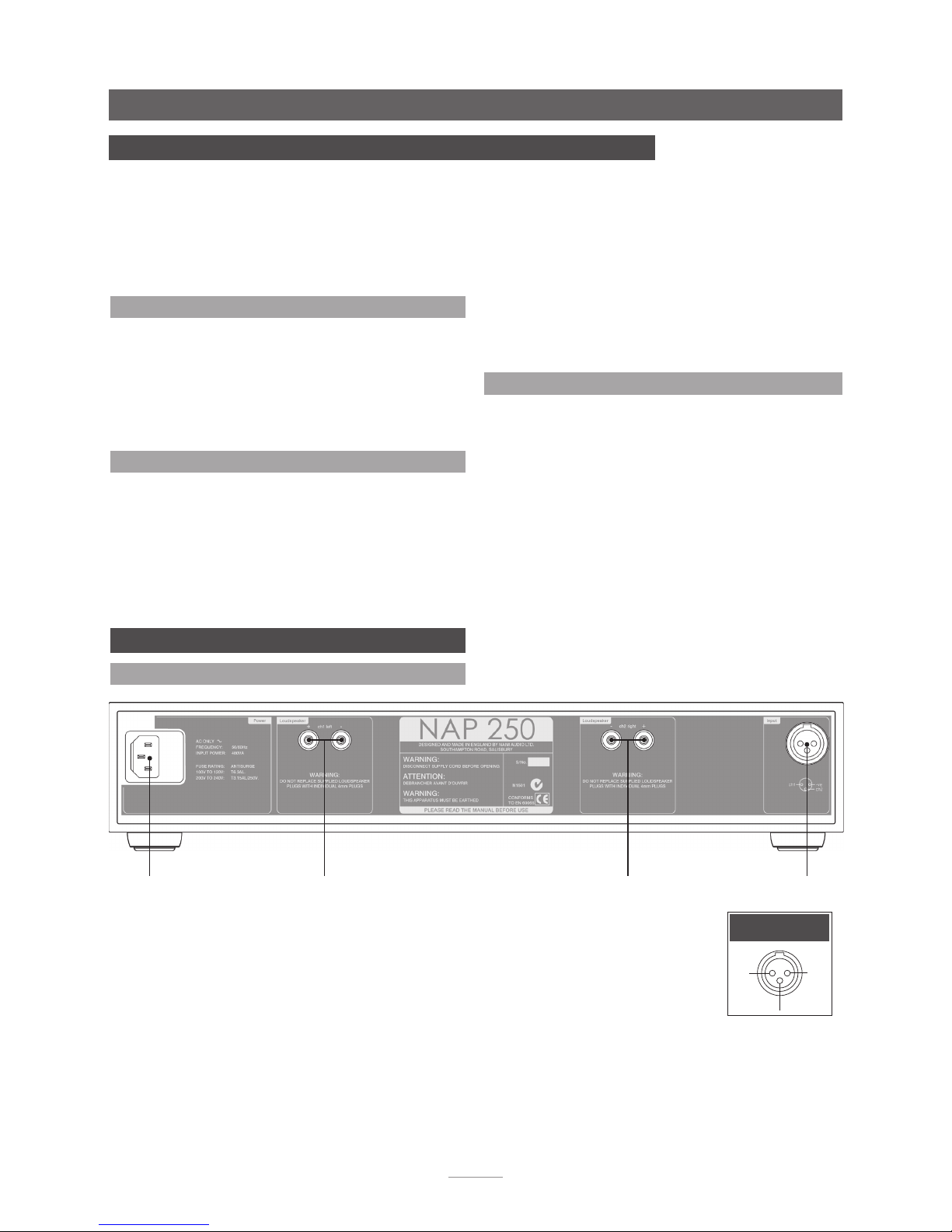
NAP 250
ch2
-ve
ch1
Input
mains input
and fuse
signal input
ch1(L) & ch2(R)
9 NAP 250 Connections
9.1 NAP 250 Rear
left
speaker
right
speaker
Page 10
E8
10.1 General Connections Notes
The negative input and output connections are all common. The
mains earth should always be connected regardless of what
other equipment is used. This only grounds the case and the
electrostatic screen within the transformer, and is not connected
to the signal negative. In order to avoid hum loops, the signal
negative of the whole system should be connected to the mains
earth (ground) in one place.
10.2 Protection Notes
If the amplifier’s external case reaches 70°C due to prolonged
running at high power, the mains supply will be interrupted and
the illuminated logo will switch off until the amplifier has cooled
down. This may take up to thirty minutes.
10 NAPV 145 Installation and Operation
The NAPV 145 is a mono power amplifier intended for use in audio-visual systems. The NAPV
145 should be installed on a dedicated equipment stand intended for the purpose and should
be in its final location before connecting cables or switching on. Switch on the source and
preamplifier components, with the volume turned down, before switching on the NAPV 145.
The NAPV 145 power button is located on the front panel.
The NAPV 145 is heavy and care should be taken when lifting or moving it. Make sure that the
surface it is to be placed on can support the full weight.
OPERATION OF THE AMPLIFIER’S THERMAL PROTECTION
SUGGESTS PROLONGED USE AT TOO HIGH A VOLUME
LEVEL. YOUR LOUDSPEAKERS MAY BE AT RISK IF THIS IS THE
CASE. THE VOLUME SHOULD BE REDUCED.
10.3 Loudspeaker Cable and Connectors
Only Naim Audio speaker cable should be used to connect a
loudspeaker to the output of the NAPV 145. Custom Naim Audio
loudspeaker connectors are supplied to make the connection
and in order to comply with current European safety regulations
these should always be used.
DAMAGE TO THE AMPLIFIER MAY RESULT IF “HIGH
DEFINITION” CABLE OR ANY OTHER SPECIAL CABLE IS USED
TO CONNECT THE LOUDSPEAKERS.
Ensure when connecting speakers that they are “in phase”. That
is, the positive and negative connection orientation at both the
speaker and amplifier ends of the cable is the same for both
channels.
mains input
and fuse
signal input
NAPV 145
speaker
11 NAPV 145 Connections
11.1 NAPV 145 Rear
nc
-ve
i/p
Input
Page 11
E9
12.1 General Connections Notes
The negative input and output connections are all common.
The mains earth should always be connected regardless of
what other equipment is used. This only grounds the case
and the electrostatic screen within the transformer, and is not
connected to the signal negative. In order to avoid hum loops,
the signal negative of the whole system should be connected to
the mains earth (ground) in one place.
12.2 Protection Notes
If the amplifier’s external case reaches 70°C due to prolonged
running at high power, the mains supply will be interrupted and
the illuminated logo will switch off until the amplifier has cooled
down. This may take up to thirty minutes.
12 NAP 200 Installation and Operation
The NAP 200 should be installed on a dedicated equipment stand intended for the purpose
and should be in its final location before connecting cables or switching on. Switch on the
source and preamplifier components, with the volume turned down, before switching on the
NAP 200. The NAP 200 power button is located on the front panel.
The NAP 200 can provide power for an appropriate Naim Audio preamplifier. The power
supply output is carried on the DIN input socket.
The NAP 200 is heavy and care should be taken when lifting or moving it. Make sure that the
surface it is to be placed on can support its full weight.
OPERATION OF THE AMPLIFIER’S THERMAL PROTECTION
SUGGESTS PROLONGED USE AT TOO HIGH A VOLUME
LEVEL. YOUR LOUDSPEAKERS MAY BE AT RISK IF THIS IS THE
CASE. THE VOLUME SHOULD BE REDUCED.
12.3 Loudspeaker Cable and Connectors
Only Naim Audio speaker cable should be used to connect a
loudspeaker to the output of the NAP 200. Custom Naim Audio
loudspeaker connectors are supplied to make the connection and
in order to comply with current European safety regulations these
should always be used.
DAMAGE TO THE AMPLIFIER MAY RESULT IF “HIGH
DEFINITION” CABLE OR ANY OTHER SPECIAL CABLE IS USED
TO CONNECT THE LOUDSPEAKERS.
Ensure when connecting speakers that they are “in phase”. That
is, the positive and negative connection orientation at both the
speaker and amplifier ends of the cable is the same for both
channels.
mains input
and fuse
signal input
ch1(L) & ch2(R) and
preamp power supply
ch2
-ve
ch1
24V
0.3A
Input/Preamp
Power Socket
NAP 200
left
speaker
right
speaker
13 NAP 200 Connections
13.1 NAP 200 Rear
Page 12
E10
14.1 General Connections Notes
The negative input and output connections are all common. The
mains earth should always be connected regardless of what
other equipment is used. This only grounds the case and the
electrostatic screen within the transformer, and is not connected
to the signal negative. In order to avoid hum loops, the signal
negative of the whole system should be connected to the mains
earth (ground) in one place.
14.2 Protection Notes
If the amplifier’s external case reaches 70°C due to prolonged
running at high power, the mains supply will be interrupted and
the illuminated logo will switch off until the amplifier has cooled
down. This may take up to thirty minutes.
14 NAP 155 XS Installation and Operation
The NAP 155 XS should be installed on a dedicated equipment stand intended for the purpose
and should be in its final location before connecting cables or switching on. Switch on the
source and preamplifier components, with the volume turned down, before switching on the
NAP 155 XS. The NAP 155 XS power switch is located on the rear panel.
The NAP 155 XS can provide power for an appropriate Naim Audio preamplifier. The power
supply output is carried on the DIN input socket.
OPERATION OF THE AMPLIFIER’S THERMAL PROTECTION
SUGGESTS PROLONGED USE AT TOO HIGH A VOLUME
LEVEL. YOUR LOUDSPEAKERS MAY BE AT RISK IF THIS IS THE
CASE. THE VOLUME SHOULD BE REDUCED.
14.3 Loudspeaker Cable and Connectors
Only Naim Audio speaker cable should be used to connect a
loudspeaker to the output of the NAP 155 XS. Custom Naim
Audio loudspeaker connectors are supplied to make the
connection and in order to comply with current European safety
regulations these should always be used.
DAMAGE TO THE AMPLIFIER MAY RESULT IF “HIGH
DEFINITION” CABLE OR ANY OTHER SPECIAL CABLE IS USED
TO CONNECT THE LOUDSPEAKERS.
Ensure when connecting speakers that they are “in phase”. That
is, the positive and negative connection orientation at both the
speaker and amplifier ends of the cable is the same for both
channels.
mains input
and fuse
signal input
ch1(L) & ch2(R) and
preamp power supply
ch2
ch1
24V
0.25A
Input/Preamp
Power Socket
-ve
power
switch
NAP 155 XS
15 NAP 155 XS Connections
15.1 NAP 155 XS Rear
left
speaker
right
speaker
Note: The NAP 155 XS features various technologies to reduce
microphonic effects. Some movement of the board and sockets
when connecting and disconnecting cables is normal.
Page 13
E11
16.1 General Connections Notes
The mains earth grounds only the case and the electrostatic
screen within the transformer and is not connected to the
signal negative. The mains earth must always be connected to
“ground” regardless of any other equipment used. In order to
avoid hum-loops the signal negative of the whole system should
be connected to the mains earth in one place.
The DIN and RCA signal input sockets are connected in parallel
and should not be used simultaneously.
16.2 Protection Notes
Once installed the NAP 100 is intended to remain permanently
switched on via its rear panel switch. If the internal heatsink
reaches 70°C due to prolonged operation at high volume levels,
the power amplifier circuit will be disabled until the temperature
has fallen. This may take up to thirty minutes.
16 NAP 100 Installation and Operation
The NAP 100 should be installed on a dedicated equipment stand intended for the purpose
and should be in its final location before connecting cables or switching on. Make sure that
the amplifier location allows adequate ventilation. Switch on the source and preamplifier
components, with the volume turned down, before switching on the NAP 100. The NAP 100
power switch is located on the rear panel.
OPERATION OF THE AMPLIFIER’S THERMAL PROTECTION
SUGGESTS PROLONGED USE AT TOO HIGH A VOLUME
LEVEL. YOUR LOUDSPEAKERS MAY BE AT RISK IF THIS IS THE
CASE. THE VOLUME SHOULD BE REDUCED.
16.3 Loudspeaker Cable and Connectors
A stereo set of speaker connection sockets is provided on the
rear panel. Custom Naim Audio loudspeaker connectors are
supplied to make the connection and in order to comply with
current European safety regulations these should always be used.
Naim Audio speaker cable will provide the best results; however,
a wide range of speaker cable types can be used without risk of
damage to the amplifier.
Ensure when connecting speakers that they are “in phase”. That
is, the positive and negative connection orientation at both the
speaker and amplifier ends of the cable is the same for both
channels.
mains input
and fuse
power
switch
ch1
nc
DIN Input -
Ch.1 & Ch.2
ch2
-ve
NAP 100
17 NAP 100 Connections
17.1 NAP 100 Rear
left speaker right speaker
DIN signal input
ch1(L) & ch2(R)
RCA signal input
ch1(L) & ch2(R)
Page 14

E12
Specifications
18 Specifications
NAP 500 NAP 300 NAP 250
Power Output: 140 Watts per channel, 8 90 Watts per channel, 8 80 Watts per channel, 8
Quiescent Consumption: 60VA 27VA 25VA
Voltage Gain: +30dB +29dB +29dB
Input Impedance: 18k 18k 18k
Frequency Response: -3dB @ 1.5Hz and 100kHz -3dB @ 2Hz and 70kHz -3dB @ 2Hz and 65kHz
Power Supply Output: None None None
Dimensions (H x W x D): NAP 500 - 160 × 432 × 375mm NAP 300 - 87 × 432 × 314mm 87 × 432 × 314mm
NAP 500PS - 87 × 432 × 314mm NAP 300PS - 87 × 432 × 314mm
Weight: NAP 500 - 25kg NAP 300 - 10.7kg 15.8kg
NAP 500PS - 15.4kg NAP 300PS - 14.1kg
Mains Supply: 100V, 115V or 230V, 50/60Hz 100V, 115V or 230V, 50/60Hz 100V, 115V or 230V, 50/60Hz
(NAP 500PS) (NAP 300PS)
NAPV 145 NAP 200 NAP 155 XS
Power Output: 80 Watts, 8 (single channel) 70 Watts per channel, 8 60 Watts per channel, 8
Quiescent Consumption: 15VA 11VA 10VA
Voltage Gain: +29dB +29dB +29dB
Input Impedance: 18k 18k 18k
Frequency Response: -3dB @ 2Hz and 65kHz -3dB @ 2Hz and 70kHz -3dB @ 3Hz and 50kHz
Power Supply Output: None 24V, 0.3A 24V, 0.25A
Dimensions (H x W x D): 87 × 432 × 314mm 87 × 432 × 314mm 70 × 432 × 301mm
Weight: 15.8kg 11.6kg 7.5kg
Mains Supply: 100V, 115V or 230V, 50/60Hz 100V, 115V or 230V, 50/60Hz 100V, 115V or 230V, 50/60Hz
NAP 100
Power Output: 50 Watts per channel, 8
Quiescent Consumption: 15VA
Voltage Gain: +29dB
Input Impedance: 18k
Frequency Response: -3dB @ 3.5Hz and 69kHz
Power Supply Output: None
Dimensions (H x W x D): 87 × 207 × 314mm
Weight: 5.6kg
Mains Supply: 100V, 115V or 230V, 50/60Hz
Page 15
E13
Declaration of Conformity
Products that display the crossed-out wheeled bin logo cannot
be disposed of as domestic waste. These products must be
disposed of at facilities capable of re-cycling them
and appropriately handling any waste by-products.
Contact your local authority for details of the
nearest such facility. Appropriate recycling and
waste disposal helps conserve resources and
protects the environment from contamination.
19 Declaration of Conformity
Naim Audio declares that Naim Audio products are in conformance with:
Low Voltage Directive 2006/95/EC
Electromagnetic Compatibility Directive 2004/108/EC
Restriction of Hazardous Substances (RoHS2) Directive 2011/65/EU
Waste of Electrical and Electronic Equipment Directive 2002/96/EC
Energy Related Products (ErP), Directive 2009/125/EC
Naim Audio products comply with the following standards:
EN60065 - Audio, video and similar electronic apparatus - Safety requirements
EN55013 - Sound and television broadcast receivers and associated equipment - Radio disturbance
characteristics
EN55020 - Sound and television broadcast receivers and associated equipment - Immunity
characteristics
EN61000-3-2 - Mains harmonics current emissions
EN61000-3-3 - Mains flicker emissions
20 Statutory Safety Warnings
In order to comply with current European safety regulations it
is essential that the Naim loudspeaker connectors supplied with
amplifiers and loudspeakers are used.
Do not under any circumstances allow anyone to modify your
Naim equipment without first checking with the factory, your
retailer, or your distributor. Unauthorised modifications will
invalidate your guarantee.
Equipment must not be exposed to dripping or splashing and no
objects filled with liquid, such as vases, should be placed on the
equipment.
For your own safety do not under any circumstances open Naim
equipment without first disconnecting it from the mains.
Warning: an apparatus with CLASS I construction shall be
connected to a mains socket outlet with a protective earthing
connection.
Warning: batteries installed shall not be exposed to excessive
heat such as sunshine, fire or the like.
Where the mains plug or an appliance coupler is used as the
disconnect device, the disconnect device shall remain readily
operable. To disconnect the equipment from the mains remove
the mains plug from the mains outlet.
The following label is attached to all mains powered equipment:
WARNING
THIS APPARATUS
MUST BE EARTHED
This equipment has been tested and found to comply with the
relevant EMC and Safety Standards, and, where applicable, also
complies with the limits for a class B digital device, pursuant to
Part 15 of the FCC Rules.
These limits are designed to provide reasonable protection
against harmful interference in a residential installation. This
equipment generates, uses and can radiate radio frequency and,
if not installed and used in accordance with the instructions,
may cause harmful interference to radio communications.
However, there is no guarantee that interference will not occur
in a particular installation. If this equipment does cause harmful
interference to radio or television reception, which can be
determined by turning off and on, the user is encouraged to
try to correct the interference by one or more of the following
measures:
• Reorient or relocate the receiving antenna.
• Increase the separation between the equipment and the
receiver.
• Connect the equipment into an outlet on a circuit different
from that to which the receiver is connected.
• Consult your Naim retailer or an experienced radio/TV
technician for help.
Note
To the fullest extent permitted by applicable law, Naim Audio
Ltd. disclaims all liability for any loss or damages whether real,
incidental or consequential that arise from using this product.
Naim Audio Limited, its agents and representatives, cannot
be held responsible for the loss of any data or content from a
Naim/NaimNet server, however caused.
Naim Audio Ltd, Southampton Road, Salisbury, England SP1 2LN
Tel: +44 (0) 1722 426600 Fax: +44 (0)871 230 1012
W: www.naimaudio.com
Part No. 12-001-0243 Iss. 1E
 Loading...