

Page 1
HD PREAMP
OWNER MANUAL
RELEASE ©2019
Page 2

Page 3

/// Dear music lover
Congratulations, you have just purchased one of the best
preamplifiers ever made! The HD PREAMP was created by an
engineering team with more than 60 years of experience designing
world-class products for the professional audio, national security
and military businesses.
Since its inception in 1951, Nagra has built products that continue
to earn a reputation for delivering ultimate sonic performance.
Numerous awards have been bestowed upon Nagra for its technical
innovation, excellence in design and flawless construction including
three Oscars® and one Emmy®.
The professional and Hi-Fi ranges are both designed by our Research
and Development department. Nagra has launched a Hi-Fi range to
allow the wider public to benefit from technical advances that are
often the sole privilege of professionals. This technology exists in
the service of music, your music. We wish you great moments of
listening pleasure with your HD PREAMP.
Thank you for your trust.
Pascal Mauroux
CEO
Page 4
Page 5

Safety warnings
01
Warranty
Package contents
INSTALLATION OF YOUR HD PREAMP
02
Choosing a location
Horizontality adjustment of the chassis
Powering the HD PREAMP
Connection to the Mains
Connection/Disconnection of LEMO cables
Fuse replacement
HD PREAMP description
Front panel (audio device chassis)
Rear panel (audio device chassis)
Audio inputs
Bypass inputs
Audio outputs
Rear panel (power supply chassis)
About ground post
03
OPERATION OF YOUR HD PREAMP
Power on & Audio input selection
Audio output selection
Nagra modulometer
Light intensity adjustment
Modulometer IN/OUT
Volume control synchronization & warning LED
Mute
IR Remote Control Unit
Use of a universal IR Remote Control Unit
Remote automation
Home automation
Tube ageing
HD PREAMP software update
Case cleaning
TECHNICAL SPECIFICATIONS
04
SUMMARY
Page 6

01
HD PREAMP
Safety warnings
• Read this manual carefully before operating the HD PREAMP.
• Should you have any questions on how to setup or use your HD PREAMP, please
contact your Nagra dealer.
• Audio Technology Switzerland SA declines any responsibility in the event of an
accident caused by the non-observance of these instructions or any other form
of user negligence.
• The HD PREAMP has a specific power supply to work correctly in your country.
The power supply voltage can only be changed at the factory. Make sure you have
the right operating voltage before switching your device ON.
• The HD PREAMP is CLASS I equipment. It is essential that it is connected to a
MAINS socket outlet with a protective earthing connection.
• The HD PREAMP must not be exposed to dripping or splashing liquids and no
objects filled with liquids, such as vases, should be placed on the machine.
• Never try to open your HD PREAMP when it is powered to prevent the risk of
electric shock and burns. Switch it OFF, remove the MAINS cable from the
appliance inlet and wait at least 15 minutes before any intervention into your HD
PREAMP such as for tube exchange or IR Remote Control Unit channel selection.
If you are unsure, please contact your Nagra dealer.
SAFETY WARNINGS WARRANTY//
Page 7

NAGRA HD PREAMP // SAFETY WARNING // 06 + 07
01
Warranty
Audio Technology Switzerland SA certifies that this device has been inspected and
tested before leaving the factory. Every Nagra unit goes through our test laboratory.
The result of the measurements is recorded in the “Protocol” documentation that
comes with your device. We guarantee our products against all manufacturing
defects. For the HD PREAMP, this is for a period of three years from the date of
delivery to the customer (validated by the serial number on the device casing
and the invoice from an official Nagra dealer). This warranty is only valid for the
original purchaser of new equipment. This limited warranty covers the repair and
replacement of defective parts, excluding any other remedy.
The absence of a serial number invalidates the warranty.
We decline any responsibility for damages resulting directly or indirectly from the
use of our products and from the use of any components or spare parts other than
those designated as original/approved parts by Audio Technology Switzerland SA.
As we constantly strive to improve our products, we reserve the right to modify them
or change their specifications without notice.
Package contents
The package of your HD PREAMP includes the following parts:
One ① HD PREAMP audio device chassis
One ① HD PREAMP power supply chassis
Four ④ ceramic balls
One ① user manual
One ① pair of microfiber gloves « Haute Horlogerie »
One ① power cord*
Two ② umbilical cords with LEMO plugs
One ① set of fuses (for 100V~ – 127V~ or 230V~ – 240V~, depending on your country)
One ① remote control unit and its docking station with 3x AA dry cells
Please contact your Nagra dealer should anything be missing.
* Depending on your country, the power cord features either a US, European or Swiss plug.
Page 8
Page 9
Page 10
02
HD PREAMP
Choosing a location
The HD PREAMP is designed exclusively for indoor use in a moderate climate.
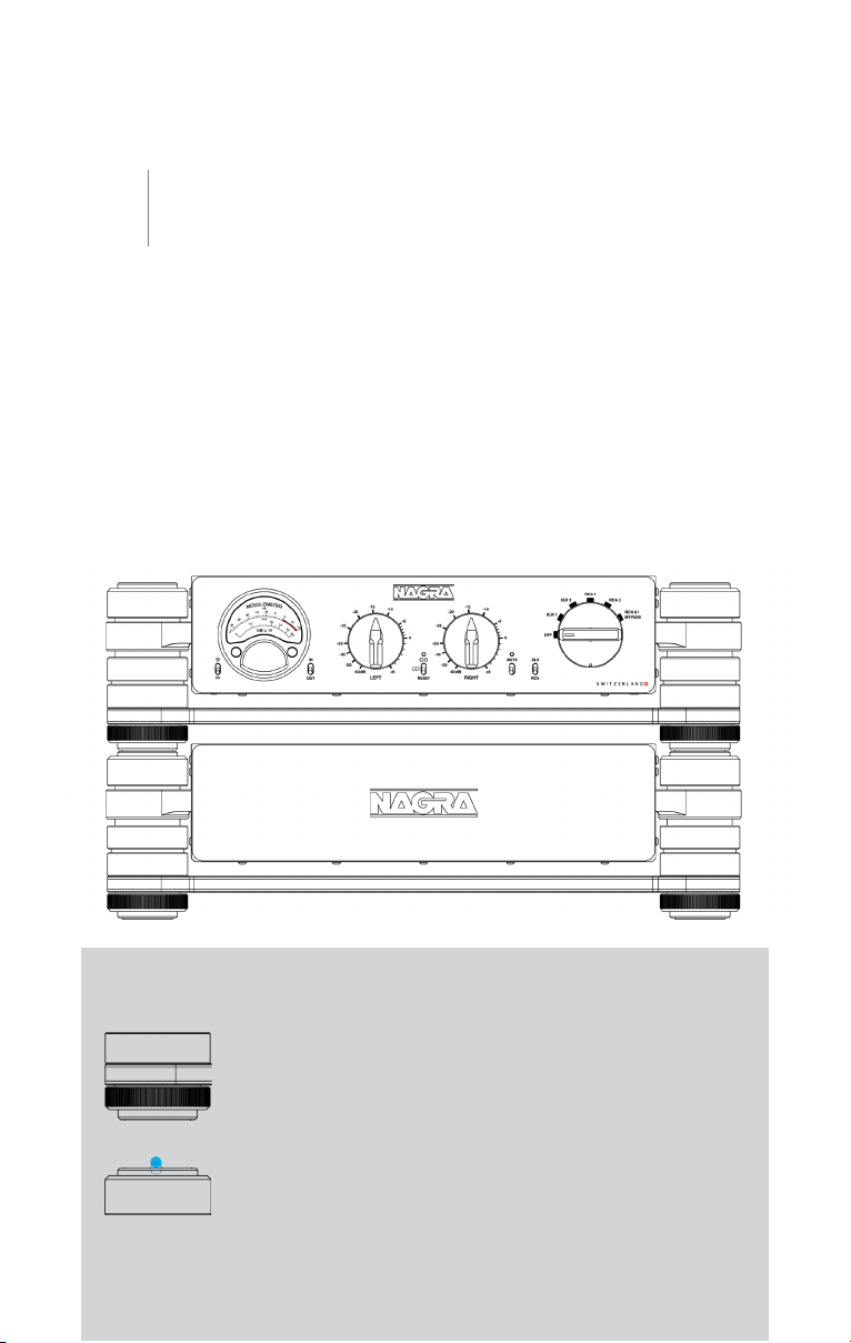
The HD PREAMP is contained in two chassis: one audio device and one power
supply. These chassis feature an anti-vibration base that allows for putting either
one chassis on top of the other or one chassis next to the other, while remaining
completely insensitive to vibration. They must be installed horizontally on a flat, firm
and stable stand. There must be enough space all around the chassis for adequate
ventilation. Ventilation should not be impeded by covering the ventilation openings
with items such as newspapers, table-cloths, curtains, etc.
INSTALLATION OF YOUR HD PREAMP //
ceramic
balls
↓
↓
Horizontality adjustment of the chassis HD PREAMP / HD PSU
Each chassis has four decoupling feet whose height can be
adjusted with a wheel (knurled part). Turning the wheel adjusts
the height of the foot and thus the level of the chassis. When the
chassis are installed one on top of the other, the four feet of the
upper chassis are in contact with the four feet of the lower chassis
through four ceramic balls supplied with the HD PREAMP. The
balls are seated in the small indentations at the top of each foot of
the lower chassis (preferably the power supply chassis).
Page 11
NAGRA HD PREAMP // INSTALLATION // 010 + 011
02
Powering the HD PREAMP
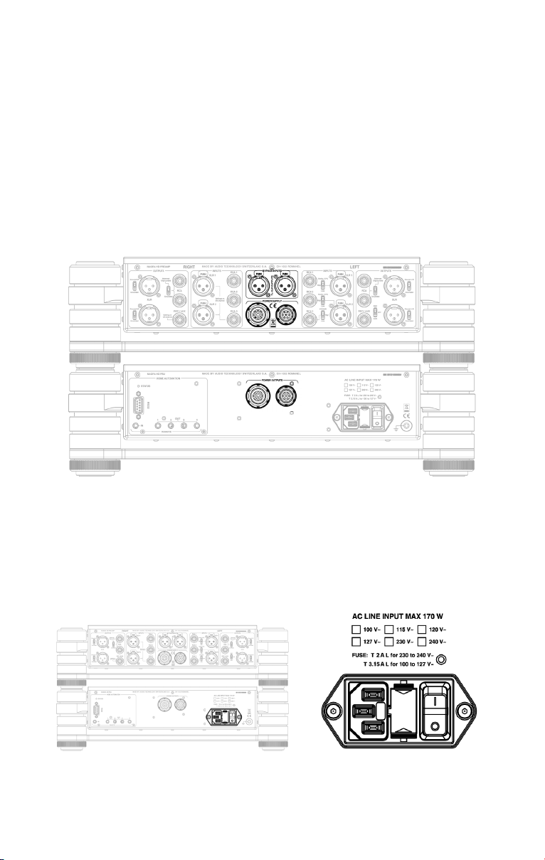
The power cord of the HD PREAMP is connected on the rear panel of its power
supply chassis. The power supply chassis converts the Mains supply into several
different regulated voltages sent to the audio device chassis through two umbilical
cords with LEMO plugs. These umbilical cords are supplied with the HD PREAMP.
↑↓↑
↓
Connection to the Mains
Push the Mains appliance inlet switch at the back of the power supply chassis into the
(OFF) position. Insert the Mains cord into the IEC connector of the power supply chassis.
Page 12
Connection/Disconnection of LEMO cables
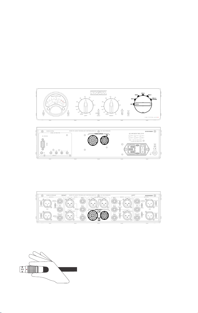
Turn the front selector of the audio device chassis to the OFF position. Insert one
LEMO plug of each umbilical cord into the matching LEMO socket at the back of
the power supply chassis. Please note that the red dot on the LEMO plugs must be
facing up before trying to insert them into the chassis sockets. You will hear a click
indicating that the plug is securely locked in.
↑
↑↑↑
Repeat the procedure with the other ends of the umbilical cords, inserting them into
the LEMO sockets at the back of the audio device chassis in the same way.
↑
↑
To disconnect the LEMO plug, hold the knurled
section of the plug and pull it backwards.
Page 13
NAGRA HD PREAMP // INSTALLATION // 012 + 013
02
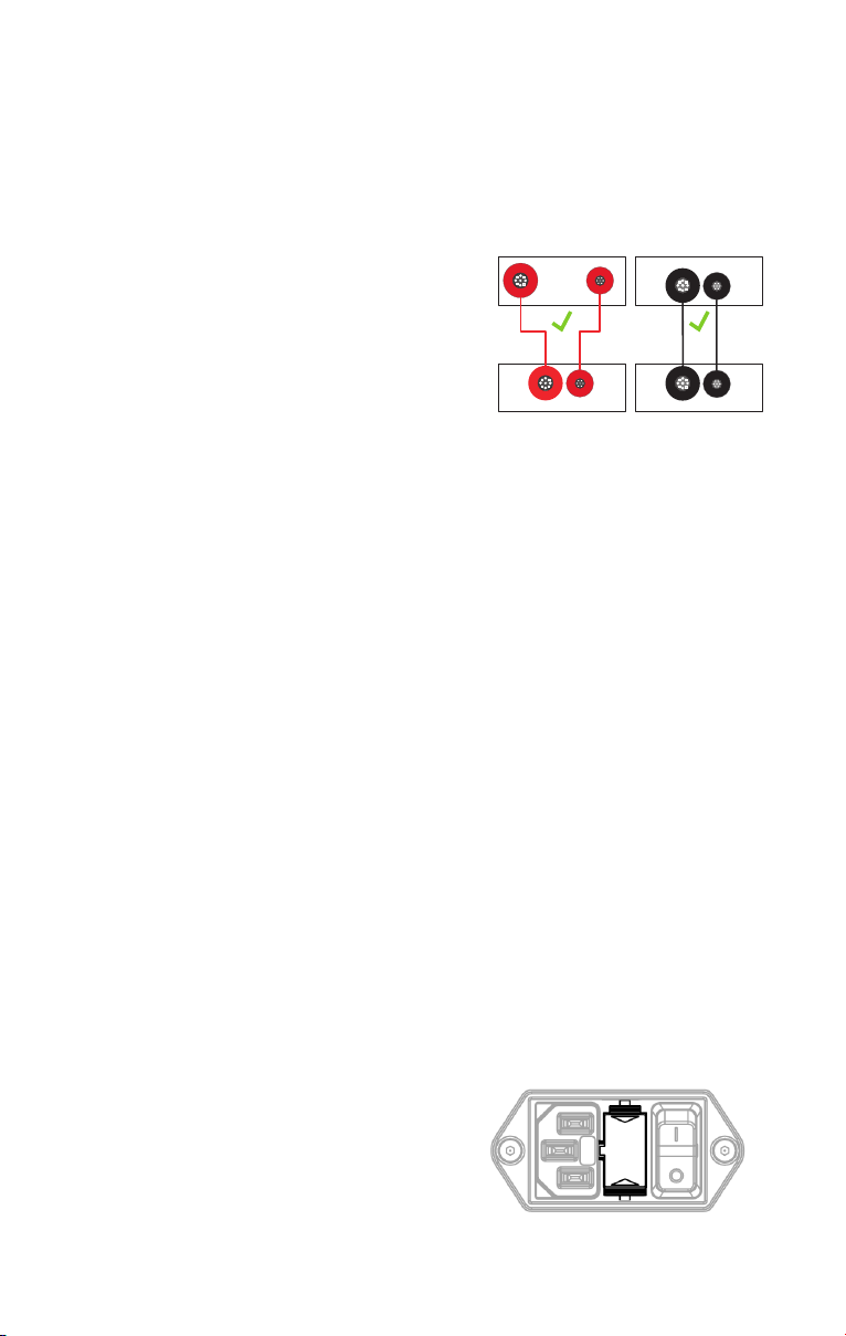
Note
There is a coloured ring around each LEMO
socket on both chassis and around each LEMO
plug on both cables. So if you possess several
Nagra HD devices such as an HD PREAMP and
an HD DAC X, be sure to connect the right power
supply chassis with the right audio device chassis
by using the correct cables (same colour of ring).
This is important because the power supply
chassis have different output configurations.
If you connect the wrong power supply chassis to one of your audio device chassis the
STATUS LED located on the rear panel of the power supply chassis above the SUB-D9
HOME AUTOMATION connector comes ON when you move the front rotary selector to a
position other than OFF. The audio device chassis does not switch ON for safety reasons.
ANALOG
HD DAC X
DIGITAL
HD PSU
HD PREAMP
ANALOG
HD PSU
DIGITAL
The fuse holder located in Mains appliance
inlet, between the IEC connector and the
switch, includes a replacement fuse.
The fuse type is: FST 5x20mm 250V.
Should you need to replace it, use only the same
T 3.15A L for 100V~ to 127V~ versions.
T 2A L for 230V~ to 240V~ versions.
fuse type and value.
↑
Page 14
Page 15
NAGRA HD PREAMP // INSTALLATION // 014 + 015
02
HD PREAMP description
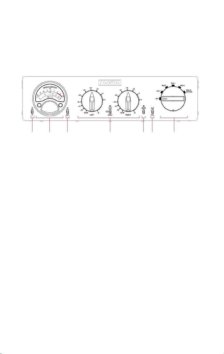
Front panel // audio device chassis
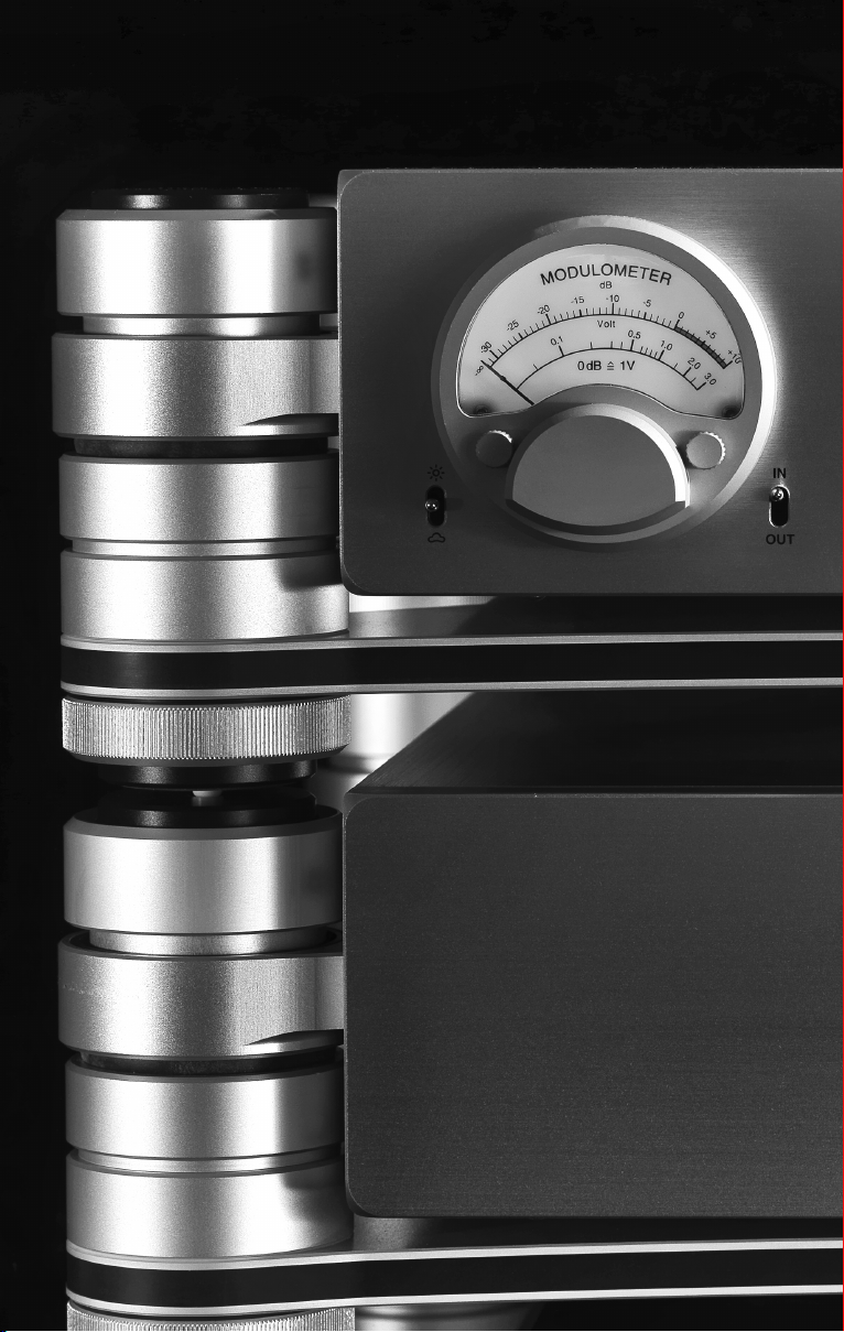
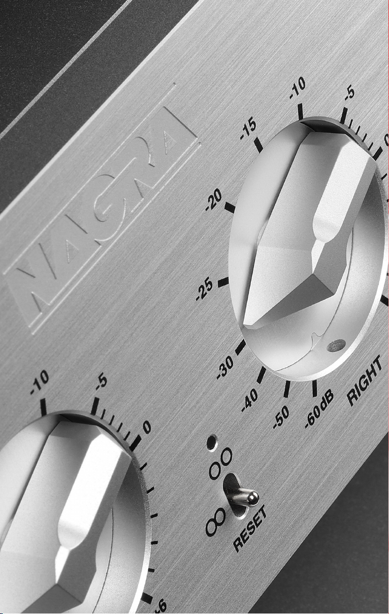
Modulometer & displays brightness switch.
Push up for more intensity, push down for less. There are 7 intensity levels.
Nagra Modulometer. Indicates level in dB. Reference 0 dB = 1 VRMS.
IN/OUT audio signal switch to select signal displayed on Modulometer.
Motorized volume level controls LEFT & RIGHT with synchronization switch
and warning LED for pre-heating & channels out of balance status.
MUTE switch with reminder LED.
RCA/XLR outputs selection switch.
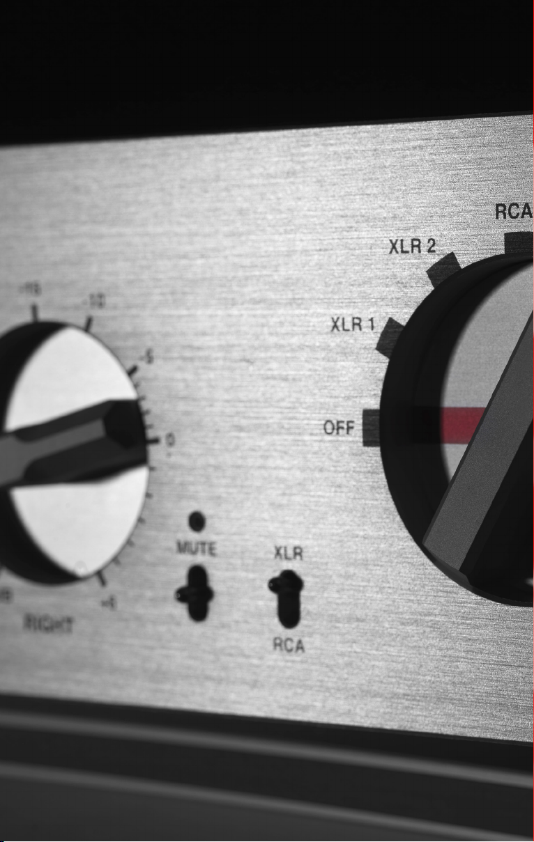
Front rotary selector.
When turned ON, the HD PREAMP will enter a 4 minute preheating phase in order to
optimize tubes and warm up critical components. This will allow your HD PREAMP to
offer excellent performance for a longer period of time.
Note: Should the HD PREAMP be switched OFF then ON again, the preheating phase
will start again from zero.
Page 16
Rear panel // audio device chassis
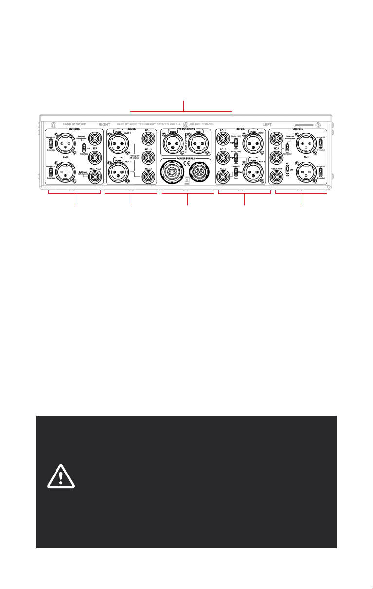
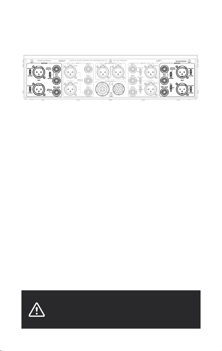
XLR and RCA outputs of right channel with connection type selectors.
XLR and RCA inputs of right channel.
BYPASS XLR inputs.
LEMO power supply inputs (Analog+Digital) with dedicated colour rings (black).
XLR and RCA inputs of left channel with sensitivity selectors for both channels.
XLR and RCA outputs of left channel with connection type selectors.
WARNING
Both XLR and RCA inputs are unbalanced. Balancing transformers for
XLR inputs are available as an option! XLR outputs are balanced. RCA
outputs are balanced or unbalanced (selection with switch). Please find
more details in the following paragraphs. Be careful, when cabling sources
and amplifiers to your HD PREAMP, to properly connect them with the
appropriate cables so as not to decrease audio signal quality! Pay attention
to the grounding to avoid any potential differences between equipment
that could permanently damage your HD PREAMP, especially when using
mains power filters!
Page 17
Audio inputs
NAGRA HD PREAMP // INSTALLATION // 016 + 017
02
RIGHT LEFT
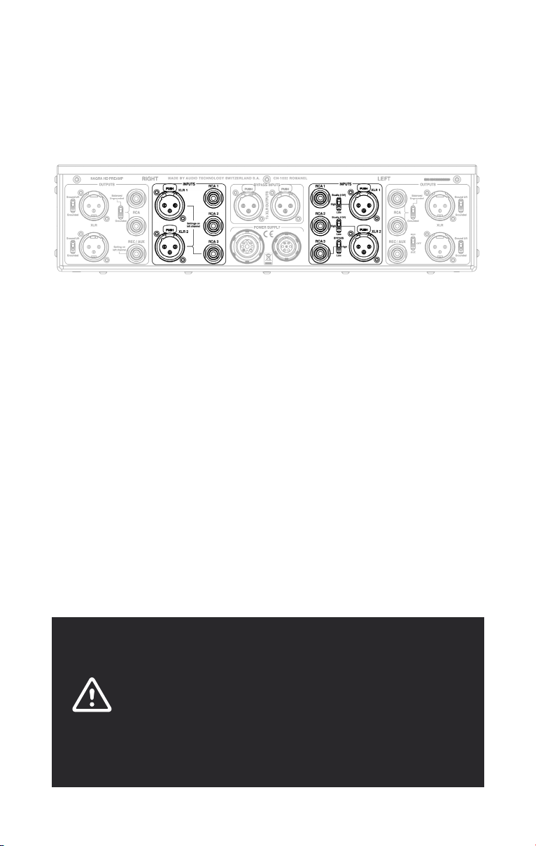
The input is selected with the front rotary selector
On both channels, sensitivity of RCA1 and RCA2 inputs is fixed (1V) whereas XLR1,
XLR2 and RCA3 inputs have adjustable sensitivity.
Three switches located next to the left channel inputs are dedicated to set sensitivity
of XLR1, XLR2 and RCA3 inputs on both channels simultaneously:
• XLR1, XLR2 = Studio (10V)/High (2V)/Low (1V, recommended position).
• RCA3 = BYPASS (RCA3 disabled)/High (2V)/Low (1V).
Note: When sensitivity is adjusted, you should switch the HD PREAMP off (front
rotary selector to OFF), and the HD PSU off (mains appliance inlet switch to 0), then
switch them on again in order for the adjustments to be memorized. XLR inputs are
unbalanced. Balancing transformers are available as an option. All our transformers
are designed and hand-wound on our premises in Romanel-sur-Lausanne, Switzerland.
If you require balanced inputs, please contact your Nagra dealer who will supply and
install the transformers. Please note that this option is only necessary when balanced
XLR inputs are required.
(see page 22).
WARNING
Please note that the HIGH sensitivity mode (2V) should only be used in
the case of connection to a source with a much higher audio signal level
than standard LOW sensitivity mode (1V). HD PREAMP inputs are very
tolerant of signal level and even with an audio signal level of 2V, you can
still use the LOW sensitivity mode (1V). When selecting HIGH sensitivity
mode (2V), an additional 6 dB voltage divider is connected to the audio
signal circuit that modifies the source impedance for the HD PREAMP
tube stage and consequently impacts the audio signal quality.
Page 18
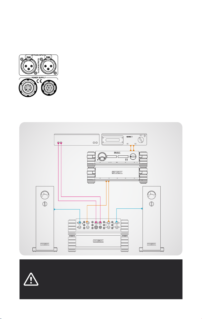
Bypass Inputs
CD
Both XLR Bypass input connectors are directly connected to
the XLR outputs when:
• The HD PREAMP is switched OFF.
• The RCA3 inputs are in Bypass mode and the front rotary
switch on the audio device chassis is set to RCA3/Bypass
position (see page 22).
This allows the connection of a second system, such as a
home cinema processor, to the amplifier connected to the HD
PREAMP. The pins of the XLR Bypass inputs and the XLR output
connectors are directly coupled for a true balanced signal path.
Here is an example of a configuration using the BYPASS direct path:
Home cinema processor NAGRA CD
NAGRA HD DAC X
NAGRA
HD AMP
NAGRA HD PREAMP
NAGRA
HD AMP
WARNING
Please note that when the HD PREAMP is in Bypass mode, the volume control
is bypassed too. The signal is directly routed to the XLR outputs. Be careful when
using a source with volume control. To avoid any damage to the speakers, adjust the
volume of the source to the minimum before setting the HD PREAMP in Bypass mode.
Page 19
NAGRA HD PREAMP // INSTALLATION // 018 + 019
02
Audio outputs
RIGHT LEFT
Depending on the position of the output selector switch on the audio device chassis front
panel (see pages 15 & 22), either XLR balanced outputs or RCA outputs will be activated.
The use of XLR balanced outputs is recommended because this creates a full galvanic
insulation that avoids possible ground loops when connected to mono power amplifiers.
XLR (balanced)
• GROUND LIFT means audio ground (pin 1 of XLR) is not routed to mains earth
(preamplifier chassis).
• GROUNDED means audio ground (pin 1 of XLR) is routed to mains earth
(preamplifier chassis).
RCA (balanced or unbalanced)
• SYMETRICAL UNGROUNDED means the cold point of the two upper RCA connectors
is not connected to the audio ground. They are in floating balanced configuration.
• GROUNDED means the cold point of the two upper RCA connectors is connected to
the audio ground. They are in standard unbalanced configuration.
REC / AUX (unbalanced)
• REC for recording purposes. Fixed output level whatever the volume control position.
• OFF means disabled REC/AUX output, no signal
(recommended position if this output is not used).
• AUX means auxiliary output with a variable output level according to the volume
control position.
WARNING
Please be sure not to have any potential difference between HD PREAMP
and other equipment (correct grounding). Otherwise there is a risk of HD
PREAMP damage when adjusting volume level.
Page 20
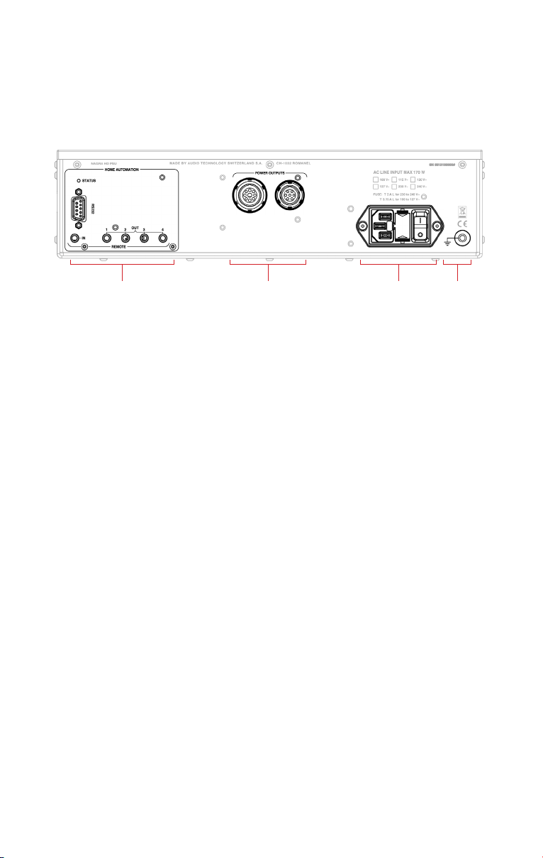
Rear panel // power supply chassis
STATUS LED for software upgrade & detection of wrong audio device chassis
SUB-D9 for Home automation
REMOTE IN (1x) to be driven by “master” device
REMOTE OUT (4x) to drive “slave” devices
LEMO power supply outputs (Analog 9p, Digital 7p)
Mains appliance inlet with switch and fuse
+ voltage version & fuse value information
Ground post
About ground post
This feature is seldom used but can sometimes come in handy to solve specific setup
issues. Your NAGRA dealer will assist you on when and how to use this connector.
Page 21
NAGRA HD PREAMP // INSTALLATION // 020 + 021
02
Page 22
03
HD PREAMP
Only proceed if you have completed the installation steps as described in the previous chapter
INSTALLATION OF YOUR HD PREAMP.
Power on & Audio input selection
To use your HD PREAMP, firstly you must push the Mains power switch to position 1
(ON). The Mains power switch is located on the rear panel of power supply chassis.
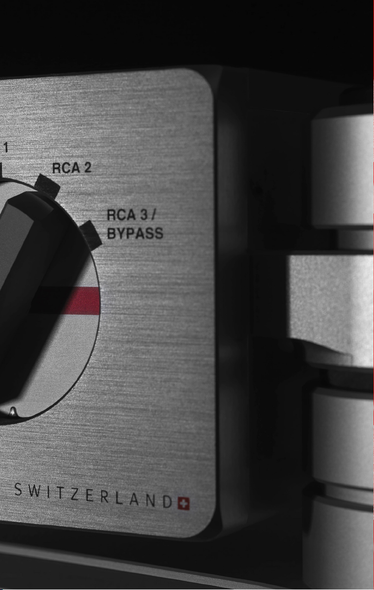
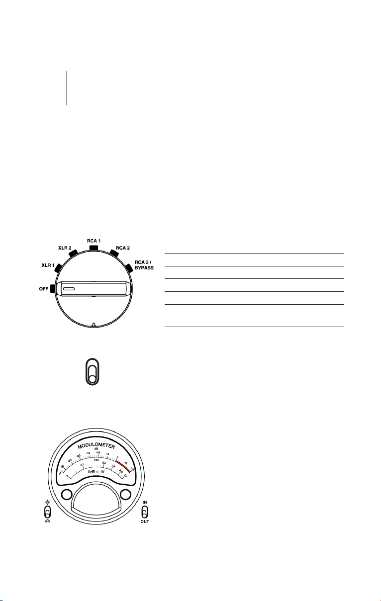
The front rotary selector offers 6 positions to select the desired input or to switch
your HD PREAMP OFF:
OPERATION OF YOUR HD PREAMP //
OFF Similar to STANDBY, the unit is
still powered but the consumption
remains very low
XLR1 Selection of XLR1 input
XLR2 Selection of XLR2 input
RCA1 Selection of RCA1 input
RCA2 Selection of RCA2 input
RCA3/BYPASS Selection of
RCA3/BYPASS input
XLR
RCA
Audio output selection
Connectthe HDPREAMPoutputto youramplifier(s)
by using either the XLR or RCA connectors according to the XLR/RCA switch position on the audio
device chassis front panel.
Nagra modulometer
The Nagra modulometer is inherited from the second
recorder developed by Nagra back in 1952, the Nagra
II. The Modulometer is a typical Nagra precision
instrument that displays the necessary information to
achieve the best possible audio level setting. In the
case of the HD PREAMP, the modulometer displays
either the selected audio input level or the selected
audio output level.
Reference 0 dB = 1 VRMS .
Left channel – black needle
Right channel – red needle
Page 23
NAGRA HD PREAMP // OPRERATION // 022 + 023
03
Light intensity adjustment
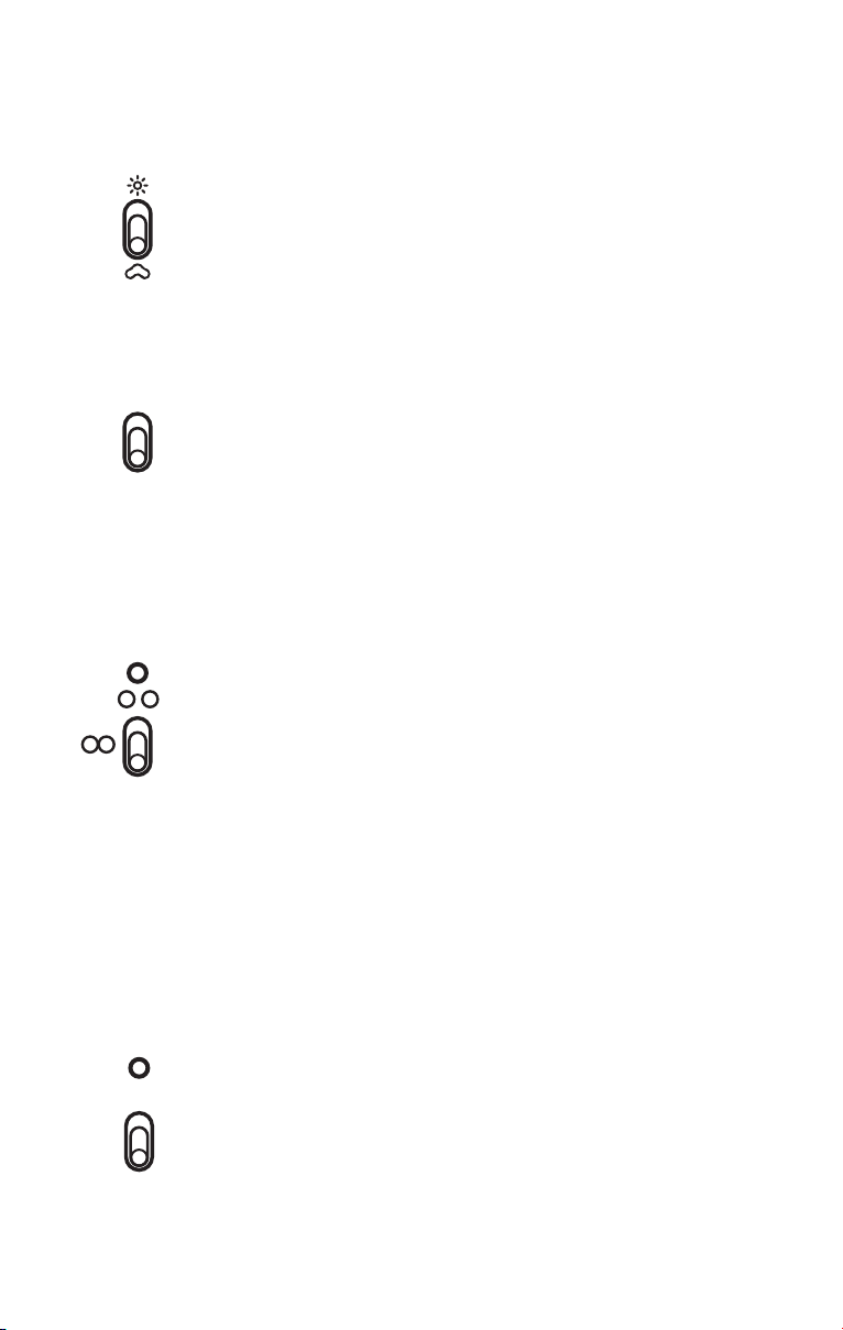
This two-way toggle switch allows you to adjust the Modulometer &
displays backlight intensities. Pushing the toggle up will increase the
brightness, pushing it down will lower the brightness all the way to
complete extinction. There are 7 different intensity levels.
IN
OUT
Modulometer IN/OUT
Selection of audio signal displayed by modulometer.
Volume control synchronization & warning LED
Warning LED
Blinking during preheating process.
ON when preheating is ended and volume controls are desynchronized.
OFF when preheating is ended and volume controls are synchronized.
RESET
○ ○ Desynchronization of both volume controls.
They can be moved separately.
○ ○ Synchronization of both volume controls. They move simultaneously.
RESET
When pushing switch on RESET, both volume controls calculate an
average between their positions and move to this average position
(useful for resynchronizing volume controls).
MUTE
Mute
The outputs of the HD PREAMP can be set to standby mode when
you activate the MUTE switch. Pulling up the switch will activate the
muting (no more sound) and light the yellow LED. Pulling down the
switch will deactivate the muting and turn the yellow LED off. The HD
PREAMP outputs will be working again.
Page 24
IR Remote Control Unit
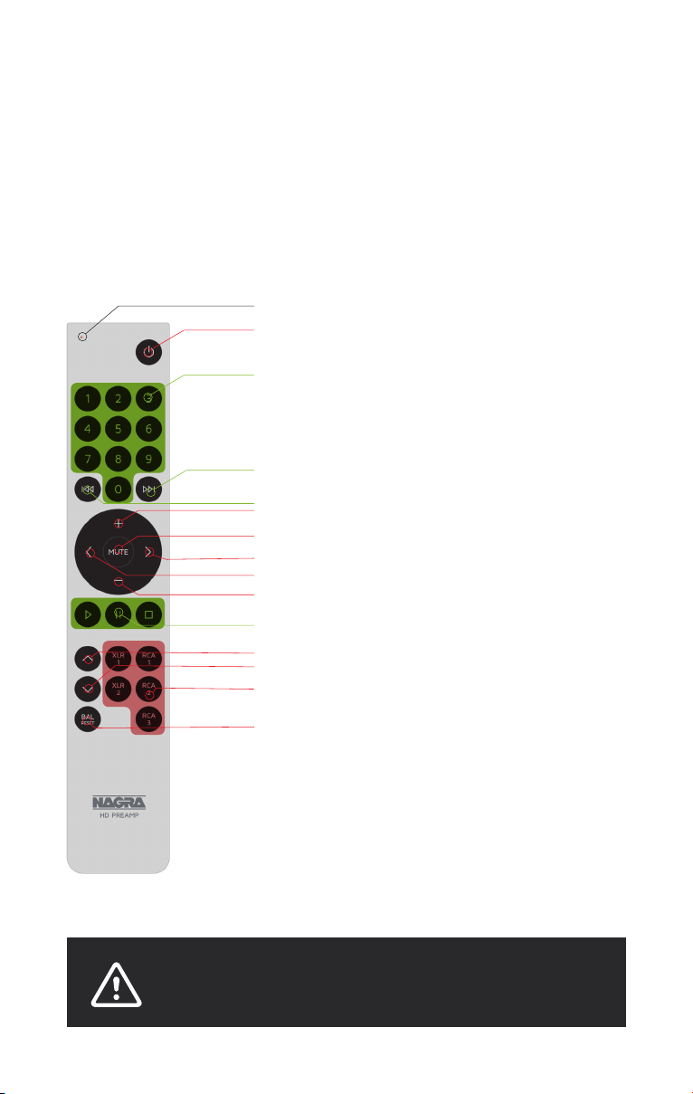
The HD PREAMP currently comes with the new IR Remote Control Unit with Philips RC-5
format encoding. You may also use a Nagra RCU or RCU-II IR Remote Control Unit.
As they require a different communication protocol (RECS-80), please contact your Nagra
dealer to make the necessary adjustments inside your HD PREAMP.
Red LED
Power OFF - ON // HD PREAMP
Numeric keyboard //CD track
Short press: next track (CD) or Long press: fast forward (CD)
Short press: track restart (CD) or Long press: fast backward (CD)
Volume up // HD PREAMP
Mute // HD PREAMP
Right balance on right volume control // HD PREAMP
Left balance on right volume control // HD PREAMP
Volume down // HD PREAMP
Standard commands from left to right: PLAY, PAUSE, STOP (CD)
Next input selection // HD PREAMP
Previous input selection // HD PREAMP
Direct input selection // HD PREAMP
Balance reset // HD PREAMP
HD PREAMP
CD
Note
To protect the Li battery in the device during transport,
the Remote Control Unit keys have been locked. To unlock
them, press on MUTE for 5 seconds until the red LED
blinks twice.
WARNING
The Remote Control Unit, with battery installed, must not be exposed to
excessive heat such as sunshine, fire or similar.
Page 25

NAGRA HD PREAMP // OPRERATION // 024 + 025
03
Red LED on Remote Control Unit
The red LED lights ON when pressing any key on the Remote Control Unit. If not, it
means either the Remote Control Unit keyboard is locked or the Remote Control Unit Li
battery is empty. Insert the unit into the docking station to charge the Li battery.
Power OFF / ON key
Toggle key to switch the HD PREAMP ON and OFF. When switching ON, HD PREAMP
automatically turns the front selector to the last input selection active before last power OFF.
Note: This key is not operative when a REMOTE AUTOMATION jack cable is connected to the
REMOTE IN socket of the power supply chassis!
–
+
and
To move both left and right volume controls simultaneously, either up or down, press on
key briefly for a ±0.5dB change, or longer for bigger volume differences. The volume
controls can be set to work either in synchronized mode or in desynchronised mode.
and keys
With synchronized volume controls = No effect.
With desynchronized volume controls = step of ±0.5dB, only on right volume control.
BAL
RESET
With synchronized volume controls = No effect.
With desynchronized volume controls = both volume controls calculate an average
between their positions and move to this average position (useful for resynchronizing
volume controls).
volume keys
BAL RESET key
Page 26
Docking station usage
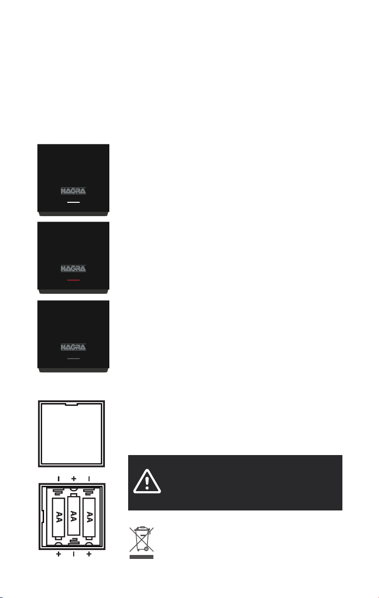
To charge the Remote Control Unit Li battery, insert the unit into the docking station
(unit keyboard towards docking station front). Fully charged, the Remote Control Unit
will work for around 2-3 months, depending on usage. The 3x AA-dry cells in the
docking station will be able to charge the Li battery for about 3 years.
Docking station LED indicator
The LED on the front indicates the condition of the Remote
Control Unit Li battery when the unit is inserted into the
docking station:
WHITE blinking = The Li Battery in Remote Control Unit is
charging.
RED blinking = The Remote Control Unit is defective. Please
contact your Nagra dealer.
Permanently OFF = The Li Battery in the Remote Control Unit is
fully charged or the Remote Control Unit is not properly inserted
into the docking station. Remove and reinsert the unit into the
docking station. If the LED blinks white everything is OK, if not,
the 3x AA-dry cells are exhausted and must be exchanged.
Note
When the Li Battery in the Remote Control Unit is fully charged, the
docking station only uses a small amount of current to maintain
the full charge. There is no risk of overload even if the Remote
Control Unit is inserted in the docking station for a long time!
Battery installation/exchange in docking station
Open the battery box by removing the bottom panel of the
docking station (magnet lock). Insert your thumb nail into the
groove and lift the panel up. Replace empty batteries with 3x
new AA-dry cell batteries.
WARNING
Do not use any mechanical tool to open the docking
station battery box; you could damage the body or the
panel of the unit!
By ensuring battery is disposed of correctly, you will help prevent
potential negative consequences for the environment and human
health. The recycling of materials will help to conserve natural
resources. For more detailed information about recycling of battery,
please contact your local authority, your household waste disposal
service or the shop where you purchased the battery.
Page 27

NAGRA HD PREAMP // OPRERATION // 026 + 027
03
Use of a universal IR Remote Control Unit
The HD PREAMP responds to IR (Infra Red) signals encoded in Philips RC-5 format.
A default code 16 has been allocated to the HD PREAMP as a preamplifier. Should you
wish to program your universal remote control, please use the following table:
Code Device
group
number
HD PREAMP
1 16 XLR1
2 16 XLR2
3 16 RCA1
4 16 RCA2
5 16 RCA3
12 16 Power ON/OFF
13 16 Mute
16 16
17 16
20 16
26 16
27 16
32 16
33 16
CD
0 20 0
1 20 1
2 20 2
3 20 3
4 20 4
5 20 5
6 20 6
7 20 7
8 20 8
9 20 9
32 20
33 20
48 20
50 20
52 20
53 20
54 20
Key
Page 28
Remote automation
TIP
RING
SLEEVE
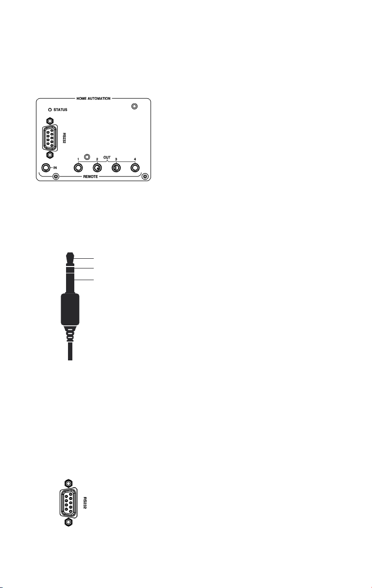
The power supply chassis has 1x 3.5mm (1/8”)
stereo jack socket REMOTE IN (to connect a
master device) and 4x 3.5mm (1/8”) stereo jack
socket REMOTE OUT (to connect slave devices).
It allows you to switch a complete configuration of
Nagra devices ON/OFF by only driving the master
device manually or with an IR Remote Control Unit.
If a 3.5mm (⅛”) stereo jack connector is inserted
into the “Remote IN” input at the back of the power
supply chassis, this control gains priority over the
IR Remote Control Unit and RS232 commands
(ON-OFF key switch on IR Remote Control Unit no
longer works).
Short between TIP and RING: HD PREAMP is
switched ON. As soon as the HD PREAMP is
switched ON, the front rotary switch turns itself to
the selected input before it was last switched off.
If you manually turn the front rotary switch to the
OFF position when TIP and RING are shorted, it
will turn itself back to the last selected input. Use
standard straight cable to connect the different
devices (except for the REM (REMOTE IN) input of
a slave Nagra MPS). For more information, please
ask your Nagra dealer who will provide you with
a specific Nagra document on the topic: Nagra
Remote automation - User + service instruction How does it work?
Home automation
All commands are sent/received on the SUB-D9
connector located on the rear panel of the power
supply chassis. The serial settings are: 115200
bits per second, 8 data bits, no parity, 1 stop bit.
All commands are executed after sending the
command itself and terminating with a <CR>
(carriage return).
Page 29

NAGRA HD PREAMP // OPRERATION // 028 + 029
03
Command Description
BALLEFT Step balance left
BALRESET Reset balance
BALRIGHT Step balance right
BLUP Increase backlight intensity
BLDOWN Decrease backlight intensity
MUOFF Mute OFF
MUON Mute ON
MVDOWN Decrease volume
MVUP Increase volume
PWON Power on the device
PWSTANDBY Set device to standby (or power off)
SILEFT Previous input
SIRIGHT Next input
SI1 Select input 1
SI2 Select input 2
SI3 Select input 3
SI4 Select input 4
SI5 Select input 5
Tube ageing
Nagra selects the HD PREAMP tubes according to exacting criteria. Their theoretical
minimum useful life is 5’000 hours. In actual fact, some tubes operate consistently for
more than 10’000 hours.
Thus, the useful life of the tubes is somewhat unpredictable. Rather than replacing the
tubes arbitrarily after 5’000 hours, we suggest that you identify the signs of ageing:
→ Distortion gently increases to an audible level
→ Presence of clicks (dry, brief noises, like dead wood snapping)
→ Presence of pops, brief noises in the low frequencies
→ Presence of hiss, higher background noise
→ Reduction of spaciousness, loss of naturalness
As soon as one of these signs appears, please contact your Nagra dealer to order an
HD PREAMP replacement tube kit.
HD PREAMP software update
The update is carried out with two MicroSD memory cards, one for the audio device
and one for the power supply. You will be advised of the availability of any updates by
your dealer who will install them.
Case cleaning
Clean the HD DAC X casing by using a soft, non-fluffy, slightly damp cloth. Do not use
any cleaning products that could have a corrosive effect.
Disposal of old electrical & electronic equipment (Applicable in the European Union and other
European countries with separate collection systems). This symbol on the product or on its packaging
indicates that it should be handed over to the applicable collection point for the recycling of electrical
and electronic equipment. By ensuring this product is disposed of correctly, you will help prevent
potential negative consequences for the environment and human health. The recycling of materials
will help to conserve natural resources. For more detailed information about recycling of this product,
please contact your local authority, your household waste disposal service or the shop where you
purchased the product.
Applicable to the following devices: HD PREAMP and all the package contents
Page 30

04
HD PREAMP
TECHNICAL SPECIFICATIONS //
Input impedance
Output impedance
Frequency response
Dynamic range
Input level to reach 0 dB on modulometer
Sensitivity LOW
Sensitivity HIGH
Sensitivity STUDIO
Harmonic levels
h2
h3
h5 & h7
Crosstalk
Remote automation
Input
Output
Home automation
Mains power
Power consumption
Mains fuse
230V~ to 240V~
100V~ to 127V~
Operating temperature
Operating environment Indoor only IP30
Dimensions LxWxH with VFP
Power supply chassis (HD PSU)
Audio device chassis
Weight with VFP
Power supply chassis (HD PSU)
Audio device chassis
Specifications may change without notice
> 50 k
< 0.2
< 40
10 Hz - 100 kHz
10 Hz - 200 kHz
> 150 dB Volume @ -15 dB
1 V RMS
2 V RMS
10 V RMS
< -70 dB
< -120 dB
< -150 dB
> 130 dB
> 110 dB
1x 3.5mm (⁄”) stereo jack socket
4x 3.5mm (⁄”) stereo jack socket
1x SUB-D9 connector RS232
100V~, 115V~, 120V~,
127V~, 230V~ or 240V~
NOT ADJUSTABLE
170W max
T 2A L
T 3.15A L
+15°C to +35°C
+59°F to +95°F
433x436x121 mm
433x436x121 mm
16.5 kg
13.5 kg
Volume @ -15 dB
Volume @ 0 dB
+0.1 dB / -0.1 dB
+1.5 dB / -0.2 dB
Volume @ 0 dB
@ 1 kHz, 1 V out, no load
@ 1 kHz, 1 V RMS
@ 20 kHz, 1 V RMS
Input command
Output switching by relay
115200 bits/s, 8 data bits,
no parity, 1 stop bit
±10%, 50-60 Hz
FST 5x20mm 250V
FST 5x20mm 250V
Moderate climate
17.05x17.17x4.76 in
17.05x17.17x4.76 in
36.38 lb
29.77 lb
Page 31

MADE IN SWITZERLAND
MANUFACTURER AUDIO TECHNOLOGY SWITZERLAND
© NAGRA // EDITION 2019
Page 32
nagraaudio.com
 Loading...