

Nady Systems MGT-16, MHT-16, WHM-16, LINK-16 Owner's Manual
Instructions for use with any of these transmitters
MGT-16 SYSTEM
WHM-16 SYSTEM
LINK-16 SYSTEM
MHT-16 SYSTEM
MT-16A
MT-16R
MH-16
LK-16
WH-16

Contents
Introduction ............................................................................. 2
Using this Manual ..................................................................... 2
System Features (MGT-16/MHT-16/LINK-16/WHM-16) ................... 3
Quick User Controls/Connections Guide ....................................... 4
MGT-16 Wireless Instrument Receiver ..................................... 4
MT-16A/R Instrument Transmitter ........................................... 6
MH-16 Horn Instrument Transmitter ........................................7
LK-16 Snap-On Transmitter ....................................................8
WH-16 Head-Worn Transmitter ............................................... 9
System Operation .....................................................................10
MGT-16 Wireless Receiver ...................................................... 10
MT-16A/R, MH-16, LK-16, WH-16 Transmitters ......................... 11
Miscellaneous Tips .................................................................... 14
Cautions and Troubleshooting .................................................... 15
MGT-16 System DIP-Switch Frequency Selection Chart .................. 16
Specications ........................................................................... 17
Servicing ................................................................................. 18
Warranty ................................................................................. 19
Introduction
Thank you for choosing the Nady MGT-16/MHT-16/LINK-16/WHM-16
Mini Wireless System. Each of these units is a 16-channel, ultra-compact
UHF wireless system featuring 16 selectable frequencies, up to 250
feet operating range, and infrared ASC
TM
(Auto Sync Channel) for quick
convenient setup. The “pedal-style” receiver can be placed anywhere.
Using This Manual
This booklet provides information regarding the use of the MGT-16, MHT16, LINK-16 or WHM-16 Wireless System with the MGT-16 receiver and
one of the following transmitters: MT-16A/R, MH-16, LK-16 or WH-16. It
includes a description of features and a step-by-step guide to operation
of the particular system you have purchased. This manual should answer
any questions you may have about the operation and servicing of your
system.
2

MGT-16 Systems
• 16 user-selectable UHF PLL frequencies for interference-free operation
• Up to 250’ operating range, line-of-sight
• ASC
TM
(Auto Sync Channel) infrared wireless download pairs
transmitters to selected receiver frequency for quick, easy setup
MGT-16 Instrument Receiver
• Compact, portable, “pedal style” receiver can be placed anywhere
• Dual ¼ wave antennas
• Unbalanced ¼” line output plug
• Power On/Off/Mute switch; Volume Control; LED indicators for Low Battery, and RF
Reception; DIP-switch channel selection with IR sync to transmitter; IR Sync LED
• Powered by DC adapter (included) or two AA alkaline batteries for
portability (Up to 8 hours battery life)
Available Transmitters
MT-16A & MT-16R Instrument Transmitters
• Choice of two transmitter housings— MT-16A with 30° angled ¼” plug for use with
either recessed or surface mounted jacks, or MT-16R with 90° angled ¼” plug for
surface mounted jacks only
• Up to eight hours of battery life from a single AAA alkaline or NiMH rechargeable
battery
• Infrared channel sync with receiver for instant setup
• Power On/Off switch; Power/Low Battery LED indicators; IR Sync LED
• Input level attenuation switch; internal audio level control trim-pot
• External exible wire antenna
MH-16 Saxophone (Horn) Instrument Transmitter
• Clip-on-the-horn barrel style without any tangling wires
• Up to eight hours of battery life from a single AAA alkaline or NiMH rechargeable battery
• Infrared channel sync with receiver for instant setup
• Power On/Off switch; Power/Low Battery LED indicators; IR Sync LED
• Input level attenuation switch; internal audio level control trim-pot
• External exible wire antenna
LK-16 Snap-On Transmitter
• Female XLR input connector for mounting transmitter on any hardwired dynamic microphone
• Up to eight hours of battery life from a single AAA alkaline or NiMH rechargeable battery
• Infrared channel sync with receiver for instant setup
• Power On/Off switch; Power/Low Battery LED indicators; IR Sync LED
• External exible wire antenna
WH-16 Head-Worn Transmitter
• Head-Worn (over ears style) transmitter for hands free, cordless operation
• Up to eight hours of battery life from a single AAA alkaline or NiMH rechargeable battery
• Infrared channel sync with receiver for instant setup
• Power On/Off switch; Power/Low Battery LED indicators; IR Sync LED
• External exible wire antenna
System Features
3
4
Quick User Controls/Connections Guide
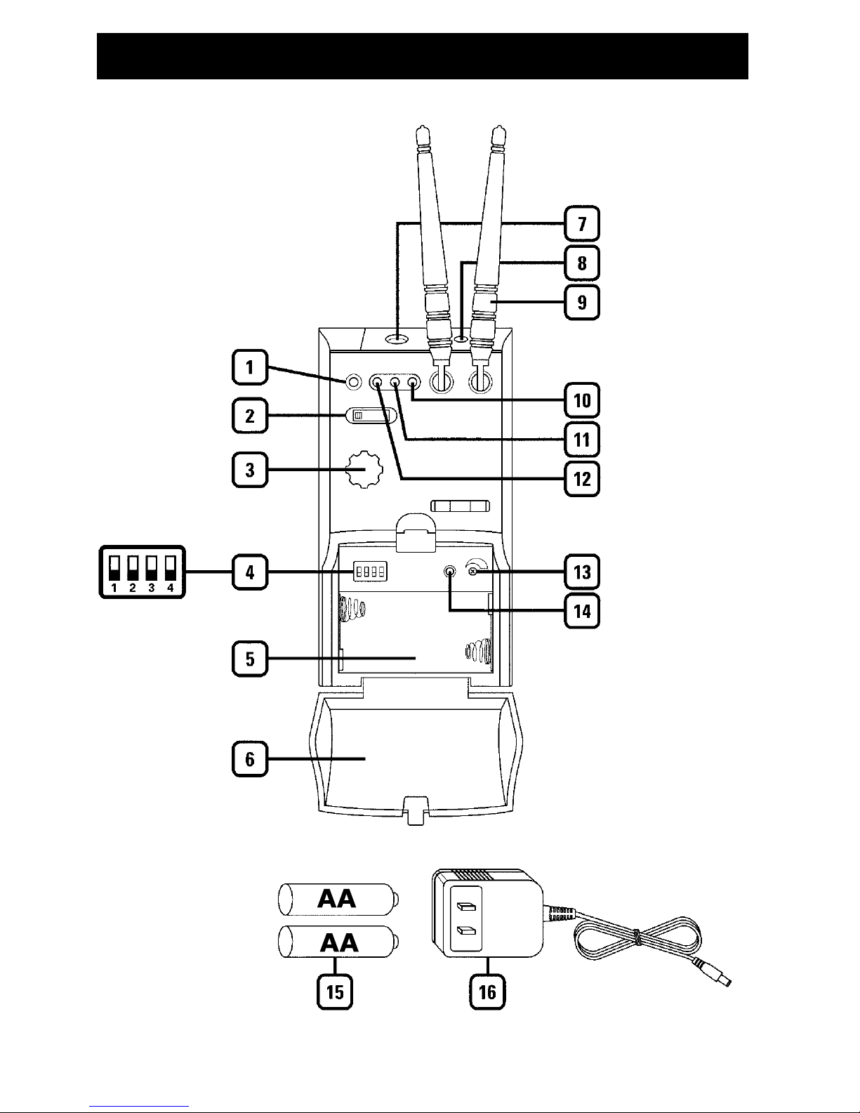
MGT-16 Receiver

1. ASC™ IR SYNC INFRARED LED WINDOW For downloading selected Channel
(Frequency) to transmitter
2. POWER SWITCH Select OFF/MUTE/ON (MUTE=power On, audio output highly
attenuated)
3. VOLUME CONTROL Adjusts the audio output level—at maximum setting the gain
will be about +4dB over a direct instrument-to-cord-to-amp connection
4. CHANNEL SELECT DIP-SWITCH Select one of 16 pre-set channels per MGT-16
DIP-Switch Frequency Selection Chart (see page 20)
5. BATTERY COMPARTMENT Insert two AA batteries for optional DC operation, note
correct polarity
6. BATTERY COMPARTMENT COVER Push tab to release hinged door
7. AUDIO OUTPUT JACK For connecting audio cable
8. DC INPUT JACK For connecting external AC/DC adapter for powering receiver
9. ANTENNAS Dual ¼ wave for best reception
10. SIGNAL LED (Green) Indicates the received signal from the transmitter
11. LOW BATTERY LED (Amber) Lights continuously to indicate batteries need
replacement (if not using power adapter)
12. POWER ON LED (Red) will light indicating the receiver is operational
13. MUTE (SQUELCH) CONTROL Adjust with a small screwdriver inserted in slot.
Controls the mute level for the receiver—turn counter-clockwise for maximum range;
turn clockwise, if needed, to minimize noises from outside RF interference upon
muting.
Note: Set control carefully. If trim-pot is turned past minimum and maximum
adjustment points it may need to be backed up to achieve desired setting.
14. ASC™ IR SYNC BUTTON Press to make the IR link download the receiver’s
selected frequency to the TX. First, turn on the system transmitter supplied (or turn
off and then on again if already on) and position its IR window 6-12” away from the
MGT-16’s IR WINDOW (1), press the SYNC button once and wait one second for the
transmitter to respond. If the IR data download is successful, the receiver
SIGNAL LED (10) will light, indicating the transmitter is locked in and transmitting.
15. AA BATTERIES Two required for optional battery operation, alkaline or NiMH
16. POWER ADAPTER For AC operation (included)
Quick User Controls/Connections Guide
MGT-16 Receiver
5
Quick MGT-16 User Controls/Connections Guide
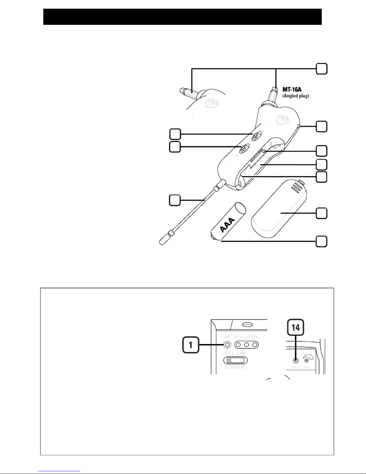
MT-16A/R Instrument Transmitter
ASC
TM
IR Sync Download of Selected
Frequency of MGT-16 Receiver to
MT-16A/R, MH-16, LK-16 or WH-16
Transmitter
(1) ASC™ IR SYNC INFRARED LED WINDOW
For downloading selected Channel
(Frequency) to transmitter
(21, 31, 46, 56) MT-16A/R, MH-16, LK-16, WH-16
TRANSMITTER IR RECEPTOR SENSOR/WINDOW
Infrared LED sensor for linking the TX to the RX
during IR frequency download.
(14) ASC
™
IR SYNC BUTTON Press to make the IR link
download the receiver’s selected frequency to the TX.
First, turn on the system transmitter supplied (or turn
off and then on again if already on) and position its
IR window 6-12” away from the RX IR window, press
the SYNC button once and wait one second for the RX
to respond. If the IR data download is successful, the
receiver SIGNAL LED (10) will light indicating the
transmitter is locked in and transmitting.
17
18
19
20
21
22
23
26
25
24
17. POWER SWITCH Slide in arrow direction
to power transmitter On
18. 15dB ATTENUATION PAD Select to
reduce the input gain by 15dB for higher level
audio input signals
19. INPUT ¼” PLUG Connect directly
intoguitar/bass output jack
20. POWER & LOW BATTERY LED Flashes
once at power up, continous ashing indicates
battery needs replacement
21. IR RECEPTOR SENSOR/WINDOW
Infrared LED sensor for linking the TX to the RX
during IR frequency download
22. BATTERY COMPARTMENT Insert one AAA
battery, observing correct polarity
23. INTERNAL AUDIO LEVEL ADJUST
Remove battery to access slot and adjust
internal trim-pot with small screwdriver for
optimal input level setting. Note: this is to be
done only in rare cases as factory level setting
is already optimized for most guitars and basses
and 15dB Pad also available.Note: Set control
carefully. If trim-pot is turned past minimum
and maximum adjustment points it may need to
be backed up to achieve desired setting.
24. ANTENNA Permanently attached exible
antenna
25. BATTERY Single AAA alkaline or NiMH
battery required for operation
26. BATTERY COMPARTMENT COVER Slide
to open
6
 Loading...